Abstract
Multimodal image fusion is an efficient information integration technique, with infrared and visible light image fusion playing a critical role in tasks such as object detection and recognition. However, obtaining images from different modalities with high-precision registration presents challenges, such as high equipment performance requirements and difficulties in spatiotemporal synchronization. This paper proposes an image augmentation and registration method based on an improved NeRF (neural radiance field), capable of generating multimodal augmented images with spatially precise registration for both infrared and visible light scenes, effectively addressing the issue of obtaining high-precision registered multimodal images. Additionally, three image fusion methods—MS-SRIF, PCA-MSIF, and CNN-LPIF—are used to fuse the augmented infrared and visible images. The effects and applicable scenarios of different fusion algorithms are analyzed through multiple indicators, with CNN-LPIF demonstrating superior performance in the fusion of visible and infrared images.
1. Introduction
Image fusion is an effective method for information integration, and the fusion of infrared and visible images is one of the most important and efficient approaches. Infrared data reflects the thermal radiation characteristics of objects, particularly under complex conditions such as smoke, fog, or low illumination, but infrared images lack texture details. Visible light images contain abundant texture and background information, and fusing them with infrared images can yield a more comprehensive composite image. However, during the fusion process, infrared and visible images usually come from different types of sensors with varying viewpoints and fields of view, which may result in geometric distortion and spatial misalignment. The differences between sensors lie not only in their imaging principles (infrared based on thermal radiation, visible based on reflected light), but also in their resolution, dynamic range, and spectral response. Additionally, although infrared–visible image fusion has important applications across various fields, devices capable of simultaneously capturing both modalities are relatively scarce. In summary, acquiring high-quality, directionally consistent infrared and visible data in the same scene is challenging, and sensor registration and imaging mismatch further complicate bimodal image fusion. Designing and implementing efficient and accurate bimodal image fusion strategies, while addressing sensor registration and synchronization challenges, has become a critical issue in image fusion research [,,].
To address the alignment problem in multimodal fused images, Ma et al. proposed a unified model based on Gaussian field criteria that simultaneously adapts to infrared and visible image features []. Seong G. Kong et al. adopted a multiscale processing approach to enhance the accuracy and robustness of face recognition []. Jingyuan Gao et al. achieved geometric alignment of different modalities by incorporating sparse 3D reconstruction []. Chen et al. innovatively used color images as guidance and employed convolutional neural networks (CNNs) to achieve high-quality thermal image super-resolution []. Bruce D. Lucas et al. adjusted spatial transformation relationships between images to achieve precise spatial alignment of multimodal data []. Ma, JY et al. proposed a feature-guided Gaussian mixture model (GMM) approach, delivering more reliable image alignment for clinical applications such as disease monitoring and treatment planning []. David A. Clausi et al. introduced algorithm variants into the automatic registration of remote sensing images (ARRSI) to enhance model accuracy and address remote sensing image registration issues [].
Since its initial proposal [], the neural radiance field (NeRF) has become a core method for novel view synthesis, though it suffers from slow training and poor robustness. Plenoxels accelerated the training process using sparse voxels []. NeRF++ and Mega-NeRF extended NeRF applications to complex scenes and large-scale environments [,]. Semantic-NeRF integrates semantic information by mapping spatial coordinates to semantic labels, aiding object recognition []. PixelNeRF learns scene priors to enable novel view synthesis from sparse image sets []. VT-NeRF combines vertex and texture latent codes to improve the modeling accuracy of dynamic human scenes, while CLIP-NeRF introduces multimodal control for 3D object editing into NeRF using text and image prompts [,]. UAV-ENeRF achieves large-scale UAV scene editing []. SeaThru-NeRF incorporates a SeaThru-based scattering medium rendering model into the NeRF framework, combined with an adapted network architecture to jointly learn scene information and medium parameters, thereby enabling realistic novel view synthesis and medium removal in underwater and foggy environments []. Jonathan T. Barron et al. replaced ray sampling with cone tracing, improving anti-aliasing, training efficiency, and reducing texture flickering []. Alex Yu et al. converted NeRF’s volumetric rendering into a sparse octree structure to enable real-time and high-frame-rate rendering without sacrificing quality []. Thomas Müller applied multiresolution hash encoding to accelerate NeRF training significantly []. Various NeRF variants have improved model performance in terms of reconstruction accuracy, training speed, robustness, and application scenarios.
Early image fusion methods mainly relied on multiscale transforms such as wavelets or Nonsubsampled Contourlet Transform (NSCT), lacking semantic understanding [,]. Later, convolutional sparse representation (CSR) methods were used for feature transformation, addressing dependency in image decomposition []. With the advancement of deep learning, CNNs and Generative Adversarial Networks (GANs) emerged, improving image fusion speed and quality [,]. A residual Swin Transformer fusion network based on saliency detection was proposed, which effectively highlights thermal targets in infrared images while preserving texture details []. As image fusion algorithms diversify, more quality evaluation metrics are needed. Zhang et al. [] proposed VIFB, a benchmark dataset for visible and infrared image fusion, providing a unified platform for evaluating fusion algorithms. Haghighat et al. [] designed a no-reference image fusion quality metric based on the mutual information of image features, addressing the limitations of traditional metrics in reflecting subjective quality. Wang et al. [] introduced a reference-based image super-resolution method that matches high- to low-level features and fuses complementary information from reference images to improve reconstruction quality. Similarly, Kumar and Bawa [] developed a no-reference image quality assessment metric based on regional mutual information, enabling more fine-grained quality evaluation. You et al. [] proposed a novel fusion quality metric that combines mutual information and structural similarity, balancing statistical features and structural consistency to enhance the comprehensiveness and practicality of image quality evaluation.
Among them, some algorithms performed well; Liu Yu et al. proposed a CNN-based fusion method for infrared and visible images, achieving state-of-the-art image quality and fast computation [,]. Liu combined multiscale transform (MST) and sparse representation (SR) to improve the quality and robustness of multimodal image fusion []. Yonghua Li et al. proposed a fusion method based on saliency detection and LatLRR-FPDE, which enhanced infrared target saliency and texture detail expression, achieving superior visual quality and information preservation in multiscale fusion [].
Existing studies on visible and infrared image registration suffer from low accuracy due to geometric differences and modality-specific features, making it difficult to align images captured with different camera poses and intrinsic parameters. In terms of image fusion methods, the lack of semantic understanding limits the ability to integrate complementary information from multimodal images. Regarding image data acquisition, it is challenging to obtain high-quality registered visible–infrared image pairs simultaneously.
To address this issue, this study utilizes existing infrared and visible image data and employs neural radiance fields (NeRFs) to reconstruct the 3D structure of objects and perform image augmentation, generating accurately registered infrared and visible images from novel viewpoints. Subsequently, by applying multiple fusion methods for infrared and visible images, multimodal data is integrated to obtain fused images from new viewpoints. The main innovations of this study are summarized as follows:
- To address the challenge of achieving high-precision alignment with traditional image registration techniques, a novel and innovative image augmentation and registration method based on an improved NeRF is proposed. This method takes advantage of NeRF’s capability to augment novel viewpoint images, incorporating precise constraints from camera poses to generate high-precision aligned images in different modalities. It significantly enhances the high-accuracy registration of infrared and visible light images.
- An improved NeRF model, tailored to the characteristics of infrared and visible light scenarios, is developed using modified NeRF-IR and NeRF-RGB models to generate novel viewpoint images. Compared to the well-performing NeRFacto model, the proposed improved models generate images of higher quality.
- Three different image fusion methods (MS-SRIF, PCA-MSIF, and CNN-LPIF) were employed, and an experimental analysis was conducted to evaluate the performance of each fusion algorithm. The results show the applicability and advantages of different algorithms in various scenarios. Notably, by automatically extracting latent differences through a data-driven approach, CNN-LPIF helps alleviate the issue of detail suppression, demonstrating improved robustness and generalization ability, and achieving better overall image fusion performance.
As depicted in the flowchart in Figure 1, real images are initially captured, trained using an enhanced NeRF model, camera poses are configured to produce aligned augmented images, and visible and infrared images are subsequently fused via an image fusion algorithm. The code and data are publicly available at GitHub: https://github.com/findmoreidea/Point-Cloud-Matching---Upload-and-Improve-the-model (accessed on 27 July 2025).
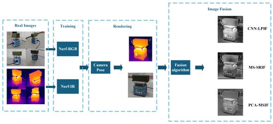
Figure 1.
Flow diagram of the registration, augmentation, and fusion processes for visible and infrared images.
2. Principles of NeRF Technology
The core idea of the neural radiance fields (NeRFs) model is to fit and represent a complex 3D scene using a fully connected neural network. The scene is modeled as a radiance field that, given a spatial location and a viewing direction, predicts the color and volume density at that point, enabling augmentation. Specifically, the scene is represented as a five-dimensional function, taking as input the 3D spatial coordinates and the 2D viewing direction , and outputting a color .
As the color varies with viewing angle, the color value depends on both the spatial location p and the viewing direction d. The parameter represents the volume density at a point, indicating the probability of ray termination, and depends only on the position p.
NeRF implicitly represents the entire scene’s features using a fully connected Multilayer Perceptron (MLP). First, the model processes the input 3D position p through a fully connected layer to produce the volume density and a high-dimensional feature vector. Next, the feature vector is concatenated with the viewing direction d and passed through another fully connected layer to predict the color c at that point. In essence, the continuous scene is encoded as a five-dimensional function as follows:
In a trained NeRF model, image synthesis from novel viewpoints is accomplished through volume rendering. Specifically, rays are cast from each target pixel through the scene, and the color of the pixel is obtained by integrating the color and volumetric density along the ray. This process is mathematically formulated as follows:
where denotes the accumulated transmittance, representing the probability that light is not absorbed along the path from a given point to the target point. It is computed as follows:
Due to the computational complexity of continuous integration, NeRF and related follow-up studies generally adopt a discrete stratified sampling approach for approximation. Specifically, the interval is partitioned into N equal sub-intervals, within each of which a sample point is randomly selected. The distance between two adjacent samples is denoted as . Through this discrete sampling scheme, the rendering equation can be approximated as follows:
where denotes the approximated accumulated transmittance. Using this discrete sampling approach, the expected color for each pixel is computed, and a fully rendered image is synthesized by aggregating all pixel values. To optimize the network, NeRF minimizes the error between predicted colors and ground-truth colors by using it as the loss function, which is defined as follows:
where denotes the color value predicted by the model, and represents the ground truth color. Figure 2 shows the flowchart of the NeRF algorithm, which is divided into four parts as follows: real image sampling, fully connected neural network training, 3D reconstruction, and augmented image generation [].

Figure 2.
Flowchart of the NeRF algorithm.
3. Infrared–Visible Image Generation
Images of the same scene under two modalities are acquired using a visible-light camera and an infrared camera. NeRF is used to independently train the 3D structures of the scene in the infrared and visible domains. Two neural networks are obtained, each encoding the infrared and visible characteristics of the scene, respectively. Given a new viewing direction, the generation of visible and infrared images is performed. This serves as a foundation for subsequent image fusion.
3.1. Scene Selection and Image Acquisition
3.1.1. Scene Selection
In terms of scene selection, to ensure the effectiveness and accuracy of dual-modal reconstruction using visible and infrared images, this study selects typical scenes characterized by pronounced temperature differences and rich visible-light texture details. The first is a real car in an outdoor environment. The second is a container model placed on a heating platform in a laboratory setting. These two types of scenes, respectively, simulate representative multimodal imaging scenarios under complex outdoor and controlled indoor conditions, as illustrated in Figure 3.
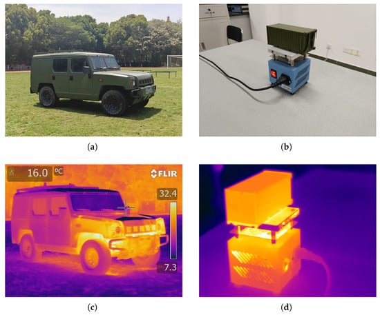
Figure 3.
Experimental setup: (a) Visible-light image of an actual vehicle in outdoor environment; (b) Visible-light image of a container model placed on a heating platform; (c) Thermal infrared image corresponding to (a); (d) Thermal infrared image corresponding to (b).
3.1.2. Image Acquisition Equipment and Methods
In this study, the image acquisition equipment includes a FLIR T620 infrared thermal imaging camera and a Realme GT5 visible-light camera, which were used to capture infrared and visible-light image data, respectively. The specific parameters are shown in Table 1.

Table 1.
Image acquisition equipment parameters.
A visible-light camera and an infrared camera were used to capture the same target during the experiment. The image acquisition did not require synchronization and could be conducted from different viewpoints.
In terms of image acquisition strategy, to obtain sufficient disparity information and enhance scene depth perception, images of the target were captured from 20 to 30 different viewpoints. Based on the results of the pre-experiment, the most effective angular interval for sampling was 30°, whereby one image was captured every 30°, achieving a full 360° surround acquisition of the target. Additionally, to fully capture the spatial structure of the object, several sets of image acquisition loops were performed from multiple overhead and low-angle viewpoints, thereby improving the completeness and accuracy of spatial reconstruction. A schematic diagram of the image acquisition is shown in Figure 4.
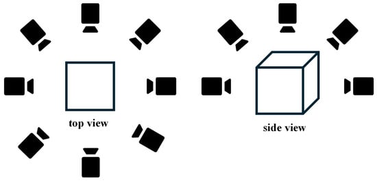
Figure 4.
Schematic diagram of shooting angle.
3.2. Improvement of NeRF Model
Infrared and visible-light images are captured in different spectral bands. Visible images primarily represent visual features such as surface color, texture, and shape, while infrared images primarily convey thermal characteristics and temperature distribution. Due to substantial differences in imaging principles and information representation, this study employs two improved models, NeRF-IR and NeRF-RGB, to process infrared and visible images, respectively.
This study builds upon the NeRFacto model developed in NeRFstudio, utilizing two improved models, NeRF-IR and NeRF-RGB, to implicitly reconstruct 3D models from visible and infrared image data. Through training iterations, 3D voxel information is encoded into fully connected neural networks. The network adopts a dual-input NeRF architecture, separately processing visible and infrared images. The two input channels simultaneously learn features of the scene from visible light and infrared thermal imagery, ultimately producing two fully connected network models: NeRF-IR for infrared scene reconstruction and NeRF-RGB for visible scene reconstruction [,]. For the two models, adjustments were made to their network architectures and parameters based on the data characteristics of different modalities.
For the two models, adjustments to their network structures and parameters were made based on the data characteristics of different modalities, as shown in Table 2.

Table 2.
Comparison of hyperparameter adjustments for NeRF-RGB and NeRF-IR.
Firstly, considering the inherent physical continuity and structural sensitivity of infrared images with respect to the temperature field, we significantly increased the weight of the distortion loss from 0.002 to 0.01. Infrared imaging primarily captures the thermal radiation emitted from object surfaces, where the temperature distribution typically exhibits strong spatial smoothness and physical consistency. Any geometric distortion or local artifact in the reconstructed image may be mistakenly interpreted as a thermal source, crack, or material boundary, thereby severely affecting the accuracy of downstream physical analysis. Therefore, in infrared image reconstruction, maintaining structural fidelity is more critical than in RGB images. In contrast, RGB images can tolerate moderate distortions in local texture or color without significantly compromising the overall visual or semantic understanding.
Secondly, in terms of network architecture design, we proposed a modality-aware framework that accounts for the representational differences between RGB and infrared images, aiming to balance reconstruction fidelity and computational efficiency. For the RGB model, given its rich color–space information and intricate texture patterns, the reconstruction task imposes higher representational demands. Accordingly, the backbone network is configured with hidden units = 128, and the color branch uses hidden dim = 128. Additionally, we increase the number of feature maps = 4 in each layer to enhance the network’s capacity for capturing high-frequency details. A denser ray-sampling strategy (coarse sampling) is also adopted to extract spatial variations in illumination and color more effectively, thereby improving image detail restoration accuracy.
In contrast, the infrared model focuses on capturing the spatial distribution of thermal intensities, which are relatively smooth and contain fewer texture details. To mitigate overfitting, especially in sparsely distributed thermal backgrounds, we reduce the complexity of the color branch and decrease the number of ray samples per view. Specifically, the sampling strategy is optimized by setting the number of fine samples per ray as fine sampling = (128, 64), which ensures structural consistency while significantly reducing redundant computation, thereby accelerating convergence.
Despite the lower sampling density in the infrared model, the increased weight on distortion loss effectively guides the model to maintain 3D structural coherence and physical plausibility throughout training. Overall, the modality-specific design not only considers the representational disparities between RGB and infrared modalities, but also demonstrates adaptive control over network complexity and sampling strategy. This ensures improved modeling accuracy and efficiency across both visible and infrared imaging scenarios.
3.3. New Perspective Registration Image Generation
To achieve image registration and further enable infrared–visible image fusion, this study addresses the alignment problem between generated visible and infrared images by using identical camera poses to ensure augmentation from the same field of view. Specifically, the two improved fully connected networks—NeRF-IR and NeRF-RGB—are trained to learn the implicit representation of the 3D scene, allowing for novel view synthesis via re-rendering. By inputting identical augmentation camera poses into the two trained NeRF models (infrared and visible), preliminary dual-modality image registration is achieved under new viewpoints.
3.3.1. Principle of Image Augmentation
The augmentation process consists of the following four main steps:
- Obtain a new camera pose:Camera pose includes both position and orientation. Before performing visible and infrared image augmentation, a camera pose different from the original captured images must be selected to generate augmented images from a new viewpoint.
- Cast rays from the new camera viewpoint:For each pixel during rendering, a ray is emitted from the virtual camera through the pixel and into the 3D scene space. To determine the color and opacity of each pixel, the ray must be sampled at its intersections with the 3D scene. Each ray can be represented aswhere o denotes the camera position, d is the ray direction, and t is the depth parameter along the ray, representing the distance from the camera origin to a specific point in the scene.
- Neural network prediction of color and density:By inputting the 3D coordinates x of the sampled point and its viewing direction d into the NeRF-IR and NeRF-RGB networks, the networks output the corresponding color c and volumetric density .
- Volume rendering for pixel color computation:The final pixel color along each ray is computed using the volumetric rendering equation as follows:where denotes the accumulated transmittance from the first sampled point to the current one, represents the density at the i-th sampled point, is the depth interval between adjacent samples, and is the color value of the i-th point.Finally, the pixel size parameter of the camera is determined, and the above steps are repeated for the rays emitted from each pixel to compute their color values. The resulting pixel colors are then aggregated to generate the augmented image [].
3.3.2. Principle of Image Registration
Directly fusing captured images can result in misalignment due to variations in shooting angles, positions, and lighting conditions. Such misregistration may cause noticeable seams or distortions in the composite image, compromising the naturalness and accuracy of the final result. Therefore, image registration becomes an indispensable step in the image fusion process, ensuring accurate alignment between images to eliminate misregistration and improve the quality of the fused result. As shown in Figure 5, when fused after cropping, the real infrared and visible images exhibit evident seams and distortions in non-registered images.
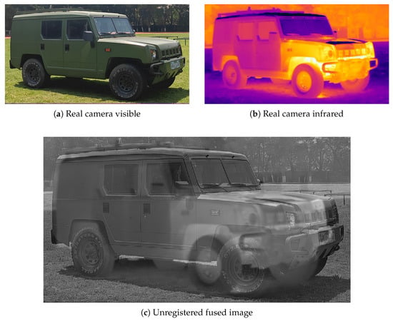
Figure 5.
Fusion of real-captured unaligned images.
Upon completion of the reconstruction, an efficient image registration strategy is proposed to achieve precise spatial matching between different modalities. Specifically, the augmented viewing angles were unified, allowing both visible and infrared images to be augmented under the same observation conditions, thus eliminating inconsistencies caused by differences in viewing angles. Next, to further enhance registration accuracy, the same intrinsic parameters and camera poses were set, ensuring that both visible and infrared images were augmented using identical camera configurations. This method successfully mitigates the influence of differences in camera parameters and view angles, leading to high-precision spatial registration between the augmented visible and infrared images. This ensures the consistency and accuracy of the images in the physical space.
Specifically, it is necessary to determine the transformation relationship between the visible camera coordinate system and the infrared camera coordinate system, as follows:
where denotes the world coordinate system and represents the visible-light camera coordinate system, is the translation vector, s is the scale factor, and is the rotation matrix, which can be expressed in terms of roll angle (), pitch angle (), and yaw angle () as follows:
The estimation of R, S, and T is achieved using the Umeyama algorithm, which performs point-to-point matching between the two point sets (visible point cloud) and (infrared point cloud), with the objective of computing an optimal rigid transformation that minimizes the relative distance between the two point sets after transformation, as follows:
The optimal rotation matrix R and translation vector T can be obtained by constructing the covariance matrix and applying singular value decomposition (SVD). The simulation results are shown in Figure 6: (a) and (b) depict the augmented camera views, presenting the scene-rendering effects under different modalities, and (c) and (d) display the spatial layout of the 3D scene, clearly showing the spatial relationship between the model and the camera in the scene. Through this registration strategy, more reliable and high-precision input data can be provided for subsequent image processing and fusion.
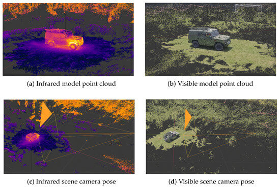
Figure 6.
3D point cloud and camera pose.
3.3.3. Image Registration Results
To achieve precise spatial alignment between infrared and visible-light modalities, we first export the reconstructed 3D point cloud model based on NeRF-IR in PLY format, facilitating subsequent analysis and registration processing. Considering non-ideal initial conditions in real-world scenarios (e.g., noise interference, occlusions, and viewpoint discrepancies), a series of robustness-enhancing preprocessing steps were introduced. Specifically, we perform spatial cropping on the reconstructed point cloud to extract the target region subset, followed by point cloud downsampling, normal estimation, and feature enhancement using Fast Point Feature Histograms (FPFH), thereby improving point correspondence quality and registration stability.
Figure 7 illustrates the extracted visible and infrared point cloud models used in the experiments. To focus on key geometric structures, we crop the exported 3D point clouds and retain only the local region containing the target object.
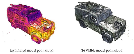
Figure 7.
Cropped visible and infrared point cloud models reconstructed from NeRF-IR.
Next, to achieve spatial alignment of multimodal point clouds, we adopt a registration method based on feature matching and rigid transformation estimation. This approach aims to estimate the transformation between the infrared point cloud and the visible point cloud, which consists of three components: a translation vector T that describes the positional offset between point cloud centroids, a scaling factor s to address size discrepancies between models, and a rotation matrix R to capture orientation differences between coordinate systems. Taking an outdoor vehicle target as an example, Figure 8 compares the visible and infrared point clouds before and after registration within a unified coordinate system.
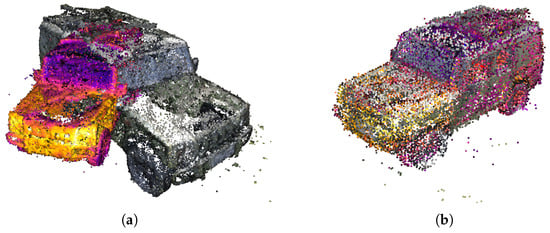
Figure 8.
Point cloud images before and after registration. (a) Comparison of unaligned multimodal point clouds. (b) Registered alignment result of infrared and visible point clouds.
As shown in the figure, the registered infrared point cloud exhibits high geometric consistency with the visible point cloud, indicating that the proposed method achieves accurate alignment performance under complex multimodal conditions.
At the parameter level, the estimated transformation results obtained from the registration process are summarized in Table 3.

Table 3.
Estimated transformation parameters for multimodal point cloud registration.
In terms of spatial registration accuracy, the proposed method achieves an 86.13% point-matching ratio in typical test scenarios, demonstrating high precision. In comparison with state-of-the-art (SOTA) methods, LoFTR [] achieves an AUC@5° of 52.8% in standard pose estimation tasks, R2D2 [] reports a pose accuracy of 62.7%, and D2-Net [] obtains a matching accuracy of 78.4%. Although these approaches perform well in image registration tasks, they often struggle with multimodal point cloud alignment due to texture inconsistencies and viewpoint variations.
In contrast, the point cloud registration method adopted in this work, based on geometric consistency, integrates both coarse pre-alignment and rigid optimization strategies. This effectively suppresses cross-modality error propagation and offers a significant advantage in registration accuracy, making it particularly suitable for infrared–visible fusion scenarios dominated by structural information.
3.4. Image Augmentation Results and Analysis
3.4.1. Model Performance Optimization Verification
During the NeRF training process, the dataset was split into 90% for training and 10% for testing to ensure that the model’s generalization ability could be evaluated on unseen viewpoints. During testing, real captured images from the test set were selected, and their corresponding camera poses were input into the model to generate synthetic images under the same viewpoint for similarity comparison. Two experimental scenes were selected: a car on a playground and a container on a heating platform. The control group employed the NeRFacto model from the NeRFstudio community, whereas the experimental group consisted of an enhanced NeRF-RGB model tailored for visible-light scenes and a modified NeRF-IR model adapted for infrared scenarios [].
The NeRFacto method, as an improved algorithm, has become one of the widely adopted benchmark methods in the field of 3D scene reconstruction due to its effective balance between training efficiency and rendering quality. Additionally, the NerFacto method exhibits strong scalability and adaptability, making it suitable for scene reconstruction tasks of varying scales and complexities. Given these advantages, this study selects the NeRFacto method as the experimental control group to objectively evaluate the performance of the newly proposed algorithm. This choice aligns with the standard benchmarking practices in the field of computer vision, ensuring the reliability and comparability of the experimental results.
Both the proposed NeRF-RGB and NeRF-IR models are implemented based on the open-source framework Nerfstudio and trained/tested on a computing platform equipped with an NVIDIA GeForce RTX 4060 Laptop GPU. The average training time per session is approximately 25 min, indicating high training efficiency. The developed models and related source codes have been publicly released to facilitate academic exchange and further research.
During the experiment, a real car and a container model on a heating platform were selected as the scene, with augmented images of different models shown in Figure 9. In Figure 9, (a), (d), and (g) are real-captured images, (b), (e), and (h) are augmented images generated using the NeRFacto model, (c) is an augmented image generated by the NeRF-IR model, and (f) and (i) are augmented images generated by the NeRF-RGB model.

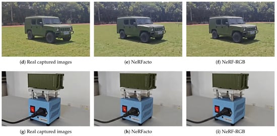
Figure 9.
Augmented infrared and visible-light images from different models.
To assess the realism of the augmented images, multiple metrics were employed to evaluate the similarity between the augmented and real captured images. These metrics include structural similarity index (SSIM), cosine similarity, mutual information, peak signal-to-noise ratio (PSNR), and histogram similarity. Table 4 presents the simulation similarity metrics between enhanced images generated by different models and their corresponding real images.

Table 4.
Image similarity metrics for different augmented models.
Table 5 shows the improvement of similarity metrics obtained by comparing the proposed enhancement model with the NeRFacto model.

Table 5.
Improvement percentages of similarity metrics.
Evaluation of Model Enhancement Results:
- NeRF-IR Model (Car Scene)The SSIM and PSNR scores of the NeRF-IR model improved by 7.90% and 18.44%, demonstrating considerable enhancement in both visual quality and structural similarity, with clearer and more detailed images. Mutual information increased by 28.63%, indicating that the refined model captures a greater amount of meaningful content. Histogram similarity rose by 25.31%, which shows that color channels are better distributed, enhancing the natural appearance of colors.
- NeRF-RGB Model (Container Scene)A 12.60% increase in SSIM for the NeRF-RGB model highlights its significant improvement in preserving structural details. Mutual information rose by 32.72%, demonstrating a stronger capacity for capturing essential scene information.The PSNR improved by 26.06%, reflecting reduced noise and improved image fidelity. A 14.95% gain in histogram similarity reflects better color consistency and precision in the augmented images.
The enhanced NeRF-IR and NeRF-RGB models demonstrated consistent improvements in 331 major metrics such as PSNR, SSIM, mutual information, and histogram similarity. These 332 enhancements not only improved image quality and structural fidelity, but also significantly increased the informational content and visual naturalness of the 333 augmented images.
3.4.2. Validation of Model Augmentation Capability Under Restricted Perspective
To validate the generalization ability and limitations of the proposed NERF-IR model under constrained viewing conditions, we designed a set of experiments simulating practical application scenarios. Specifically, only partial angular views were used for training, addressing the common real-world challenge of lacking full 360° data acquisition. In this experiment, multiview images were collected within an azimuth range of approximately 120° from the side of the target model, as illustrated in Figure 10.
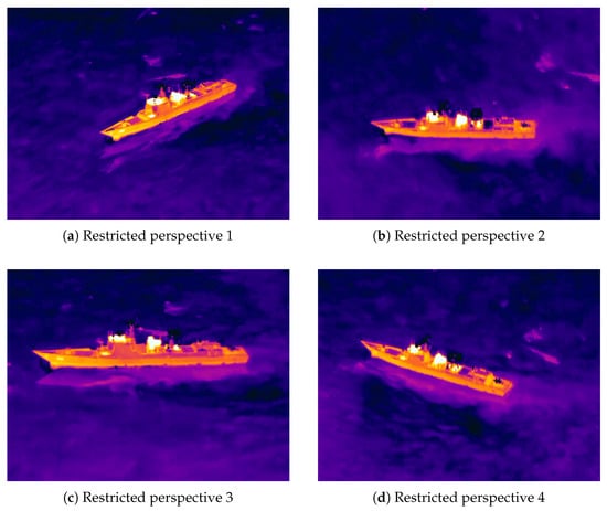
Figure 10.
Captured images from different directions within a limited viewing angle.
Based on these limited observations, the improved NERF-IR model was employed to perform 3D reconstruction and synthesize infrared images within the real captured view range (i.e., within the 120° sector). A qualitative comparison between the synthesized and the real infrared images is presented in Figure 11. From the visual results, it can be observed that the synthesized images maintain high consistency with the real ones in terms of structural detail restoration and thermal feature representation, preliminarily validating the model’s effectiveness under limited view conditions.
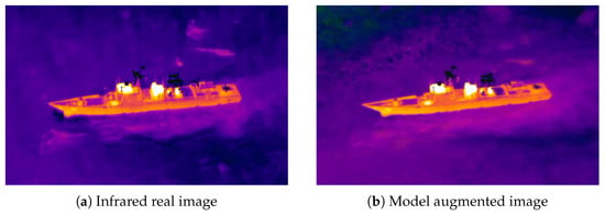
Figure 11.
Comparison between real shooting and model augmented images.
To further quantify the model’s performance in novel view synthesis tasks, several mainstream image quality assessment metrics were adopted, including structural similarity index (SSIM), peak signal-to-noise ratio (PSNR), cosine similarity, mutual information (MI), and histogram similarity. The evaluation results between the synthesized and real images are summarized in Table 6.

Table 6.
Evaluation metrics for image similarity under novel views.
From both quantitative and qualitative analyses, it is evident that the NERF-IR model demonstrates strong 3D reconstruction capabilities and high-quality infrared image synthesis even under limited-view training conditions. Notably, in previously unseen views, the synthesized images achieve high scores across multiple metrics, indicating the model’s robust spatial generalization and thermal structure preservation abilities. These findings convincingly validate the scalability and practical value of NeRF-based approaches in infrared image modeling and generation under data-limited scenarios, offering a promising new direction for infrared perception and reconstruction tasks in complex or inaccessible environments.
4. Image Fusion
4.1. Image Fusion Method
The goal of visible and infrared image fusion is to integrate information from distinct spectral modalities, resulting in an image that includes the sharp texture and edge details of the visible spectrum, while simultaneously embedding the thermal data captured by infrared imaging.
In this study, three representative image fusion algorithms are selected—MS-SRIF, PCA-MSIF, and CNN-LPIF—corresponding to the three mainstream methodological paradigms in current image fusion research; namely, multiscale sparse representation-based methods, statistical subspace transformation-based methods, and deep-learning-based end-to-end approaches.
MS-SRIF (Multiscale Sparse Representation Image Fusion) adopts a fusion strategy based on multiscale sparse modeling. By encoding images in multiple scale spaces using sparse representation, it effectively preserves edge structures and texture details. This method integrates classical ideas from sparse modeling and multiscale decomposition, making it particularly suitable for heterogeneous information distribution scenarios in infrared and visible image fusion. It demonstrates stable performance in maintaining image details and energy preservation. PCA-MSIF (PCA-Based Multisource Image Fusion) represents the statistical subspace transformation-based approach. Its core idea is to apply principal component analysis (PCA) to compress and reconstruct multisource image features, thereby achieving efficient fusion and dimensionality reduction. Due to its high computational efficiency and implementation simplicity, it is well-suited for applications requiring real-time performance.In contrast, CNN-LPIF (CNN-Based Low-level Pixel-Wise Image Fusion) belongs to the category of end-to-end fusion methods based on neural networks. This method automatically learns fusion strategies at the pixel level through convolutional neural networks, allowing it to handle nonlinear and complex cross-modal relationships. Without the need for explicitly designed fusion rules, it adaptively optimizes model parameters during the data-driven training process, thus exhibiting strong adaptability and generalization capabilities. It is particularly applicable to multimodal image fusion tasks involving significant structural differences.
In summary, these three algorithms not only encompass the main research paradigms in the field of image fusion, but also provide a solid foundation for in-depth comparison between traditional methods and deep learning approaches in multimodal image fusion, offering strong representativeness and analytical value.
4.1.1. Multiscale Sparse Representation Image Fusion
First, an image fusion algorithm based on multiscale sparse representation is proposed. It integrates multiscale transformation and sparse coding techniques. The images are decomposed at multiple scales, and features are fused according to specific criteria.This method retains detailed information from different source images. Meanwhile, the method helps to reduce noise in the fused image.The underlying principle is as follows:
- (1)
- Sparse Representation
In image processing, the sparse representation method represents a signal x as a sparse linear combination using a predefined dictionary matrix D, as follows:
where is a sparse coefficient vector, and D is a dictionary matrix learned through pre-training. Sparse dictionary representation generates a dictionary basis from training samples, enabling each sample to be represented by a sparse vector. The dictionary D, trained on numerous image patches, is used for sparse representation of visible and infrared images to reduce redundant information and denoise.
- (2)
- Multiscale Decomposition
To capture hierarchical information from both visible and infrared images, this study employs a multiscale transformation technique. Specifically, Laplacian pyramid decomposition is used to decompose each input image into L layers, with each layer producing several low- and high-frequency sub-bands. The k-th sub-band in the l-th layer is denoted as follows:
where denotes the number of sub-bands at layer l, and and correspond to the visible and infrared modalities, respectively.
Each sub-band is then partitioned into overlapping patches. Let the j-th patch from the k-th sub-band at the l-th level be denoted by . Sparse coding is performed for each patch using a pre-trained dictionary D, and the sparse coefficient vector is obtained by solving a constrained least-squares problem:
where, denotes the number of non-zero elements in , and is a threshold controlling the sparsity. Since this is an NP-hard problem, the Orthogonal Matching Pursuit (OMP) algorithm is used for approximation.
- (3)
- Sparse Coefficient Fusion
To fuse sparse coefficients from corresponding patches in the two modalities, a max-absolute-value selection rule is applied. For each index , the fused coefficient is defined as follows:
After fusing the sparse coefficients for all sub-bands, each fused sub-band is reconstructed via sparse representation. Finally, the inverse Laplacian pyramid transform is applied to the set of reconstructed sub-bands to synthesize the final fused image [].
4.1.2. PCA-Enhanced Multiscale Image Fusion
This method analyzes the gradients and second-order derivatives of images to extract base and detail layers. Fusion is performed via Principal Component Analysis (PCA), and the fused base and detail layers are finally reconstructed to produce an optimized fused image. The process is detailed as follows:
- (1)
- Multiscale Decomposition of Base and Detail Layers
The base layer containing structural information is obtained through an iterative process that computes image gradients and second-order derivatives, combined with adaptive weighting (based on gradient magnitude) to progressively smooth the image and reduce noise. The high-frequency components preserving edge and texture details are then extracted by subtracting the base layer from the original image.
where denotes the base layer, denotes the detail layer, and is a smoothing function based on partial differential operators.
- (2)
- Fusion and Reconstruction of Base and Detail Layers
PCA is applied to fuse the base and detail layers. The covariance matrix is calculated and decomposed to obtain eigenvalues and eigenvectors, from which the principal components are selected according to the variance they represent.
The principal eigenvector is then normalized to obtain the fusion weights:
The detail layers are fused using the derived PCA weights:
For the base layers, average fusion is used to preserve the overall structure:
Finally, the fused image F is reconstructed by combining the fused base and detail layers:
4.1.3. CNN-Enhanced Laplacian Pyramid Image Fusion
This method combines convolutional neural networks (CNN) and the Laplacian pyramid for fusing visible and infrared dual-modal images. It enables the estimation of the importance of local patches from both modalities and assigns fusion weights accordingly.
- (1)
- Focus Map Extraction Using CNN
A four-layer CNN is employed to generate a focus map representing the fusion weights. This network performs convolution, pooling, and classification using a softmax layer to determine which image patch—visible or infrared—contains more important information. The convolutional operation is defined as follows:
where I denotes the input image, represents the i-th convolution kernel, is the bias term, and ReLU is the activation function.
The CNN has four layers, with increasing channel dimensions while maintaining spatial size, allowing it to learn increasingly complex structures and high-level features. The final classification is performed using a softmax layer as follows:
The classifier assigns a probability of importance to each patch in the image. These probabilities are mapped back to the original image using a sliding window and averaged to form the final focus map, which determines the fusion weights.
- (2)
- Laplacian Pyramid Construction and Image Reconstruction
A Gaussian pyramid is first constructed for each image by repeatedly applying Gaussian blurring and downsampling:
where, is the l-th level of the Gaussian pyramid, built using a Gaussian kernel. Each layer is downsampled by a factor of two, capturing image structures at multiple scales.
The Laplacian pyramid is then constructed by subtracting adjacent Gaussian pyramid layers as follows:
represents the Laplacian image at level l, and the upsampling operation resizes to match for pixel-wise subtraction. The final Gaussian layer is preserved as the residual as follows:
A weight pyramid is generated from the focus map. For each Laplacian layer from the visible and infrared images, fusion is performed as follows:
where, denotes the weight corresponding to the importance of the visible image. After all Laplacian layers are fused, the final fused image is reconstructed from the bottom up as follows [,]:
4.2. Result Analysis
4.2.1. Image Augmentation and Fusion Results
In this work, we acquired multimodal training datasets via on-site shooting, comprising both visible-light and infrared images. Specifically, the infrared images were captured at 8:00 p.m., after the vehicle had been started and running for 30 min to fully reveal its thermal characteristics. Conversely, the visible-light images were captured at noon (12:00 p.m.) on the same day under natural daylight, documenting the vehicle’s appearance. It should be noted that the vehicle’s position remained unchanged during image capture to ensure spatial consistency of the scene, with the captured images shown in Figure 12 and Figure 13.

Figure 12.
Infrared images of the car captured from different angles.

Figure 13.
Visible-light images of the car captured from different angles.
However, due to differences in imaging time and modality, the original visible and infrared images exhibited significant discrepancies in spatial distribution and viewpoint. This made it difficult to achieve effective registration between the two without preprocessing. Thus, the fusion of multimodal information becomes more challenging, which underscores the importance of this study.
To address this issue, this study proposes a method based on an improved NeRF model, designing NeRF-RGB and NeRF-IR models specifically for visible (RGB) and infrared (IR) images. The models are trained using infrared and visible images from selected directions to learn the radiance field distribution in the 3D scene, enabling spatial reconstruction under different modalities. After reconstruction, we unify the augmented viewpoints and set identical intrinsic parameters and camera poses to ensure precise spatial alignment between the generated visible and infrared images. The resulting dual-modal images not only achieve high-precision registration, but also provide a reliable data foundation for subsequent multimodal fusion and high-level semantic understanding. The point cloud image of the spatially reconstructed car in infrared modality is shown in Figure 14.
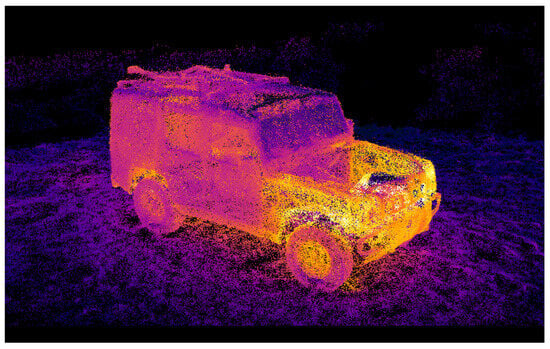
Figure 14.
Point cloud reconstruction image.
Using identical camera parameters and pose settings, precisely spatially registered dual-modal images were generated, as shown in Figure 15, where (a) is the augmented infrared image and (b) is the augmented visible-light image.
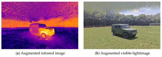
Figure 15.
Precisely registered dual-modal images.
Images from novel viewpoints were obtained through view augmentation, upon which visible–infrared image fusion was performed. Three different visible–infrared fusion methods were employed, with the fusion results shown in Figure 16. (a)–(c) are the fused images obtained by three different methods MS-SRIF, PCA-MSIF, and CNN-LPIF, respectively, while (d), (e) are the augmented bimodal images. Observations reveal that these methods maintain complementary thermal information and image details while demonstrating varying fusion performance and visual effects.
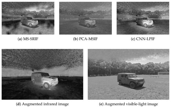
Figure 16.
Results of different visible–infrared image fusion methods.
4.2.2. Analysis of Image Fusion Results
In order to evaluate the fusion performance of visible and infrared images, eleven metrics, including MV, SD, EN, SF, AvgGradient, EdgeIntensity, QABF, 5MI, PSNR, SSIM, and RMSE, were used to assess the fusion quality, as shown in Table 7.

Table 7.
Evaluation metrics of different fusion methods.
Based on the subjective visual quality of the reconstructed images and the objective evaluation metrics of the fused images in the comprehensive experiments, it can be concluded that all three image fusion methods demonstrate a certain degree of effectiveness in the task of fusing visible and infrared images, although their respective advantages and suitable application scenarios differ.
The CNN-LPIF method exhibits superior performance in preserving edge structures and local gradients, as reflected by higher image entropy (EN = 7.15), spatial frequency (SF = 8.79), and average gradient (AvgGradient = 54.54). This makes it suitable for applications requiring high structural fidelity. However, it performs slightly worse than other methods in terms of mutual information (MI = 0.31) and structural similarity (SSIM = 0.61), indicating room for improvement in overall fusion consistency. The PCA-MSIF method shows advantages in image smoothness (lower SD = 22.98) and structural consistency metrics (PSNR = 14.24, SSIM = 0.62), producing fused images with better visual balance. This makes it suitable for application scenarios with low noise and simple edge structures. Nevertheless, its performance in preserving image details is less satisfactory, as evidenced by lower image entropy (EN = 6.41) and edge intensity (EdgeIntensity = 17.89), limiting its applicability in detail-sensitive tasks. The MS-SRIF method demonstrates the best performance in preserving image details and textures. Metrics such as image entropy (EN = 7.38), edge intensity (EdgeIntensity = 26.55), and MI (0.50) are higher than or comparable to CNN-LPIF, while maintaining lower RMSE and cross-entropy values. This indicates that MS-SRIF achieves a good balance between structural integrity and detail representation, making it well-suited for infrared/visible image fusion scenarios that demand high detail preservation.
Additionally, a typical characteristic of NeRF-generated images is their high spatial continuity and smoothness. This smoothness arises from its volume-rendering-based image generation mechanism, which effectively suppresses noise and inconsistencies, but may also attenuate high-frequency information such as textures and edges. In image fusion tasks, this characteristic significantly impacts the performance of different fusion algorithms. Compared with the other two methods, CNN-LPIF can adaptively learn pixel-level fusion strategies and possesses stronger modeling capabilities for nonlinear relationships and cross-modal differences. When dealing with the smoothness of NeRF images, CNN-LPIF can automatically extract latent differences in a data-driven manner, helping to mitigate the loss of details and exhibiting better robustness and generalization, thereby achieving superior fusion performance.
By introducing NeRF-based data augmentation, it becomes possible to generate multimodal, multiview, and multitemporal data, fundamentally addressing traditional issues in image fusion such as temporal misalignment, large viewpoint differences, and registration difficulties between different modalities, while the spatial continuity and smoothness characteristics of NeRF-generated images present new adaptation challenges for conventional fusion algorithms, they provide a more structured data distribution that benefits deep-learning-based fusion approaches. This study offers both theoretical foundations and practical support for enhancing the robustness and generality of multimodal image fusion techniques.
5. Conclusions
This study proposes a multimodal image registration and fusion technique based on an improved NeRF method, which demonstrates significant advantages in addressing the registration problem between visible light and infrared images. By introducing a geometry-consistent point cloud registration method, combined with pre-registration and rigid optimization strategies, we achieved an 86.13% point cloud matching rate in typical test scenarios. This significantly outperforms existing state-of-the-art (SOTA) algorithms such as LoFTR, R2D2, and D2-Net; while these methods excel in single-modal registration tasks, they often exhibit instability when dealing with multimodal point cloud alignment due to perspective changes and texture differences. In contrast, the proposed method effectively suppresses cross-modal error propagation, maintaining high-precision registration performance, especially in infrared–visible fusion scenarios dominated by structural information.
The improved NERF-IR and NERF-RGB models show significant improvements across multiple key metrics when compared to the widely recognized NERFacto model, particularly in terms of image quality and structural similarity. The NERF-IR model demonstrated a 7.90% improvement in SSIM and an 18.44% improvement in PSNR, indicating a notable enhancement in image clarity and detail. The increase in mutual information highlights the model’s ability to capture more useful information. The NERF-RGB model also exhibited substantial improvements across several metrics, particularly in noise reduction and information extraction, with SSIM and PSNR improving by 12.60% and 26.06%, respectively. These improvements result in more natural and accurate color distribution in the generated images. Overall, the improved models not only enhance the visual quality and structural restoration capabilities of the images, but also increase their information content, enabling the rendered images to exhibit higher naturalness and realism in multimodal fusion tasks.
Additionally, the images generated by NeRF exhibit high spatial continuity and smoothness, which, while presenting challenges in traditional image fusion methods, can be effectively addressed by combining deep-learning-based fusion methods such as CNN-LPIF. These methods adaptively handle pixel-level fusion strategies, reducing detail loss and thus achieving superior fusion quality and robustness compared to other traditional methods.
Specifically, to address the challenge of obtaining accurately registered images for visible light and infrared dual-modal fusion, this study employs an improved NeRF method for 3D scene reconstruction and image enhancement using visible light and infrared images captured from multiple angles. The study utilizes uniform camera parameters and pose settings for both infrared and visible light point cloud scenes to achieve spatially registered dual-modal image data, which is then used for image fusion. This approach effectively resolves the difficulty of precise registration between visible light and infrared images during acquisition, providing a high-quality data foundation and an accurate registration solution for subsequent multimodal image fusion. The main innovation of this work lies in the following:
- By constructing a dual-model architecture of NERF-RGB (visible scene) and NERF-IR (infrared scene), the performance of multimodal image augmentation was significantly improved. With network structure adjustment and hyperparameter optimization, NERF-IR achieved a 28.63% increase in mutual information (MI) and an 18.44% improvement in PSNR for infrared image reconstruction, while NERF-RGB achieved 12.60% and 26.06% improvements in SSIM and PSNR, respectively, for visible-light scenes.
- Various image fusion methods, such as MS-SRIF, PCA-MSIF, and CNN-LPIF, were employed. Metric analysis shows that different algorithms exhibit advantages in edge detail preservation, gradient retention, image smoothness, and noise resistance, and their applicable scenarios are discussed.
- After 3D scene reconstruction, new camera parameters and pose settings were applied to generate augmented images, providing an innovative solution for multimodal image registration. This method enables the generation of image information from unknown viewpoints based on known infrared/visible data, overcoming the dependence of traditional methods on data completeness.
Author Contributions
Conceptualization, Y.S., Y.F., and H.T.; methodology, Y.F., and W.J.; software, Y.S., and C.Z.; validation, Y.S.; formal analysis, Y.F., W.J., H.T., and S.W.; investigation, Y.F., W.J., H.T., and S.W.; resources, C.Z.; data curation, Y.S., W.J., H.T., and S.W.; writing—original draft preparation, Y.S.; writing—review and editing, Y.S.; supervision, Y.S., W.J., and C.Z.; project administration, Y.F., W.J., and C.Z.; funding acquisition, Y.F., W.J., and C.Z. All authors have read and agreed to the published version of the manuscript.
Funding
This research is funded by the Key Projects of the Foundation Strengthening Program, grant number 2023-JJ-0604.
Data Availability Statement
The data presented in this study are available on request from the corresponding author.
Conflicts of Interest
The authors declare no conflicts of interest.
References
- Ma, J.; Ma, Y.; Li, C. Infrared and visible image fusion methods and applications: A survey. Inf. Fusion 2019, 45, 153–178. [Google Scholar] [CrossRef]
- Qi, J.; Abera, D.E.; Fanose, M.N.; Wang, L.; Cheng, J. A deep learning and image enhancement based pipeline for infrared and visible image fusion. Neurocomputing 2024, 578, 127353. [Google Scholar] [CrossRef]
- Qi, B.; Li, Q.; Zhang, Y.; Zhao, Q.; Qiao, B.; Shi, J.; Lv, Z.; Li, G. Infrared and visible image fusion via sparse representation and adaptive dual-channel PCNN model based on co-occurrence analysis shearlet transform. IEEE Trans. Instrum. Meas. 2025, 74, 5004815. [Google Scholar] [CrossRef]
- Ma, J.; Zhao, J.; Ma, Y.; Tian, J. Non-rigid visible and infrared face registration via regularized Gaussian fields criterion. Pattern Recognit. 2015, 48, 772–784. [Google Scholar] [CrossRef]
- Kong, S.G.; Heo, J.; Boughorbel, F. Multiscale Fusion of Visible and Thermal IR Images for Illumination-Invariant Face Recognition. Int. J. Comput. Vis. 2007, 71, 215–233. [Google Scholar] [CrossRef]
- Gao, J.; Jiang, G.; Gao, C. A method for calibrating multi-camera systems based on sparse reconstruction of a 3D object. Measurement 2025, 240, 115561. [Google Scholar] [CrossRef]
- Chen, X.; Zhai, G.; Wang, J.; Hu, C.; Chen, Y. Color Guided Thermal Image Super Resolution. In Proceedings of the 2016 Visual Communications and Image Processing (VCIP), Chengdu, China, 27–30 November 2016. [Google Scholar]
- Smith, J.; Johnson, L. An iterative image registration technique with an application to stereo vision. J. Comput. Vis. 1981, 123–145. [Google Scholar]
- Ma, J.; Jiang, J.; Liu, C.; Li, Y. Feature guided Gaussian mixture model with semi-supervised EM and local geometric constraint for retinal image registration. Inf. Sci. 2017, 417, 128–142. [Google Scholar] [CrossRef]
- Clausi, D.A.; Wong, A. ARRSI: Automatic Registration of Remote-Sensing Images. IEEE Trans. Geosci. Remote Sens. 2007, 45, 1483–1493. [Google Scholar]
- Mildenhall, B.; Srinivasan, P.P.; Tancik, M.; Barron, J.T.; Ramamoorthi, R.; Ng, R. NERF: Representing scenes as neural radiance fields for view synthesis. Commun. ACM 2022, 65, 99–106. [Google Scholar] [CrossRef]
- Yu, A.; Fridovich-Keil, S.; Tancik, M.; Chen, Q.; Recht, B.; Kanazawa, A. Plenoxels: Radiance Fields without Neural Networks. arXiv 2021, arXiv:2112.05131. [Google Scholar] [CrossRef]
- Zhang, K.; Riegler, G.; Snavely, N.; Koltun, V. NERF++: Analyzing and Improving Neural Radiance Fields. arXiv 2020, arXiv:2010.07492. [Google Scholar]
- Turki, H.; Ramanan, D.; Satyanarayanan, M. Mega-NERF: Scalable Construction of Large-Scale NERFs for Virtual Fly-Throughs. arXiv 2022, arXiv:2112.10703. [Google Scholar]
- Nguyen, T.A.Q.; Bourki, A.; Macudzinski, M.; Brunel, A.; Bennamoun, M. Semantically-aware Neural Radiance Fields for Visual Scene Understanding: A Comprehensive Review. arXiv 2024, arXiv:2402.11141. [Google Scholar] [CrossRef]
- Yu, A.; Ye, V.; Tancik, M.; Kanazawa, A. pixelNERF: Neural Radiance Fields from One or Few Images. arXiv 2021, arXiv:2012.02190. [Google Scholar]
- Hao, F.; Shang, X.; Li, W.; Zhang, L.; Lu, B. VT-NERF: Neural radiance field with a vertex-texture latent code for high-fidelity dynamic human-body rendering. IET Comput. Vis. 2023, 19, 1. [Google Scholar] [CrossRef]
- Wang, C.; Chai, M.; He, M.; Chen, D.; Liao, J. CLIP-NERF: Text-and-Image Driven Manipulation of Neural Radiance Fields. arXiv 2022, arXiv:2112.05139. [Google Scholar]
- Wang, Y.; Fang, S.; Zhang, H.; Li, H.; Zhang, Z.; Zeng, X.; Ding, W. UAV-ENERF: Text-Driven UAV Scene Editing with Neural Radiance Fields. IEEE Trans. Geosci. Remote Sens. 2024, 62, 5615514. [Google Scholar] [CrossRef]
- Levy, D.; Peleg, A.; Pearl, N.; Rosenbaum, D.; Akkaynak, D.; Korman, S.; Treibitz, T. SeaThru-NeRF: Neural Radiance Fields in Scattering Media. In Proceedings of the IEEE/CVF Conference on Computer Vision and Pattern Recognition, Vancouver, BC, Canada, 17–24 June 2023; pp. 56–65. [Google Scholar]
- Barron, J.T.; Mildenhall, B.; Tancik, M.; Hedman, P.; Martin-Brualla, R.; Srinivasan, P.P. Mip-NeRF: A Multiscale Representation for Anti-Aliasing Neural Radiance Fields. arXiv 2021, arXiv:2103.13415. [Google Scholar]
- Yu, A.; Li, R.; Tancik, M.; Li, H.; Ng, R.; Kanazawa, A. PlenOctrees for Real-time Rendering of Neural Radiance Fields. arXiv 2021, arXiv:2103.14024. [Google Scholar]
- Müller, T.; Evans, A.; Schied, C.; Keller, A. Instant Neural Graphics Primitives with a Multiresolution Hash Encoding. arXiv 2022, arXiv:2201.05989. [Google Scholar] [CrossRef]
- Ma, J.; Chen, C.; Li, C.; Huang, J. Infrared and visible image fusion via gradient transfer and total variation minimization. Inf. Fusion 2016, 31, 100–109. [Google Scholar] [CrossRef]
- Goyal, B.; Dogra, A.; Agrawal, S.; Sohi, B.S.; Sharma, A. Image denoising review: From classical to state-of-the-art approaches. Inf. Fusion 2020, 55, 220–244. [Google Scholar] [CrossRef]
- Zhang, Z.; He, C.; Wang, H.; Cai, Y.; Chen, L.; Gan, Z.; Huang, F.; Zhang, Y. Fusion of infrared and visible images via multi-layer convolutional sparse representation. J. King Saud Univ. Comput. Inf. Sci. 2024, 36, 102090. [Google Scholar] [CrossRef]
- Jin, Q.; Tan, S.; Zhang, G.; Yang, Z.; Wen, Y.; Xiao, H.; Wu, X. Visible and Infrared Image Fusion of Forest Fire Scenes Based on Generative Adversarial Networks with Multi-Classification and Multi-Level Constraints. Forests 2023, 14, 1952. [Google Scholar] [CrossRef]
- Zhang, Y.; Liu, Y.; Sun, P.; Yan, H.; Zhao, X.; Zhang, L. IFCNN: A general image fusion framework based on convolutional neural network. Inf. Fusion 2020, 54, 99–118. [Google Scholar] [CrossRef]
- Li, S.; Wang, G.; Zhang, H.; Zou, Y. SDRSwin: A Residual Swin Transformer Network with Saliency Detection for Infrared and Visible Image Fusion. Remote Sens. 2023, 15, 4467. [Google Scholar] [CrossRef]
- Zhang, X.; Ye, P.; Xiao, G. VIFB: A Visible and Infrared Image Fusion Benchmark. arXiv 2020, arXiv:2002.03322. [Google Scholar] [CrossRef]
- Akbari Haghighat, M.B.; Aghagolzadeh, A.; Seyedarabi, H. A non-reference image fusion metric based on mutual information of image features. Comput. Electr. Eng. 2011, 37, 744–756. [Google Scholar] [CrossRef]
- Wang, S.; Sun, Z.; Li, Q. High-to-low-level feature matching and complementary information fusion for reference-based image super-resolution. Vis. Comput. 2024, 40, 99–108. [Google Scholar] [CrossRef]
- Kumar, V.; Bawa, V.S. No reference image quality assessment metric based on regional mutual information among images. arXiv 2019, arXiv:1901.05811. [Google Scholar]
- You, C.; Liu, Y.; Zhao, B. A Novel Quality Metric for Image Fusion Based on Mutual Information and Structural Similarity. J. Comput. Inf. Syst. 2014, 10, 1651–1657. [Google Scholar]
- Liu, Y.; Chen, X.; Cheng, J.; Peng, H.; Wang, Z. Infrared and visible image fusion with convolutional neural networks. Int. J. Wavelets Multiresolut. Inf. Process. 2018, 16, 1850018. [Google Scholar] [CrossRef]
- Liu, Y.; Chen, X.; Peng, H.; Wang, Z. Multi-focus image fusion with a deep convolutional neural network. Inf. Fusion 2017, 36, 191–207. [Google Scholar] [CrossRef]
- Liu, Y.; Liu, S.; Wang, Z. A general framework for image fusion based on multi-scale transform and sparse representation. Inf. Fusion 2015, 24, 147–164. [Google Scholar] [CrossRef]
- Li, Y.; Liu, G.; Bavirisetti, D.P.; Gu, X.; Zhou, X. Infrared-visible image fusion method based on sparse and prior joint saliency detection and LatLRR-FPDE. Digit. Signal Process. 2023, 134, 103910. [Google Scholar] [CrossRef]
- Sun, J.; Shen, Z.; Wang, Y.; Bao, H.; Zhou, X. LoFTR: Detector-Free Local Feature Matching with Transformers. In Proceedings of the IEEE/CVF Conference on Computer Vision and Pattern Recognition (CVPR), Nashville, TN, USA, 19–25 June 2021; pp. 8922–8931. [Google Scholar]
- Revaud, J.; De Souza, C.; Humenberger, M.; Weinzaepfel, P. R2D2: Reliable and Repeatable Detector and Descriptor. Adv. Neural Inf. Process. Syst. 2019, 32, 12405–12415. [Google Scholar]
- Dusmanu, M.; Rocco, I.; Pajdla, T.; Pollefeys, M.; Sivic, J.; Torii, A.; Sattler, T. D2-Net: A Trainable CNN for Joint Detection and Description of Local Features. arXiv 2019, arXiv:1905.03561. [Google Scholar] [CrossRef]
Disclaimer/Publisher’s Note: The statements, opinions and data contained in all publications are solely those of the individual author(s) and contributor(s) and not of MDPI and/or the editor(s). MDPI and/or the editor(s) disclaim responsibility for any injury to people or property resulting from any ideas, methods, instructions or products referred to in the content. |
© 2025 by the authors. Licensee MDPI, Basel, Switzerland. This article is an open access article distributed under the terms and conditions of the Creative Commons Attribution (CC BY) license (https://creativecommons.org/licenses/by/4.0/).