1. Introduction
Free space optical communication (FSO) has been widely adopted as a pivotal communication technology in satellite internet and deep-space exploration, owing to its exceptional advantages of a high bandwidth, robust resistance to interference, and low probability of interception [
1,
2,
3,
4,
5,
6,
7,
8,
9,
10]. Nevertheless, the efficacy of FSO systems is critically contingent upon the initial pointing accuracy of optical terminals. To minimize geometric path loss in long-distance transmissions, FSO systems typically utilize ultra-narrow beams with divergence angles at the micro-radian (μrad) scale [
11]. However, the inherently limited spatial coverage of such beams results in a rapid escalation of link establishment time as the uncertainty region caused by initial pointing deviations expands [
12], thereby significantly degrading link acquisition efficiency. While numerous alignment strategies have been proposed in prior research, the pursuit of high-precision initial pointing remains fraught with challenges, particularly under the dual constraints of dynamic operational environments and stringent accuracy requirements.
Foremost among these challenges is the difficulty in maintaining real-time alignment precision under dynamic conditions. Environmental perturbations—such as carrier platform vibrations and atmospheric turbulence—induce persistent beam misalignment. Conventional alignment methodologies based on integrated GNSS/INS are inherently limited by multipath effects and the cumulative drift errors of inertial sensors, rendering them inadequate for achieving milli-radian (mrad)-level accuracy demand [
13]. Additionally, systemic errors arising from equipment installation are frequently overlooked. Mechanical deformations of optical terminals, non-ideal horizontal alignment of mounting surfaces, and similar factors introduce fixed biases. These errors undergo geometric amplification over extended communication distances, leading to a precipitous reduction in link margin and operational reliability.
To address these limitations, this study introduces a novel systematic methodology featuring three key innovations for initial pointing calibration of optical terminals: (1) A multi-coordinate transformation-based alignment model, designed to resolve pointing parameters by adaptively mapping geodetic coordinates (acquired via GNSS) to terminal-specific carrier coordinates, thereby accommodating complex geographical scenarios. (2) A high-precision installation calibration system, integrating GNSS dual-antenna orientation measurement and digital inclinometer-based leveling to mitigate mechanical installation biases. (3) An iterative stellar calibration algorithm, enhanced by ephemeris and automated error correction, to refine pointing accuracy through successive observational adjustments. This integrated approach synergizes multi-source data fusion with dynamic compensation to achieve a high alignment precision. The 0.0568° uncertainty region obtained from the 104.68 km cross-Qinghai Lake experiment is one order of magnitude smaller than that of the conventional GNSS/INS method. These results provide the first technical framework for rapid 100 Gbps laser links under atmospheric disturbances, supporting aircraft–ground communication engineering.
2. Initial Alignment Solution Model Based on Multi-Coordinate System Transformations
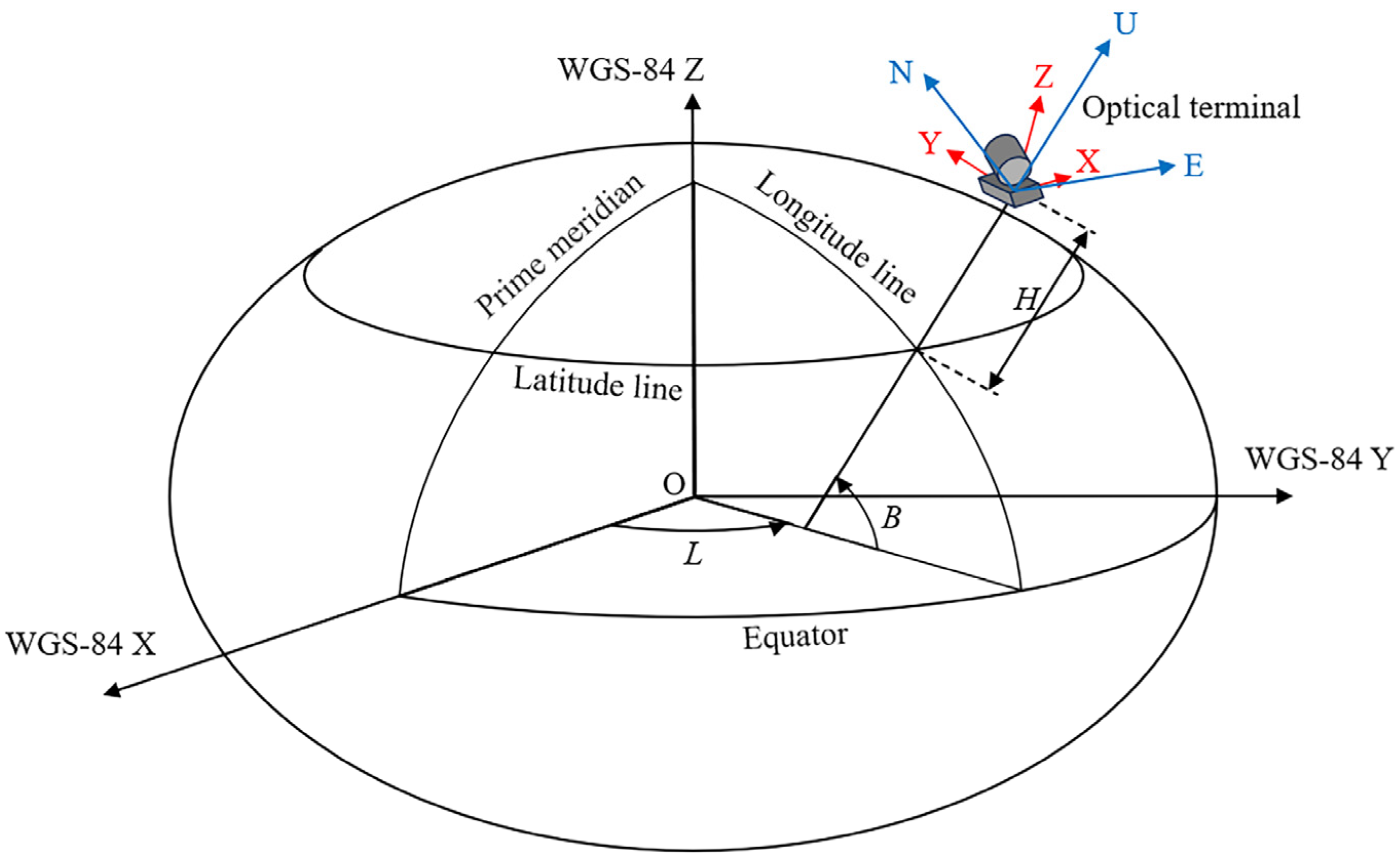
In laser communication systems, the initial alignment between two optical terminals is a prerequisite for establishing a functional link. The core of this alignment process lies in a hierarchical sequence of coordinate transformations. First, geodetic coordinates (longitude, latitude, and altitude) are acquired directly from GNSS measurements. These coordinates are then converted into the World Geodetic System 1984 (WGS-84) coordinate system, followed by sequential transformations into the East–North–Up (ENU) local coordinate system and the terminal-specific carrier coordinate system. Ultimately, the elevation and azimuth angles of the optical terminal are derived to ensure mutual alignment between the two terminals, thereby achieving initial pointing [
14]. The hierarchical relationships between these coordinate systems are schematically illustrated in
Figure 1.
2.1. Transformation from Geodetic to WGS-84 Coordinate System
Geodetic coordinates—comprising longitude (L), latitude (B), and altitude (H)—are directly acquired from GNSS measurements. The WGS-84 coordinate system is a geocentric reference framework. Its origin coincides with the Earth’s center of mass. The Z-axis points in the Conventional Terrestrial Pole (CTP) direction established by the Bureau International de l’Heure (BIH) 1984.0. The X-axis crosses the intersection of the BIH 1984.0-defined prime meridian (0° longitude) and the CTP equatorial plane. The X-, Y-, and Z-axes form a right-handed orthogonal coordinate system, adhering to the mathematical convention where the cross product of the Z-axis and X-axis generates the Y-axis direction [
15].
The transformation between geodetic coordinates (
L,
B,
H) and WGS-84 Cartesian coordinates (
x,
y,
z) is governed by
where
a denotes the semi-major axis of the Earth’s reference ellipsoid (
), and
represents the square of the first eccentricity (
).
2.2. Coordinate Transformation from WGS-84 Coordinate System to ENU Coordinate System
The ENU coordinate system is a local reference framework centered at a specific observation station or measurement point. Its origin corresponds precisely to the station’s geodetic position. In this system, the Z-axis (designated as the U-axis) aligns with the ellipsoidal normal direction of the origin position, extending vertically upward from the origin. The X-axis (E-axis) points to the east, and the Y-axis (N-axis) points to the true north. The E-, N-, and U-axes form a right-handed orthogonal coordinate system, adhering to the mathematical convention where the cross product of the N-axis and U-axis generates the E-axis direction.
Let
and
denote the WGS-84 coordinates of the target and optical terminal, respectively. The pointing vector in the WGS-84 coordinate system is expressed as
The corresponding representation in the ENU coordinate system is derived through the following transformation:
where
A is the attitude matrix defining the orientation of the ENU coordinates system relative to the WGS-84 coordinate system ((
L,
B,
H) belongs to
). This matrix is constructed as
2.3. Coordinate Transformation from ENU Coordinate System to Carrier Coordinate System
The carrier coordinate system is rigidly attached to the moving platform and dynamically adjusts with its motion. When optical terminals are mounted on non-stationary carriers or cannot be horizontally installed, coordinate transformation is essential to express the pointing vector in the carrier coordinate system, ensuring accurate steering of the turntable. The transformation relationship is defined as
where
M denotes the installation matrix (attitude matrix of the carrier coordinate system relative to the ENU coordinate system). The carrier coordinate system is derived through sequential Euler rotations from the ENU coordinate system: First, rotation about the Z-axis (U-axis). Second, rotation about the new Y-axis (N-axis). Third, rotation about the new X-axis (E-axis). This yields the following composite rotation matrix [
16]:
For the rotation matrix
M, there is
2.4. Elevation Angle and Azimuth Angle
The elevation angle θ of the optical terminal is defined as the angle between the optical axis and the XY-plane of the carrier coordinate system, with positive values assigned when the axis tilts toward the positive Z-direction, . The azimuth angle ϕ is defined as the angle between the projection of the optical axis onto the XY-plane and the Y-axis of the carrier coordinate system, measured clockwise from the Y-axis, . It should be noted that the elevation angle and azimuth angle here are both the rotation angles of the turntable and have no direct relationship with the Euler angle of the carrier.
To align the optical axis with the desired pointing vector, the turntable must rotate by the calculated azimuth angle
ϕ and elevation angle
θ. These angles are derived from the pointing vector
in the carrier coordinate system as follows:
3. Orientation Principle of GNSS Dual-Antenna System
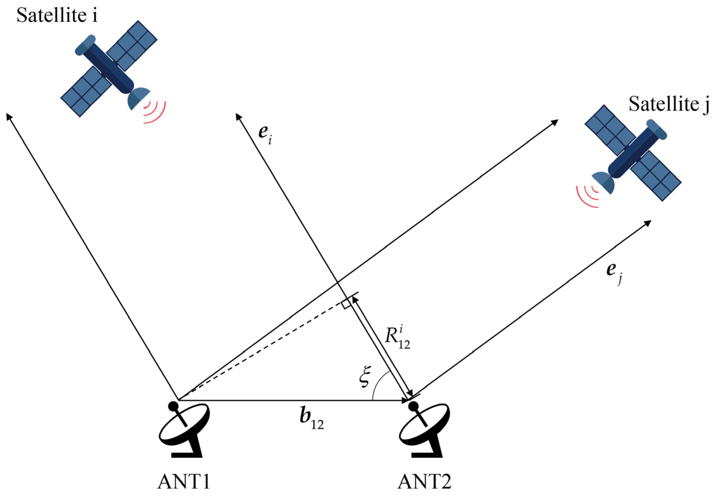
The GNSS dual-antenna positioning technology calculates the spatial position and orientation of a carrier by measuring the phase differences in GNSS signals received from navigation satellites. In the experiment, the GNSS dual-antenna system measures the angle between the baseline parallel to the carrier and the true north direction to calibrate the azimuth zero position of the turntable. Two GNSS receiver antennas are placed at both ends of the baseline, and simultaneous measurements of the same set of satellites are performed. Through differential processing, the baseline vector connecting the two GNSS antennas is determined. In engineering applications, the baseline length (typically on the meter scale) is far smaller than the distance between the antennas and navigation satellites. Thus, it is assumed that the vectors from satellite i to the master antenna (ANT1) and slave antenna (ANT2) are parallel, as illustrated in
Figure 2.
The difference in distance from satellite i to ANT1 and ANT2, denoted as
, can be interpreted as the projection of the baseline vector
onto the unit vector
pointing from ANT2 to satellite i. This relationship is expressed as
Due to the limited stability of internal quartz crystal oscillators in GNSS receivers, the clock bias between two receivers is challenging to directly resolve. To enhance precision and mitigate clock bias, a double-difference model is adopted by combining two single-difference measurements between stations and satellites. When ANT1 and ANT2 receive signals from the satellites i and j simultaneously, the double-difference carrier phase observable
is formulated as
where
is the wavelength,
represents the integer ambiguity of the carrier phase observation of satellite p by the receiving antenna i, and
denotes residual noise. By employing the double-difference model, receiver clock biases are eliminated, positioning errors are reduced, and multipath effects are suppressed. When substituting Equations (11) and (12), the double-difference observable
is rewritten as
By resolving the integer ambiguity
, the baseline vector bb in the WGS-84 coordinate system can be derived [
17]. Subsequently, the baseline vector is transformed into other coordinate systems using the methodologies outlined in
Section 2. By employing the double-difference model, clock biases between receivers are eliminated, positioning errors are reduced, and the impacts of multipath effects are suppressed. This model combines single-difference measurements from different antennas and satellite signals, ensuring that the observables retain only random observation noise and carrier phase errors induced by multipath effects. These residual errors exhibit favorable statistical properties and can be modeled and mitigated through various error compensation techniques, thereby achieving a high-precision orientation and positioning.
4. Error Analysis and System Installation
4.1. Theoretical Error Analysis and Experimental Error Calculation
After the calibration of the ground optical system, there are still systematic errors, mainly including platform attitude error (), positioning error (), and turntable execution error ().
The platform attitude error originates from incomplete parallelism between the carrier coordinate system and the ENU coordinate system during installation. This misalignment induces discrepancies between the theoretical and actual optical axis orientations when calculated pitch and azimuth angles are applied. The platform attitude error is formulated as
where
and
denote the errors of the pitch angle and the roll angle, and
is the error of the azimuth angle.
The positioning error arises from GNSS inaccuracies. This error is determined by the GNSS positioning accuracy and the communication distance between optical terminals. The positioning error is formulated as
where
,
, and
denote the positioning errors of GNSS in terms of longitude, latitude, and elevation, respectively.
represents the communication distance between two optical terminals. The units of
,
,
, and
are all meters (m). Given that
and
are the distance quantities on the surface of the Earth while
is an altitude quantity, for GNSS, the values of
and
are generally equal, and both are smaller than
.
The turntable execution error is the error caused by the rotation angle of the turntable when executing the rotation instruction is not precise enough. The turntable execution error is formulated as
where
and
denote the rotational errors of the azimuth axis and the elevation axis.
The accuracy of the digital inclinometer used in this test is 0.05°, so it is considered that the errors of the pitch angle and the roll angle caused by installation after leveling are . When the baseline length of the GNSS dual-antenna system used in the experiment is greater than 1 m, the pointing accuracy is 0.2°, so it is considered that the systematic error of the azimuth angle is . After calculation, it is obtained that the platform attitude angle error . According to the GNSS module specifications, the horizontal single-point positioning accuracy is 1.5 m and the vertical single-point positioning accuracy is 2.5 m. This means that and . The communication distance between two optical terminals . After calculation, it is obtained that the positioning error . The error of the two rotating axes of the turntable is , and the turntable execution error .
In conclusion, the initial pointing error of the optical terminal is
4.2. Horizontal Plane Calibration
For ground station optical terminals, achieving precise alignment between the carrier coordinate system and the ENU coordinate system is essential to simplify the installation matrix to an identity matrix, thereby minimizing computational complexity and systematic errors. In order to realize the alignment of the carrier coordinate system and the ENU coordinate system, the installation surface of the optical terminal must be strictly parallel to the EN-plane (East–North plane) of the ENU coordinate system. A digital inclinometer is utilized to adjust the attitude of the mounting platform until a horizontal state is achieved, ensuring parallelism between the XY-plane of the carrier coordinate system and the EN-plane of the ENU framework.
Define the horizontal plane as the zero reference for the elevation angle (
), with the upward orientation designated as positive. Let
denote the target elevation angle, and
represent the elevation angle correction value (initially set to 0; experimental values will be provided in
Section 6). The theoretical elevation angle input to the turntable is calculated as
4.3. True North Direction Calibration
After ensuring horizontal installation of the ground station optical terminal, the true north direction must be calibrated to align the azimuth angle zero reference of the terminal with the N-axis of the ENU coordinate system. This defines the azimuth angle as the angle between the projection of the optical axis onto the EN-plane and the N-axis, measured clockwise from true north. The calibration procedure employs a GNSS dual-antenna system to measure the baseline azimuth angle on the pre-calibrated horizontal plane, thereby determining the optical terminal’s azimuth zero reference. Assume that the operation mode of the turntable is as follows: The turntable rotates based on user-input azimuth () and elevation () angles relative to its factory-preset zero position. True north serves as the azimuth angle zero reference. When viewed along the negative U-axis (top-down perspective), anticlockwise rotation is defined as positive.
Let
denote the target azimuth angle, and
represent the baseline azimuth angle measured by the GNSS dual-antenna system. The deviation angle (
) between the baseline (initial side) and the turntable zero position (terminal side) is obtained from the installation. The theoretical azimuth angle input to the turntable is then given by
where
is the azimuth correction value (initialized to 0; experimental values are detailed in
Section 6). The fully calibrated system configuration is illustrated in
Figure 3.
5. Iterative Stellar Calibration Method
After the turntable rotates to the theoretical angles, the optical terminal typically cannot achieve direct alignment. A scanning process within a specific range along the target direction is required until the beacon light from one terminal is captured by the field of view (FOV) of the other terminal, thereby achieving initial alignment. This scanning range is termed the uncertainty region, defined as the set of pointing directions where the optical axis deviates from its theoretical position by a certain angle in any direction after the turntable completes its rotation based on the theoretical pointing. The pointing direction where the beacon light is captured has a high probability of belonging to this set. The radius of the theoretical uncertainty region, i.e., the maximum angular deviation of the pointing directions within this set, is expressed as
From Equation (17), the uncertainty region size caused by systematic errors is calculated as
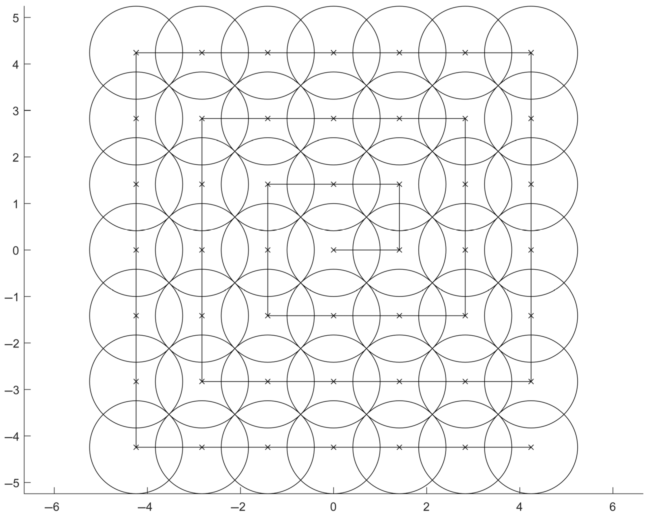
. Scanning methods for optical terminals, such as spiral scans and raster scans, inherently utilize the beacon light’s narrow divergence angle to cover all positions within the uncertainty region, thereby identifying the pointing direction where the beacon light can be captured. The differences among scanning methods lie in the ease of turntable trajectory implementation and whether the scan progresses from high-probability to low-probability regions to save time. The beacon light divergence angle in optical communication is typically small; in this experiment, the divergence angle is 800 μrad (0.046°). Taking the rectangular spiral scan illustrated in
Figure 4 as an example, to ensure full coverage of the scanning range, the step size should be less than or equal to
times the divergence angle. When the uncertainty region spans 1.26°, performing a rectangular spiral scan over this region requires over 1500 steps. Assuming a dwell time of 1 s per step to determine whether the beacon light is captured, the total scanning duration would reach 25 min. In practical scenarios, environmental factors may further enlarge the uncertainty region, leading to even longer scanning times. Under dynamic conditions, long-term scanning will cause the optical terminal to have a significant relative movement with the carrier, resulting in continuous degradation of the theoretical pointing accuracy, expansion of the uncertainty region, and ultimately, failure to establish a link.
To address the loss of theoretical pointing accuracy caused by an excessive scanning time during initial alignment, this study proposes an iterative stellar calibration method based on the experimental optical terminal. This method utilizes the FOV to capture visible stars and corrects the turntable’s pointing errors by referencing stellar positions from ephemeris data, thereby reducing the uncertainty region, shortening the scanning time, and enabling rapid link establishment. The workflow is illustrated in
Figure 5.
5.1. Iterative Stellar Calibration Procedure
The iterative stellar calibration procedure consists of several sequential phases to refine pointing accuracy. First, the ephemeris is queried to retrieve the target star’s azimuth () and elevation () angles at a predefined observation time relative to the ENU coordinate. Using Equations (18) and (19), the theoretical turntable orientation (, ) is computed and executed to align the optical axis with the predicted stellar position. Under the ground-fixed reference frame, stellar motion is modeled as an apparent rotation around Polaris: Polaris remains quasi-static within the narrow FOV, while non-polar stars traverse the FOV at angular velocities correlated to their declination. At the predefined observation time, if the star is detected, the turntable’s azimuth and elevation angles are fine-tuned to center the star in the FOV or ensure its trajectory crosses the FOV center. If undetected, a spiral search pattern is initiated around the target coordinates; failure to acquire the star within 2 min triggers ephemeris reselection and process repetition.
During error correction, turntable telemetry data is analyzed to identify the timestamp when the star traverses the FOV centroid, recording the corresponding input angles (
,
). Theoretical angles (
,
) at that instant are recalculated using Equations (18) and (19). Here, it can be known that the calculation formulas of (
,
) and (
,
) are the same. The only difference lies in the time. The time of (
,
) is before the stellar calibration, while the time of (
,
) strictly corresponds to (
,
). Correction values are then updated iteratively via
where
and
are the correction values before the nth stellar calibration, and
and
denote pointing errors. The smaller the pointing errors, the smaller the uncertainty region of the initial direction. Replace the original correction values with the new correction values, and repeat the above process until the error between the theoretical value and the actual value meets the requirements.
5.2. System Simulation
The principle of stellar calibration can be summarized as shown in
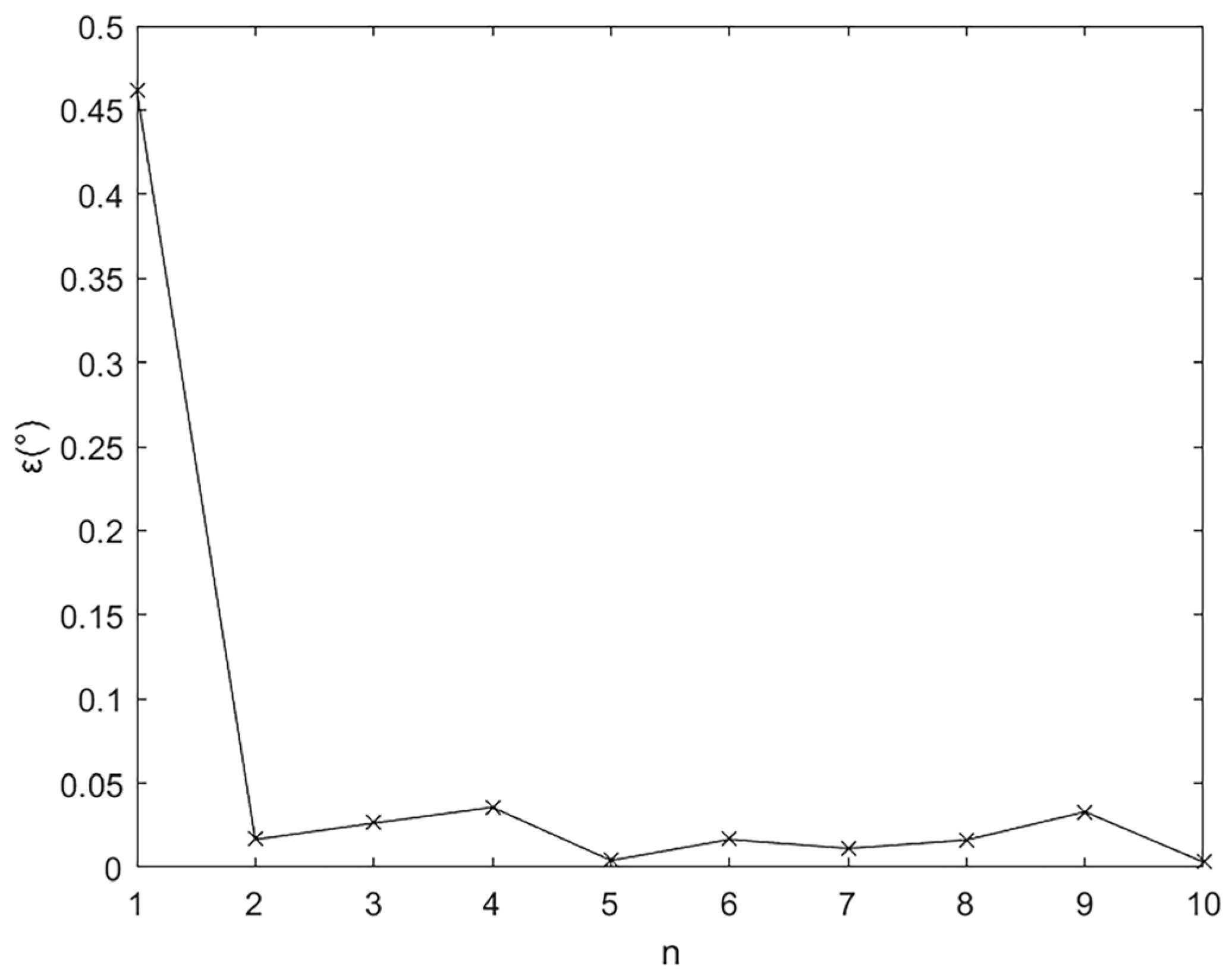
Figure 6. It is assumed that the actual pointing angle of the turntable’s first rotation follows a Gaussian distribution with a standard deviation of 0.21°. The deviation between the actual pointing and the theoretical pointing after the first rotation remains unchanged throughout the iterations. For subsequent rotations, the actual pointing angle of the turntable is assumed to follow a Gaussian distribution with a standard deviation of 0.00573°. Ignoring the errors of the high-precision ephemeris, during each observation, the star is guaranteed to appear within the FOV and as close as possible to the center of the FOV. Therefore, it is assumed that the angular position where the star is captured during stellar calibration follows a Gaussian distribution with a standard deviation of 1/6 of the FOV size (0.00764°). Assuming the errors follow a Gaussian distribution, the residual error after the n-th iteration is defined as
where
and
are the theoretical angles in the n-th iteration, and
and
are the measured values.
A simulation of the residual error generated by the stellar calibration process was conducted. The simulation results are shown in
Figure 7. It can be observed that after the first stellar calibration, the system’s residual error plummets rapidly. In subsequent calibration processes, the residual error is stably below 0.05°.
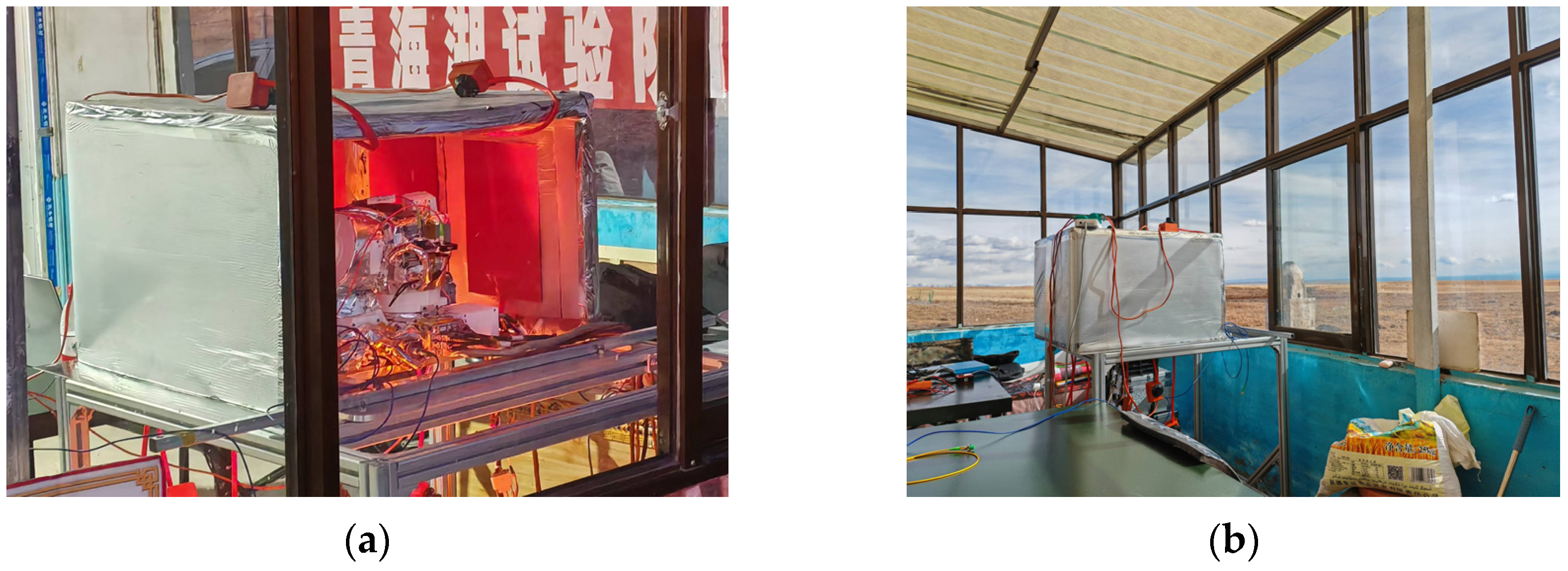
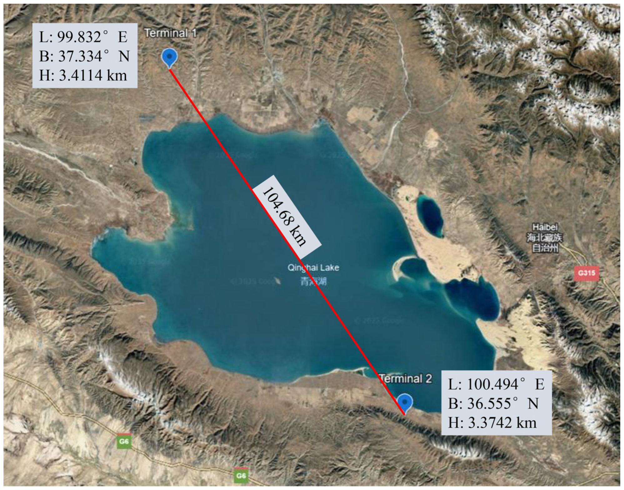
6. Experimental Validation
A field experiment was conducted at two sites separated by 104.68 km across Qinghai Lake, with their geographical coordinates listed in
Table 1. The appearances of Terminal 1 and the experimental environment are shown in
Figure 8, respectively. The relative positions of the two sites are illustrated in
Figure 9. In this experiment, the transmitting wavelength of Terminal 1 is 1540 nm, and the receiving wavelength is 1556 nm. The wavelength band of the coarse tracking camera is 800 nm, and that of the fine tracking camera is 1550 nm. The antenna aperture is 100 mm. For Terminal 2, the transmitting wavelength is 1550 nm, the receiving wavelength is 1540 nm, and the FOV of acquisition can reach 4°. The transmission rate is 100 Gbps. Terminal 1 transmits 800 μrad (0.046°) signal light for scanning, and Terminal 2 is the companion terminal responsible for staring and receiving.
In this experiment, the optical terminal at the ground station was mounted on a relay adapter plate, which was connected to a mounting platform with attitude adjustment capabilities. A digital inclinometer was used to precisely adjust the platform’s attitude until a horizontal state was achieved. Following horizontal alignment, a GNSS dual-antenna system was installed on an extension rod parallel to the pitch rotation axis of the relay adapter plate. The extension rod, approximately 1.2 m in length, was machined to ensure strict parallelism with the adapter plate, which meant that the deviation angle between the baseline and the turntable zero position was a right angle. The installation schematic is shown in
Figure 10. The deviation angle between the baseline and the turntable zero position was set to 90° or −90°, because during tooling production, the rectangular base plate of the optical terminal was designed to align with the GNSS extension rod, and at the same time, the zero position of the optical terminal was set parallel to the edge of the rectangular base plate of the optical terminal. The positive and negative are determined by the relative positions of the GNSS master and slave antennas. Even if this design may cause a certain error in the azimuth of the turntable, it can be corrected through stellar calibration.
The experimental configuration includes modeling ground stations and target stars [
18]. System timestamps were synchronized to query the azimuth and elevation angles of target stars at a specified observation time. To ensure reliable stellar detection under residual pointing errors, Polaris—a star with minimal positional variation in narrow FOV observations—is typically preferred. However, Terminal 1’s line-of-sight to Polaris was obstructed by buildings in this experiment. The experiment was conducted in November in the mid-latitudes of the Northern Hemisphere. The brightest stars in the southern sky at night were Fomalhaut (α PsA) and Diphda (β Cet). Fomalhaut, located in the constellation Piscis Austrinus, has a visual magnitude of +1.16 and is the 18th brightest star in the sky. Its declination is −29°37′20″, and at a latitude of 40° N, it reaches a maximum altitude of about 30° in the autumn night sky. Diphda, located in the constellation Cetus, is the brightest star in Cetus with a visual magnitude of +2.02. At the same observation point, its maximum altitude is approximately 35°. Given that the northern sky was obstructed, these two stars were selected for stellar calibration instead of Polaris due to their appropriate viewing angles and higher brightness compared to other observable stars during the experiment period.
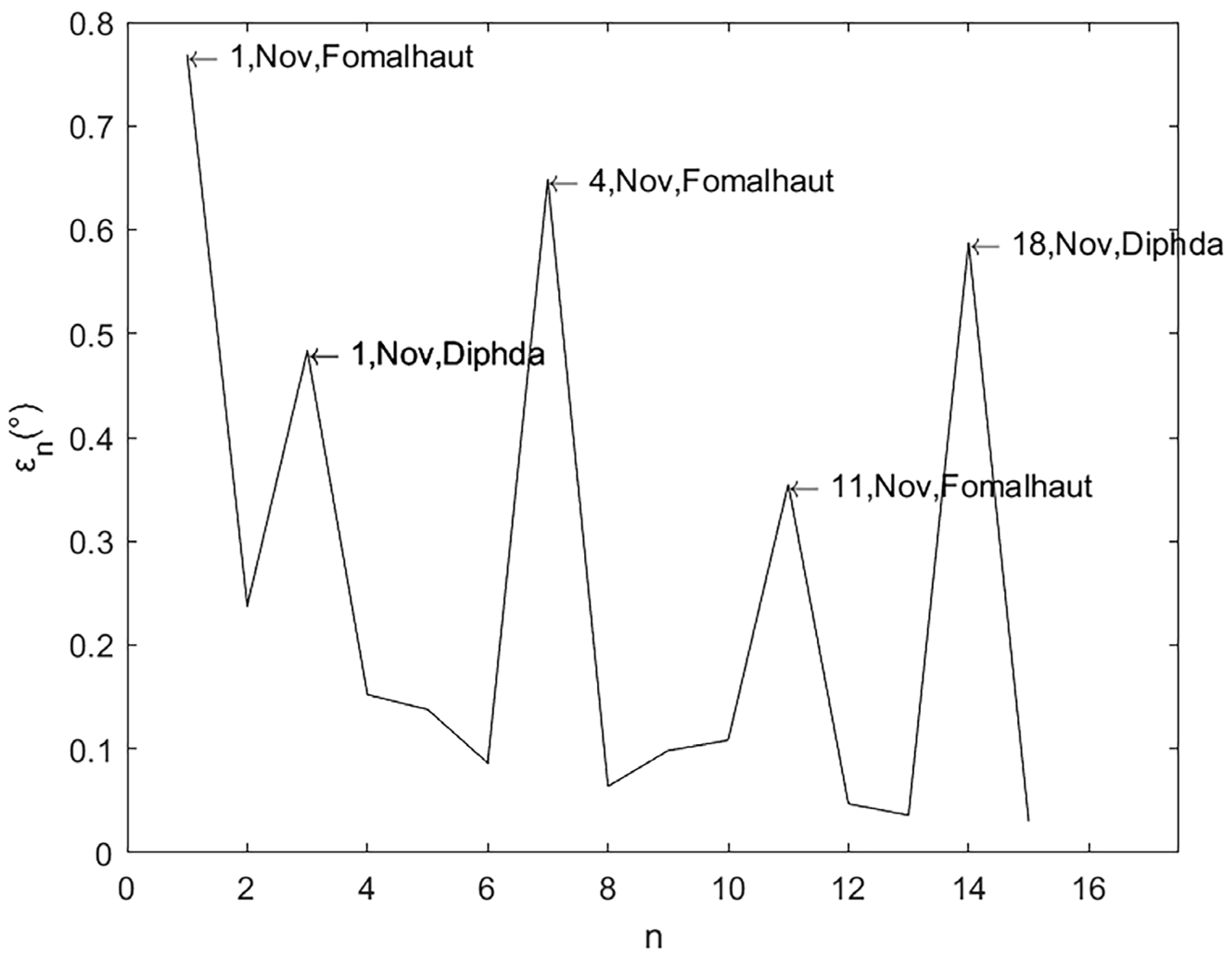
The experimental results are illustrated in
Table 2 and
Figure 11. Data points annotated with “Date, Month, Target Star” (e.g., “1, Nov, Fomalhaut” represents up to the next annotated point, obtained through successive iterations since the experimental time of November 1st, observing Fomalhaut) indicate instances where external disturbances (e.g., optical terminal is moved or reinstalled) occurred prior to the iteration. The HIP (Hipparcos Catalogue) is a star catalogue published by the European Space Agency using measurement data from the Hipparcos astrometric satellite. In
Table 2, “HIP” represents the star’s identifier in the Hipparcos Catalogue. The results demonstrate that, in the absence of such disturbances, the system achieves rapid residual reduction within 1–2 iterations. This satisfies the stringent requirements for high-precision laser communication link establishment.
When comparing the effects of the experimental results and the simulation results on the residual error, it was found that the experimental results were very close to the simulation results. The azimuth and elevation angle errors during link establishment between Terminal 1 and Terminal 2 were measured as −0.0293° and −0.0068°, respectively. Taking ±0.0293° as the boundary of the uncertainty region, the size of this uncertainty region is 0.0586°at this time. With a beacon beam divergence of 800 μrad (0.046°), this uncertainty region could be fully scanned and covered within a short timeframe, enabling rapid link establishment.
7. Conclusions
This study validates the feasibility and high-precision characteristics of optical terminal initial pointing technology through ground-based experiments. The proposed methodology integrates three key innovations: a multi-coordinate system transformation model that hierarchically maps geodetic coordinates to terminal-specific carrier coordinates, enabling accurate initial pointing calculations; a GNSS dual-antenna and digital inclinometer calibration system that reduces pointing errors through rigorous horizontal alignment and true north calibration; and an iterative stellar calibration technique that compresses the uncertainty region to 0.0586°, satisfying rapid link establishment requirements for narrow-beam laser communications. The experimental results over a 104.68 km terrestrial link demonstrate the superior performance compared to conventional methods, with azimuth and elevation errors reduced to −0.0293° and −0.0068°, respectively. The system exhibits exceptional robustness in complex geographical environments, maintaining a sub-milli-radian accuracy despite external disturbances.
8. Discussion
This study aims to provide high-precision initial pointing support for ground optical terminals in laser communication systems operating within complex environments. In laser communication experiments, the duration of the initial pointing scan is proportional to the area of the uncertainty region. When the beam divergence angle of the uncertainty region increases, the scan duration grows proportionally to the square of the divergence angle. Not only do excessively long scanning times impact link establishment efficiency but also, for moving carriers, a prolonged scanning can lead to positioning distortion. Consequently, excessively long scan times are unacceptable.
Previous research typically only addressed correcting initial pointing deviations by scanning the entire uncertainty region, seldom mentioning the issue of excessively long scan durations. Due to constraints imposed by the environment and deployment costs, ground-based laser communication terminals often cannot achieve zero-error assembly. When the resulting errors reach the degree level, scan times can escalate to the order of hours. To address that problem, this study attempts to correct systematic errors by referencing high-precision ephemerides.
The stellar calibration process occurs before initial pointing, acting as a pre-processing step for systematic errors. This ensures that when scanning begins towards the other optical terminal, the uncertainty region is sufficiently small to keep the scan duration within an acceptable range. The current research is still in the ground terminal experimental phase. In subsequent studies, the ground terminal will perform laser communication with a tethered balloon terminal in the same manner. The tethered balloon will carry a GNSS/INS system to perform real-time calibration of the optical terminal’s pointing, enabling a balloon-to-ground link. This will facilitate the investigation of the characteristics of long-distance, high-data-rate laser communication in dynamic environments.
Author Contributions
Conceptualization, X.W. and J.H.; methodology, Y.L. and X.W.; software, Y.L. and X.W.; validation, Y.L., X.W., and X.Q.; formal analysis, Y.L.; investigation, X.W.; resources, X.W.; data curation, Y.L.; writing—original draft preparation, Y.L.; writing—review and editing, Y.L. and X.W.; visualization, Y.L.; supervision, X.W. and J.H.; project administration, X.W.; funding acquisition, X.W. All authors have read and agreed to the published version of the manuscript.
Funding
This research was funded by the National Natural Science Foundation of China, grant number 62301558.
Institutional Review Board Statement
Not applicable.
Informed Consent Statement
Not applicable.
Data Availability Statement
The raw data supporting the conclusions of this article will be made available by the authors on request.
Conflicts of Interest
The authors declare no conflicts of interest.
Abbreviations
The following abbreviations are used in this manuscript:
| FSO | Free Space Optical Communication |
| GNSS | Global Navigation Satellite System |
| INS | Inertial Navigation System |
| WGS-84 | World Geodetic System 1984 |
| CTP | Conventional Terrestrial Pole |
| BIH | Bureau International de l’Heure |
| ENU | East–North–Up |
| FOV | Field of View |
| HIP | Hipparcos Catalogue No. |
References
- Wang, K.; Yu, J.; Bian, C.; Ding, J.; Zhang, J.; Zhu, M.; Yang, X.; Li, W.; Wei, Y.; Wang, M.; et al. Terahertz Transmitter Demonstration of the Simultaneous Transmission of Optical and Electrical Terahertz Band Signals at 1 Tb/s Bit Rate and 50 m Wireless Delivery. Sci. China Technol. Sci. 2025, 68, 384–386. [Google Scholar] [CrossRef]
- Song, X.; Wang, X.; Zhao, S.; Li, Y.; Li, X.; Zhang, X. Secure and Covert Communication Strategy of UAV Based on Hybrid RF/FSO System. Opt. Commun. 2025, 574, 131234. [Google Scholar] [CrossRef]
- Zhao, H.; Chen, C.; Ji, J. Experimental Investigation of UAV-Assisted FSO-CDMA System Over Turbulent Channel with Vibration Effects. Opt. Commun. 2025, 581, 131630. [Google Scholar] [CrossRef]
- Jain, V.; Reddy, B.V.R.; Payal, A. On the Performance of RIS-Assisted Energy Harvesting Over Mixed Dual-Hop RF-FSO Communications. Phys. Commun. 2025, 69, 102615. [Google Scholar]
- Mao, A.; Zhang, Y.; Bao, Z.; Li, X.; Lu, S.; An, Q. The Pointing Uncertainty Region’s Analysis of Inter-Satellite Laser Alignment Systems Under Multiple Uncertainties. Acta Astronaut. 2024, 220, 141–161. [Google Scholar] [CrossRef]
- Tsujimura, T.; Muta, S.; Masaki, Y.; Izumi, K. Initial Alignment Scheme and Tracking Control Technique of Free Space Optics Laser Beam. In Proceedings of the 2014 5th International Conference on Optical Communication Systems (OPTICS), Vienna, Austria, 28–30 August 2014; pp. 1–6. [Google Scholar]
- Hou, X.; Liu, Z.; Chang, Y.; Lu, S.; Fang, F.; Li, J. Analysis on Development Status and Trend of Space Laser Communication Technology. Chin. J. Lasers 2024, 51, 231–244. [Google Scholar]
- Bajaj, P.; Kataria, A.; Puri, V.; Gupta, V.; Min, H. OpticalTrust: A Sensor-to-Blockchain Framework Using Free-Space Optical Communication. Sensors 2024, 24, 7797. [Google Scholar] [CrossRef] [PubMed]
- Huang, Z.; Wang, Z.; Huang, M.; Li, W.; Lin, T.; He, P. Hybrid Optical Wireless Network for Future SAGO-Integrated Communication Based on FSO/VLC Heterogeneous Interconnection. IEEE Photonics J. 2017, 9, 7202310. [Google Scholar] [CrossRef]
- Sun, N.; Wang, Y.; Wu, Y.; Liu, J. High-Precision Tracking of Free-Space Optical Communication System on Mobile Platforms. Photonics 2024, 11, 900. [Google Scholar] [CrossRef]
- Wu, J.; Liu, C.; Zhang, L.; Tan, Y.; Zhou, C.; Song, Z.; He, Z.; Shu, R.; Wang, J.; Li, A. Realization of Beam Divergence Angle of Approximating Diffraction Limit for Satellite-Based Miniaturized Terminals. Opt. Laser Technol. 2025, 183, 112317. [Google Scholar] [CrossRef]
- Hu, H.; Liu, L.; Li, C.; Cao, G. Research on Composite Scanning Strategy for High-Probability Acquisition of Deep Space Cooperative Targets. Chin. Space Sci. Technol. 2022, 42, 58–66. [Google Scholar]
- Chai, D.; Song, S.; Wang, K.; Ning, Y.; Han, D. The Robust Pose Estimation of Single-Frequency Dual-Antenna GNSS RTK/MEMS INS Integration for Vehicle-Borne System. Navig. Position. Timing 2025, 12, 1–16. [Google Scholar]
- Peng, Z.; Guo, Y.; Zhu, H. Geolocation of a Known Altitude Target Using Azimuth Measurements Based on the Ellipsoidal Expansion in Normal Direction of WGS-84 Mode. In Proceedings of the 2023 35th Chinese Control and Decision Conference (CCDC), Yichang, China, 20 May 2023; pp. 427–432. [Google Scholar]
- Wu, Y.; Bai, Z.; Zhao, J.; Li, B.; Liu, Y. Technology and Application of Online Maps in Seismic Acquisition Design. In Proceedings of the SPG/SEG Nanjing 2020 International Geophysical Conference, Nanjing, China, 14–15 September 2025; pp. 148–151. [Google Scholar]
- Miao, W. Research on Attitude Calculation and Control Algorithms for Rotor UAVs. Master’s Thesis, North University of China, Taiyuan, China, 2024. [Google Scholar]
- Qian, X. Research on Integrated Navigation System Based on Dual Antenna GNSS and INS. Master’s Thesis, Beijing Forestry University, Beijing, China, 2023. [Google Scholar]
- Gou, J. Design and Implementation of Satellite Orbit and Communication Link Simulation System Based on STK. Master’s Thesis, Xidian University, Xi’an, China, 2023. [Google Scholar]
| Disclaimer/Publisher’s Note: The statements, opinions and data contained in all publications are solely those of the individual author(s) and contributor(s) and not of MDPI and/or the editor(s). MDPI and/or the editor(s) disclaim responsibility for any injury to people or property resulting from any ideas, methods, instructions or products referred to in the content. |
© 2025 by the authors. Licensee MDPI, Basel, Switzerland. This article is an open access article distributed under the terms and conditions of the Creative Commons Attribution (CC BY) license (https://creativecommons.org/licenses/by/4.0/).


