Abstract
To address the challenge of laser beam distortion induced by thermal effects in high-power slab laser amplifiers, a coupled thermal–mechanical–optical model for a face-pumped Yb:YAG multi-pass amplifier was developed. The thermal effects under different thermal management strategies were systematically investigated using the finite element method. Firstly, the temperature distribution, thermal stress, and deformation within the Yb:YAG crystal were analyzed and compared under both room-temperature (293 K) and cryogenic (150 K) cooling conditions using a microchannel cooling structure. The results demonstrate that under a pump power of 100 W and room-temperature cooling, the peak temperature of the gain medium reaches 363 K, with a peak thermal stress of 1.04 MPa and a maximum thermal deformation of 1.44 μm. In contrast, under cryogenic cooling at 150 K, the maximum temperature is reduced to 188 K, and both thermal stress and deformation exhibit a more uniform distribution within the pumped region. Subsequently, the thermal lensing of bonded and non-bonded Yb:YAG crystals was compared and analyzed by ray-tracing. It was found that under a pump power of 100 W, the thermal focal lengths of non-bonded Yb:YAG are 1112 mm and 2559 mm at cooling temperatures of 293 K and 150 K, respectively. For bonded crystals with a 3 mm undoped YAG thickness under identical pumping and cooling conditions, the corresponding thermal focal lengths measure 1508 mm and 3044 mm. When the undoped YAG thickness increases to 6 mm, the thermal focal lengths further extend to 1789 mm and 4206 mm, respectively.
1. Introduction
High-power solid-state lasers with high beam quality are crucial in various fields such as industrial processing, military defense, and scientific research. The Master Oscillator Power-Amplifier (MOPA) configuration is a common system architectures used to achieve high power laser output. However, scaling the output power inevitably leads to increased thermal load in the gain medium. Thus, effective thermal management is crucial for high-power lasers and amplifiers. Researchers have conducted extensive studies on the generation and dissipation of heat in laser systems, addressing aspects including pump uniformity, gradient doping of laser materials, as well as the design of heat sinks and transition layers [,].
Owing to its large aspect ratio and efficient face-cooling capability, the thin-slab laser architecture has found widespread application in high-power solid-state laser systems, such as the Mercury (United States), Halna (Europe), and Lucia (France) devices [,,]. Compared to rod-type geometries, the thin-slab design offers inherent advantages in thermal management [,]. However, under high-power pumping conditions, significant thermal distortion still persists within the laser medium. The presence of thermal distortion substantially affects the amplification efficiency, beam quality, and directionality of laser amplifiers, particularly in multi-pass amplification architectures where the impact of thermal distortion on the amplified beam deteriorates cumulatively [,,]. Consequently, active compensation techniques for thermal distortion are also widely employed in laser amplifiers [,,]. This paper establishes a model of a face-pumped, active-mirror Yb:YAG multi-pass amplifier and analyzes the temperature, stress, thermal lens, and surface deformation of the laser medium under high-power operation using the finite element method. The ray tracing method is employed to analyze the spatial distribution of the beam at different positions. Finally, a comparative analysis evaluates how a composite crystal design improves end-face thermal distortion.
2. Theoretical Model
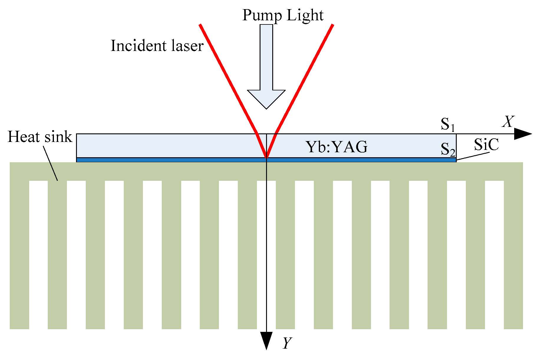
The structure of the face-pumped active-mirror thin-slab Yb:YAG amplifier is illustrated in Figure 1. The pump light enters the Yb:YAG crystal vertically through its front surface (S1), while the seed light for amplification is incident at a small angle. The S1 surface is coated with an anti-reflection (AR) coating for both the pump and seed beams, whereas the rear surface (S2) is coated with a high reflection (HR) coating for both wavelengths. The S2 surface also serves as a cooling interface. Microchannel structures are widely used for thermal management in high-power lasers [,]. Through the design of micro-scale channel configurations, the heat dissipation area can be significantly expanded, effectively enhancing the cooling efficiency and temperature field uniformity of the heat sink [,]. To ensure optimal thermal contact between the crystal and the cooling heat sink, silicon carbide (SiC) can be employed as an intermediate layer []. The internal thermal diffusion in face-pumped Yb:YAG can be described by the classical heat conduction equation,
where ρ is the density of the material, C is the specific heat capacity of the material, T is the temperature at different spatial locations at different times, k is the thermal conductivity of the material, q is the heat source, and the heat distribution of the pump light reflected from the S2 surface inside Yb:YAG can be expressed as,
where α is the absorption coefficient of the material, η is the heating coefficient caused by quantum defects, h is the thickness of the material, I0 is the power density of the pump laser, f (x, y, z) is the spatial distribution of the pump laser, y direction is the incident direction of the pump laser, g(t) is the time distribution of the pump laser.
Figure 1.
Schematic of the face-pumped active-mirror thin-slab Yb:YAG amplifier.
3. Design of Amplifier
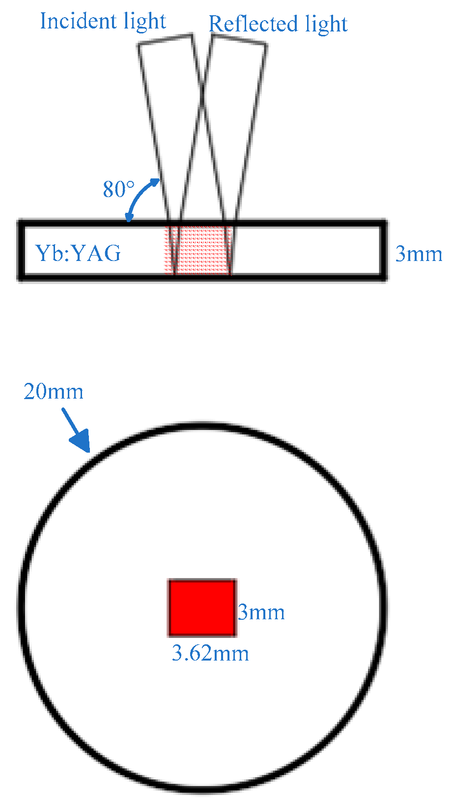
To enhance the amplification efficiency of the laser amplifier, the seed light and pump light should overlap as much as possible within the laser crystal. The Yb:YAG crystal exhibits a doping concentration of 3 at.%. Based on previous experimental data, the absorption coefficient for 940 nm pump light at this doping level is 4.35 cm−1. For a crystal thickness of 3 mm, approximately 92.65% of the pump light is absorbed after reflection at the S2 surface []. Therefore, the crystal thickness was designed to be 3 mm to maximize pump absorption. For optimal energy extraction, the seed light should largely overlap with the pump region to fully extract the available energy. When a seed light with a spot size of 3 mm × 3 mm is incident on the Yb:YAG crystal at an angle of 10°, it refracts at the S1 surface. Given the refractive index of Yb:YAG is 1.82, the refraction angle is calculated to be 5.47°. After reflection at the S2 surface, a pump light size of 3 mm × 3.62 mm sufficiently covers the entire path of the seed light throughout the crystal, as illustrated in Figure 2. Table 1 lists the material parameters of Yb:YAG used in the simulations. The thermal conductivity of Yb:YAG is highly temperature dependent, with a value of approximately 8.2 W/(m·K) at room temperature (293 K), increasing to 15.5 W/(m·K) at cryogenic temperature (150 K).
Figure 2.
The overlap between the pump light and the seed light inside the crystal.
Table 1.
The main parameters of Yb:YAG.
Table 2 shows the relevant laser parameters. The wavelengths of the pump and seed light are 940 nm and 1030 nm, respectively. Both beams exhibit a uniform flat-top intensity distribution. The heat generation rate in the Yb:YAG crystal, primarily resulting from the quantum defect, is approximately 10% of the absorbed pump power.
Table 2.
The main parameters of lasers.
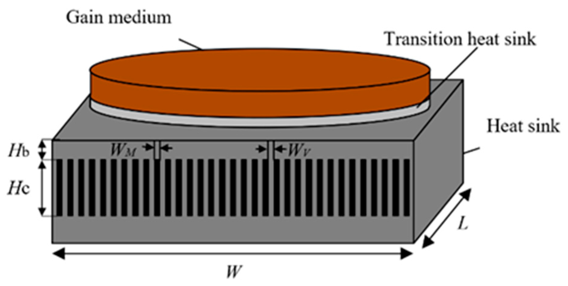
The cooling heat sink employs a microchannel structure made of oxygen-free copper with a thermal conductivity of 398 W/(m·K) []. The structure of the cooling heat sink is shown in Figure 3. The overall dimensions of the heat sink are 42 mm (L) × 42 mm (W). Each microchannel has a cross-sectional size of 4 mm in height (Hc) by 0.6 mm in width (Wm), with an interchannel spacing (Wv) of 0.6 mm. The channel roof maintains a 1 mm thickness (Hb) to the transition layer. The transition layer is made of single-crystal silicon carbide (SiC) with a thickness of 1 mm and a thermal conductivity of 490 W/(m·K).
Figure 3.
The finite element model of the gain medium and heat sink.
4. Results and Discussion
4.1. Temperature, Thermal Stress and End-Face Deformation
Figure 4 shows the temperature, stress, and end-face deformation within Yb:YAG under a pump power of 100 W. When the pump power is 100 W, approximately 10 W of heat is generated. The cooling heat sink employs forced water cooling with a convective heat transfer coefficient of 15,000 W/(m2·K), while the remaining surfaces are subjected to air convection cooling. The temperature of both the cooling water and the air is set to 293 K. It can be observed that the maximum temperature inside the crystal occurs at the center of the pump end face, with a value of 363 K, while the minimum temperature is located on the cooled surface of the crystal, with a value of 293 K, equal to the temperature of the cooling water, as shown in Figure 4a. The temperature gradient inside the crystal leads to the generation of thermal stress. With the plane where the crystal contacts the transition layer fixed, the stress distribution of the crystal is shown in Figure 4b. The maximum thermal stress also occurs at the pump end face, with a value of 1.04 MPa. The presence of thermal stress causes significant thermal deformation at the end face, as shown in Figure 4c, where the maximum deformation is 1.44 μm.
Figure 4.
The distribution of temperature (a), thermal stress (b) and thermal deformation (c) of Yb:YAG with the pump power of 100 W and cooling temperature of 293 K.
At low temperatures, the thermal conductivity of Yb:YAG increases significantly, thereby enhancing heat dissipation. Liquid nitrogen cooling is employed in the microchannels, with the cooling temperature set at 150 K and a convective heat transfer coefficient of 15,000 W/(m2·K), while the other surfaces of the crystal are adiabatic. Under the same pumping conditions, the resulting temperature, thermal stress, and end-face deformation are shown in Figure 5. The maximum temperature also occurs at the center of the crystal end face, measuring 188 K. Compared with room-temperature cooling, the temperature gradient within the crystal is significantly reduced. However, under the same fixed constraints, the crystal experiences compressive stress due to the low-temperature environment. The maximum stress, as shown in Figure 5b, is 2.05 MPa, located at the edge of the contact surface between the gain crystal and the transitional heat sink. Meanwhile, the maximum thermal deformation occurs at the edge of the crystal’s front end face (S1), with a value of 2.05 μm, as illustrated in Figure 5c. In the pump region, which is more critical for seed light transmission, the maximum stress and end-face deformation are 1.22 MPa and 1.45 μm, respectively.
Figure 5.
The distribution of temperature (a), thermal stress (b) and thermal deformation (c) of Yb:YAG with the pump power of 100 W and cooling temperature of 150 K.
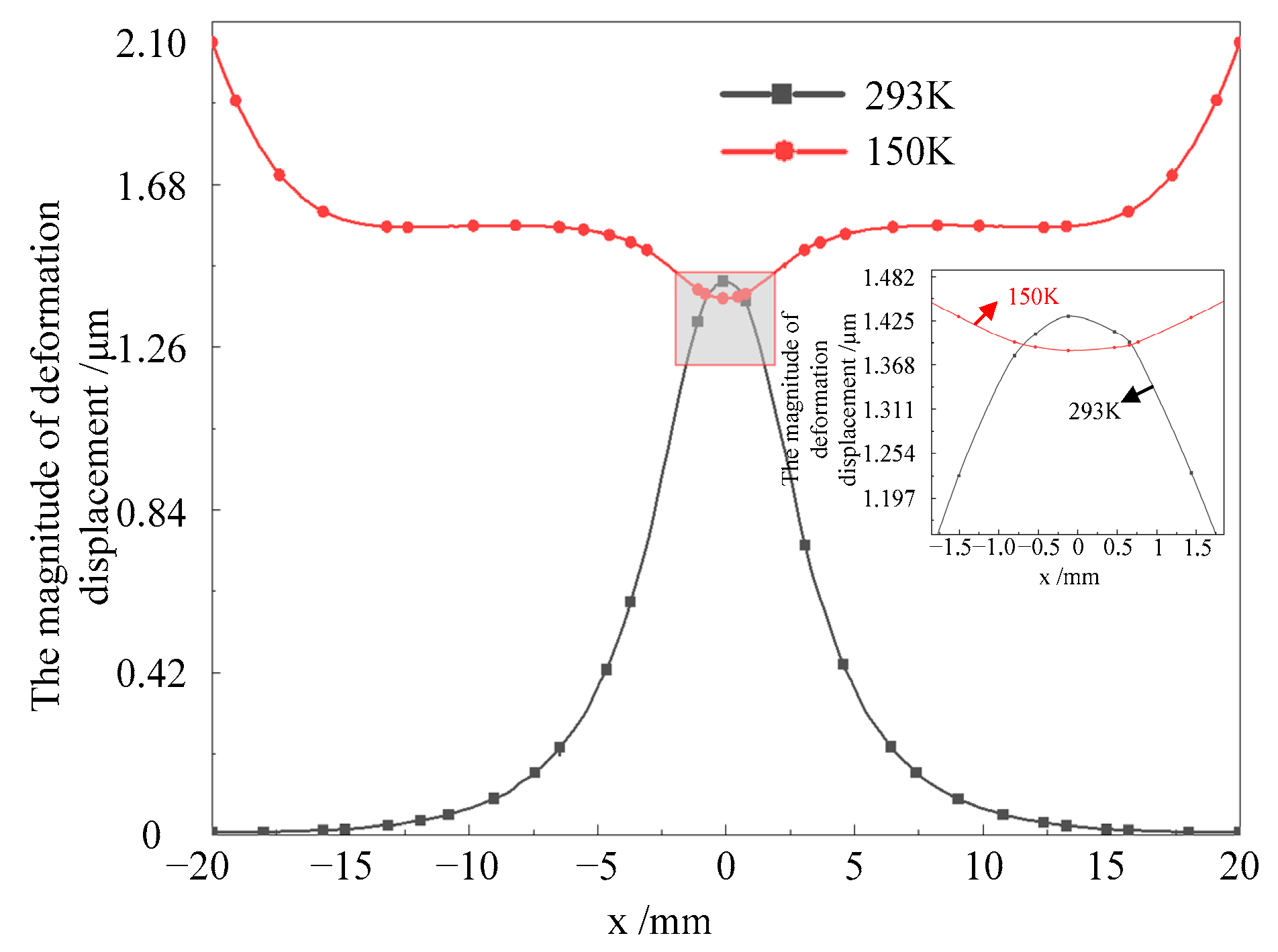
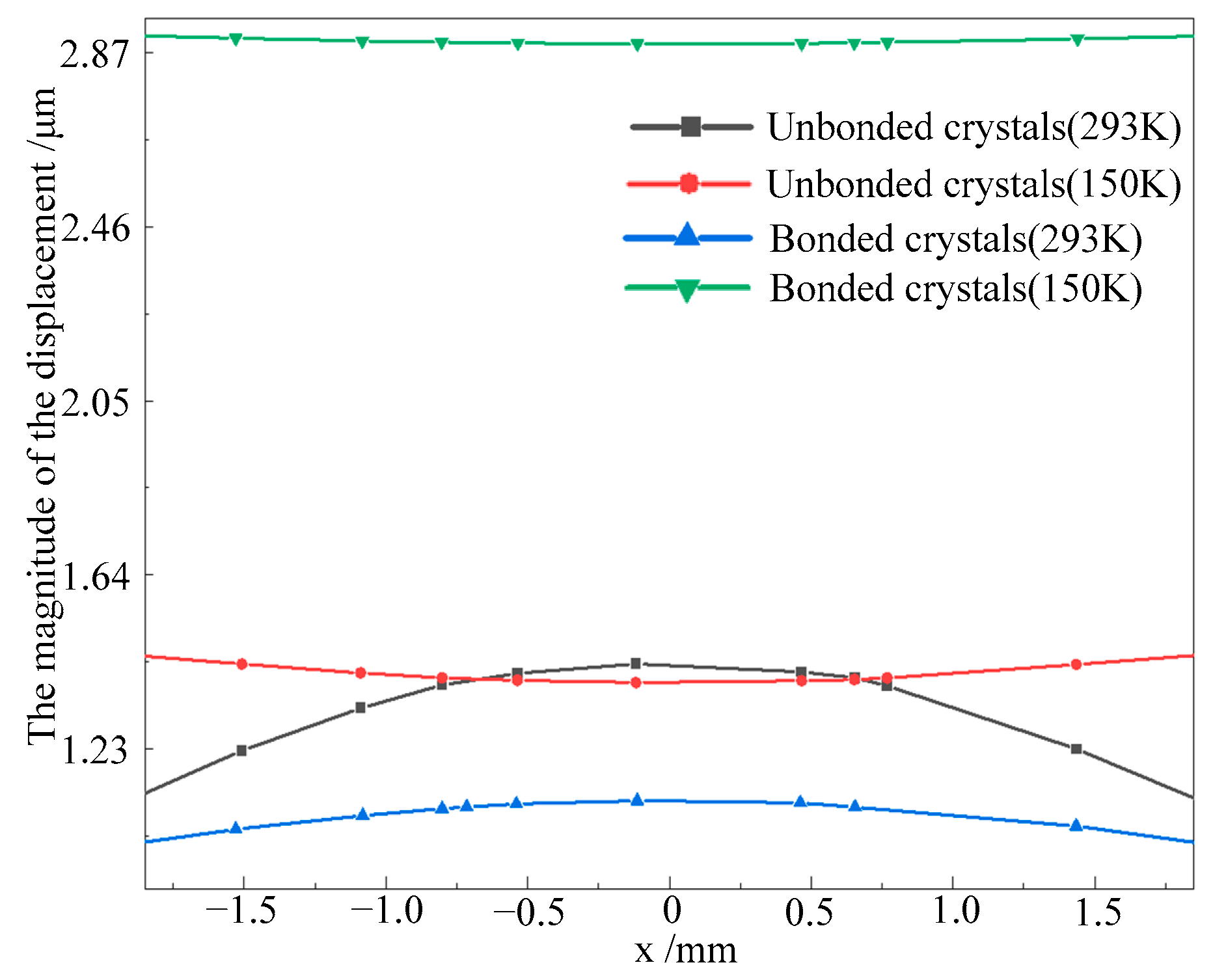
Figure 6 shows the magnitude of end-face deformation along the x-direction on surface S1. It can be observed that at room temperature, the maximum deformation occurs at the center of the surface. Under cryogenic conditions, however, the internal compressive stress causes the maximum deformation to appear at the edges of the surface, with its absolute value being greater than the deformation measured at the same location under room temperature conditions. Fortunately, the variation in end-face deformation under low temperatures is more gradual. In the pumping region, the difference between the maximum and minimum deformation is 0.3 μm at room temperature, whereas under low temperatures, this difference is reduced to 0.05 μm.
Figure 6.
End-face deformation of Yb:YAG under 100 W pump power.
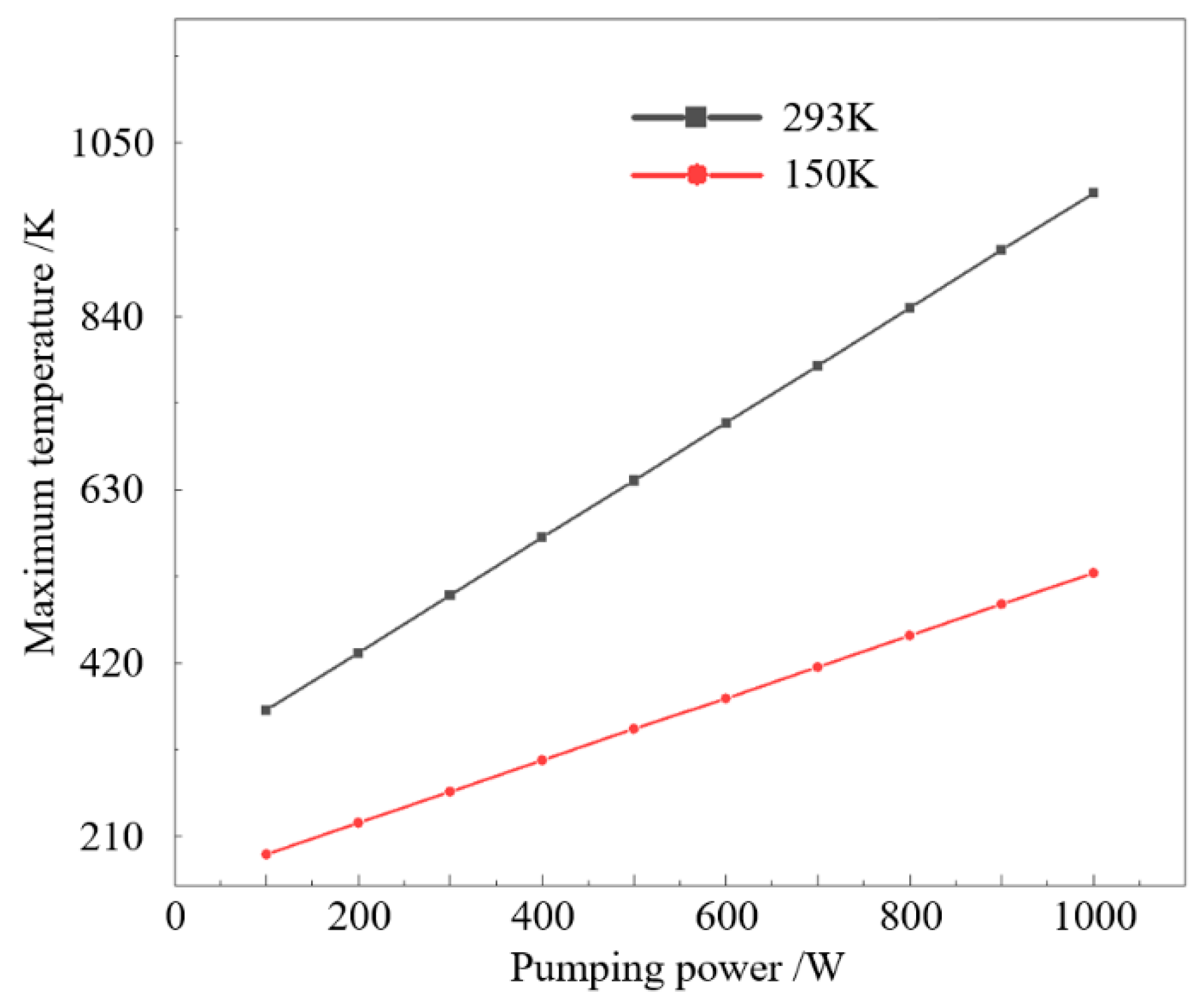
Figure 7 shows the maximum temperature inside the crystal under room and cryogenic temperature cooling at different pump powers. It can be observed that as the pump power increases, the improvement effect of cryogenic cooling on the temperature gradient becomes increasingly pronounced.
Figure 7.
The maximum internal temperatures of Yb:YAG crystals under different pump powers.
4.2. Thermal Lens
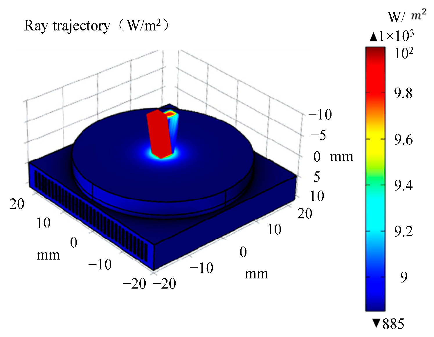
The presence of temperature gradients, thermal stress, and end-face deformation can lead to a thermal lensing effect when the seed laser propagates through the amplifier. This effect generates a thermal focal point during transmission, which not only reduces the amplifier’s efficiency but also poses risks to the safety of optical components. This study utilizes the geometric optics module of finite element software to simulate the spot size of the incident seed light at different positions using the ray tracing method. Figure 8 shows the ray tracing diagram of uniformly distributed seed light (3 × 3 mm) incident on the Yb:YAG crystal surface S1 at a 10° angle and subsequently reflected by surface S2. The red rays on the left represent the incident light, while the blue rays on the right correspond to the reflected light.
Figure 8.
The ray trajectory of seed light.
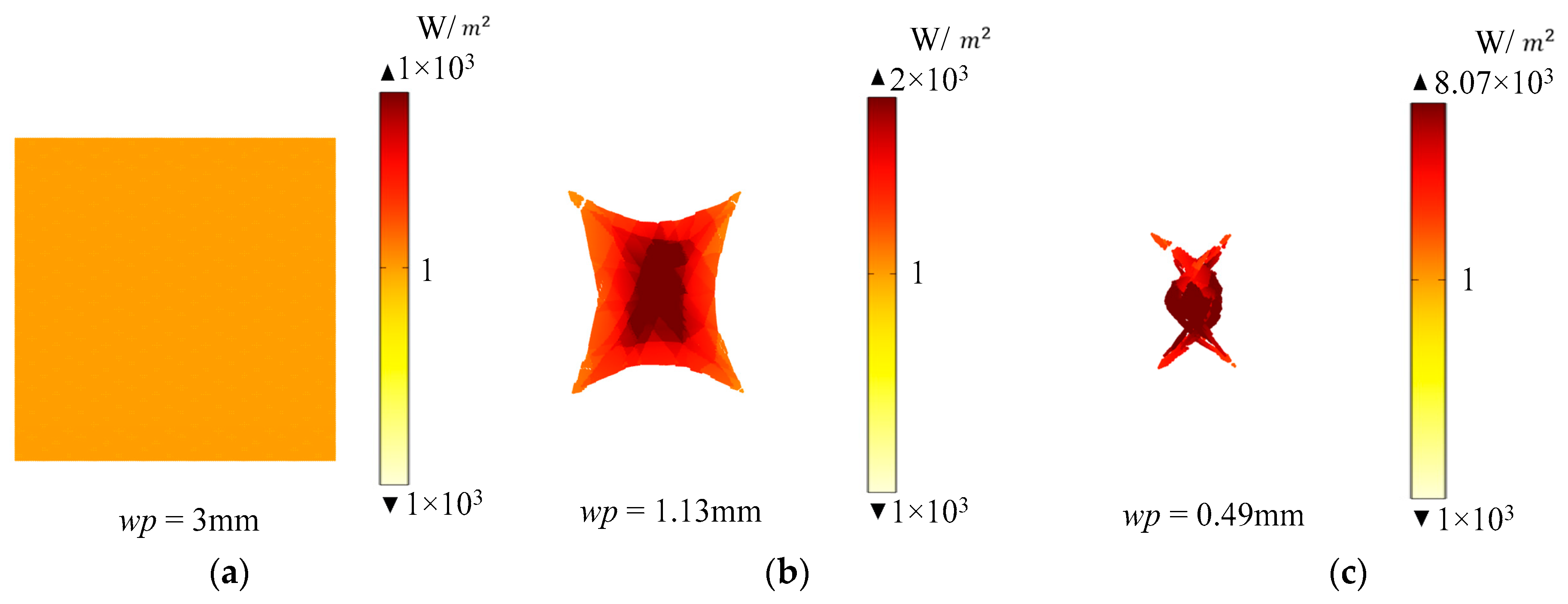
Based on the variation in the seed light spot size during propagation, the thermal lens focal length of the seed light under different pump powers can be determined. Figure 9 illustrates the spot shapes of the seed light at different propagation positions under a pump power of 100 W. Figure 9a shows the spot when the light just enters the S1 surface, with a spot size of 3 mm × 3 mm. Starting from this point, when the seed light propagates to a distance of 619 mm from the S1 surface, the spot shape is shown in Figure 9b. At this position, the spot is no longer a regular square, and the intensity at the center becomes increasingly higher. The spot size at its narrowest point is approximately 1.13 mm. When the seed light propagates to a distance of 1112 mm, the spot size reduces to about 0.49 mm. Beyond this distance, the spot size increases again. Therefore, it can be determined that the thermal focal length under a pump power of 100 W is approximately 1112 mm. The thermal focal length can also be approximately calculated using the following formula,
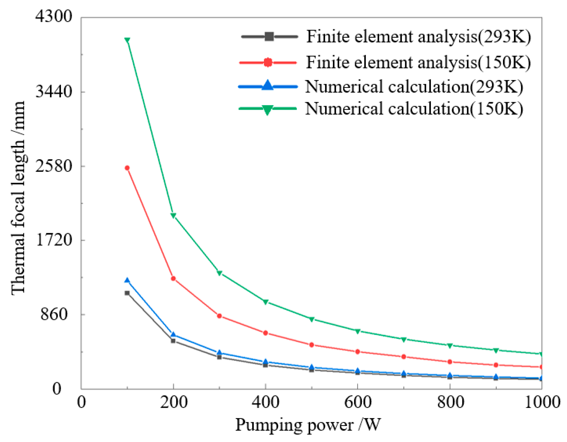
where k is the thermal conductivity of the gain crystal, A is the effective area of the pump light, Pin is the incident pump power, η is the thermal conversion efficiency, dn/dT is the thermal optical coefficient, α is the absorption coefficient of the crystal, and h is the thickness of the crystal. Figure 10 shows the variation in the thermal lens focal length obtained by two different methods with increasing pump power. It can be observed that the thermal lens focal lengths derived from both the finite element method and the numerical calculation method exhibit consistent trends. However, under the same pumping and cooling conditions, the thermal focal length obtained through numerical calculation is larger than that from finite element analysis. This discrepancy primarily arises because the numerical calculation mainly considers the thermal lensing effect caused by refractive index changes due to internal temperature gradients in the crystal, whereas the finite element method comprehensively accounts for the combined effects of both temperature gradients and end-face deformation.
Figure 9.
Seed light spots at different positions: (a) S1 surface, (b) at a distance of 619 mm from the S1 surface, (c) at a distance of 1112 mm from the S1 surface.
Figure 10.
The variation in the thermal focal length of Yb:YAG crystal with pump power.
4.3. Crystal Optimization
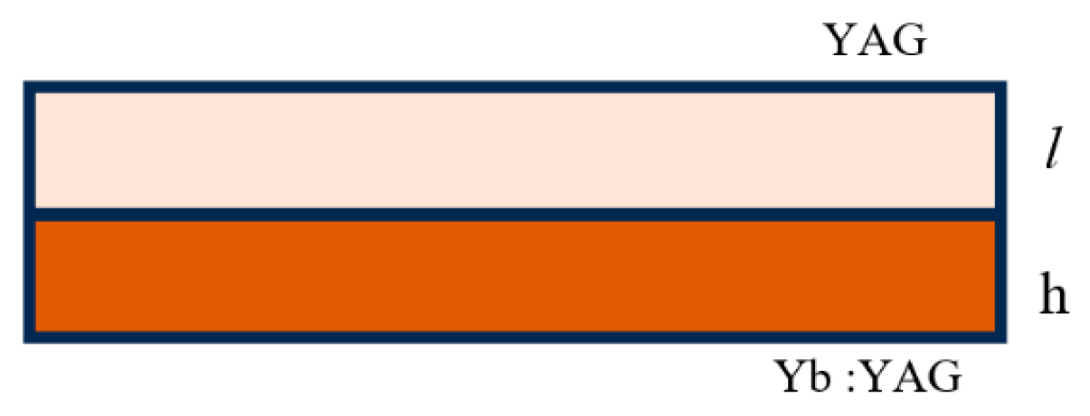
To mitigate the thermal load in Yb:YAG crystal under high-power pumping, an end-bonding technique was employed. An undoped YAG crystal of identical radius and a thickness of l = 3 mm was bonded to the pumped end-face of the Yb:YAG crystal, as illustrated in Figure 11.
Figure 11.
Schematic diagram of bonded Yb:YAG structure.
Figure 12 shows the temperature, stress, and end-face deformation of the composite crystal structure under room-temperature cooling at a pump power of 100 W. It can be observed that for the composite crystal, both the maximum temperature and stress occur at the bonding interface, measuring 340 K and 0.502 MPa, respectively. Compared to the unbonded crystal (363 K and 1.04 MPa), these values show a significant reduction. The end-face deformation also decreases from 1.44 μm to 1.11 μm.
Figure 12.
Internal temperature (a), thermal stress (b) and thermal deformation (c) distribution of a 3 mm undoped YAG thickness bonded Yb:YAG crystals under 100 W pump power and room temperature (293 K) cooling conditions.
Figure 13 shows the temperature, stress, and end-face deformation of the bonded crystal under 100 W pump power with low-temperature (150 K) cooling. The maximum temperature of the bonded crystal is located at the bonding interface, with a value of 175 K, as shown in Figure 13a. Under the same low-temperature cooling conditions, the locations of the maximum stress and end-face deformation coincide with those in the non-bonded crystal, with corresponding values of 3.27 MPa and 3.96 μm, respectively, as shown in Figure 13b,c. The variation in end-face deformation within the pump region directly influences the magnitude of the thermal lens focal length of the seed light. Figure 14 shows the end-face deformation within the pump region of both bonded and non-bonded crystals under room-temperature and low-temperature conditions. It can be observed that under room-temperature cooling, the end-face deformation of the crystal is lower at the edges and higher at the center, whereas under low-temperature conditions, the opposite trend is observed. As shown in Figure 14, the bonded structure Yb:YAG exhibits a difference between the maximum and minimum end-face deformation in the pumped region of 0.06 μm at room temperature and 0.01 μm under cryogenic cooling, respectively, while the corresponding values for unbonded Yb:YAG are 0.3 μm and 0.10 μm. So the bonded structure can effectively reduce the disparity in end-face deformation within the pump region under both room-temperature and low-temperature cooling conditions.
Figure 13.
Internal temperature (a), thermal stress (b) and thermal deformation (c) distribution of a 3 mm undoped YAG thickness bonded Yb:YAG crystals under 100 W pump power and low-temperature (150 K) cooling conditions.
Figure 14.
End-face deformation in the pump region of the Yb:YAG crystal.
Figure 15 shows the thermal focal length of the bonded crystal at different pump powers. Compared with the non-bonded crystal, the bonded crystal exhibits a significantly increased thermal focal length, indicating a mitigation of the thermal lens effect.
Figure 15.
Thermal focal length of a 3 mm undoped YAG thickness bonded Yb:YAG crystals under different pump powers.
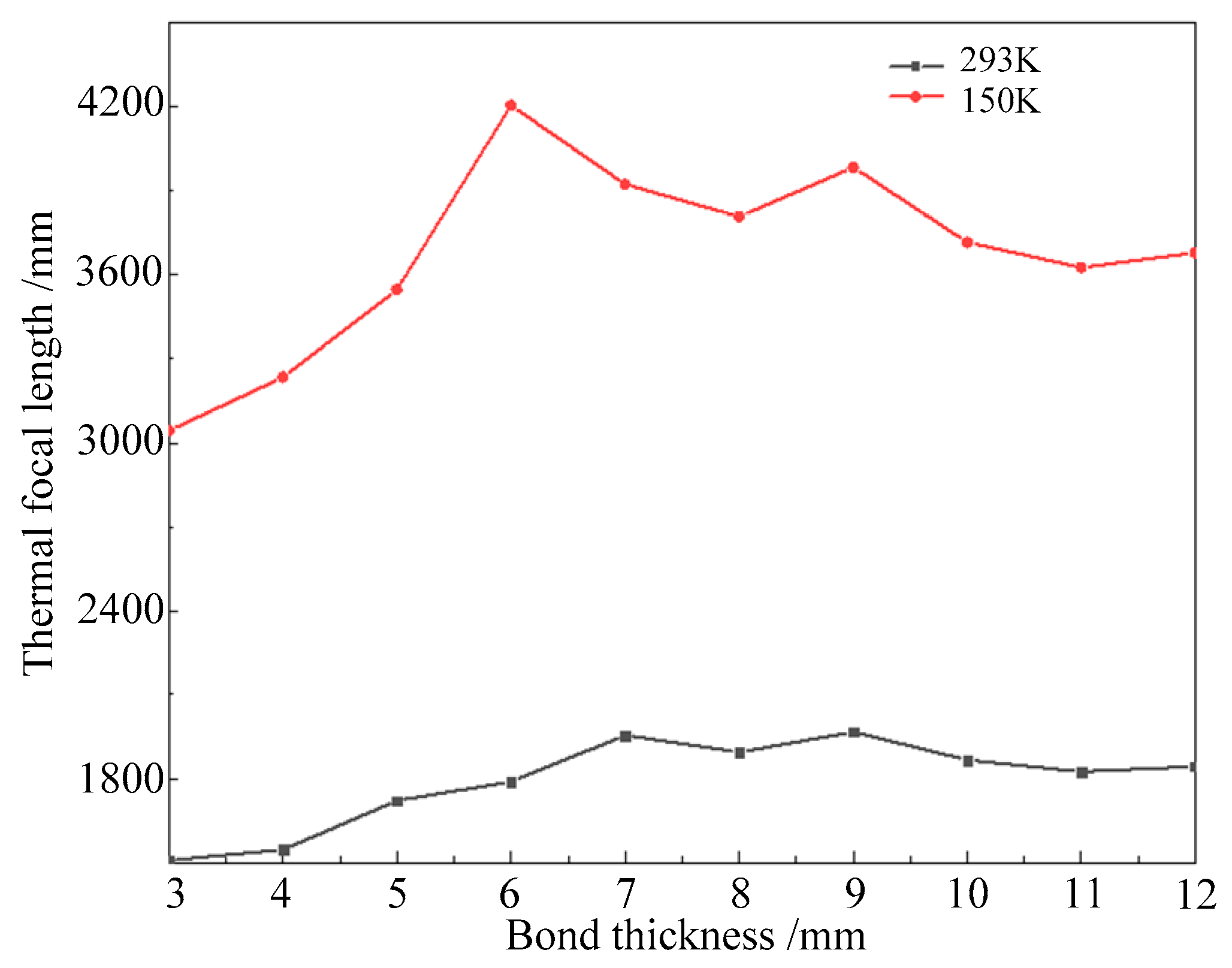
The thickness of the undoped YAG (l) in the bonded crystal also affects the thermal focal length. Figure 16 shows the thermal focal length under a 100 W pump power, obtained using the ray-tracing method, for different undoped YAG thicknesses. It can be observed that as the thickness of undoped YAG increases, the thermal focal length significantly increases under both room-temperature and low-temperature cooling conditions. However, when the thickness exceeds 6 mm, further increase in YAG thickness shows limited improvement in mitigating the thermal lens effect of the crystal.
Figure 16.
Thermal focal length of bonded crystals under 100 W pump power at different undoped YAG thicknesses.
5. Conclusions
The thermal effects induced by increasing power in solid-state lasers and amplifiers can severely degrade beam quality. Using a face-pumped Yb:YAG crystal as an example, this study investigates its temperature gradient, thermal stress, and end-face thermal deformation under various pump powers and cooling conditions. The ray-tracing method was employed to analyze the temporal evolution of the seed light’s spot profile, enabling the determination of the thermal focal length under different operational scenarios. Based on this analysis, the mitigating effect of the bonded crystal structure on thermal lensing was examined. The results demonstrate that under a pump power of 100 W and with a bonded undoped YAG thickness of 3 mm, the thermal focal lengths under room temperature (293 K) and low-temperature (150 K) cooling conditions are 1508 mm and 3044 mm, respectively. In contrast, the corresponding thermal focal lengths for the non-bonded crystal are 1112 mm and 2559 mm. Increasing the undoped YAG thickness to 6 mm further raises the thermal focal lengths to 1789 mm and 4206 mm, respectively. However, a further increase in the undoped YAG thickness yields diminishing returns in mitigating the crystal’s thermal lensing effect. Therefore, by optimizing the crystal structure and micro-channel heat sink design, the internal thermal effects in actively cooled mirror-faced pumped Yb:YAG can be effectively suppressed, thereby enhancing the output laser beam quality.
Author Contributions
Conceptualization, X.C.; Methodology, H.Z.; Software, H.B.; Validation, H.Z.; Formal analysis, X.C.; Investigation, H.B. and Y.G.; Data curation, C.L.; Writing—original draft, X.C.; Writing—review & editing, J.S.; Funding acquisition, J.S. All authors have read and agreed to the published version of the manuscript.
Funding
This research was funded by the National Natural Science Foundation of China grant number 52173219.
Data Availability Statement
The original contributions presented in this study are included in the article. Further inquiries can be directed to the corresponding authors.
Conflicts of Interest
The authors declare no conflict of interest.
References
- Shang, P.; Bai, L.; Wang, S.; Cai, D.; Li, B. Research Progress on Thermal Effect of LD Pumped Solid State Laser. Opt. Laser Technol. 2023, 157, 108640. [Google Scholar] [CrossRef]
- Liu, S.; Xie, W.; Wang, Q.; Liu, Y.; Hu, N. Thermal Performance of a Central-Jetting Microchannel Heat Sink Designed for a High-Power Laser Crystal. Int. J. Heat Mass Transf. 2022, 185, 122409. [Google Scholar] [CrossRef]
- Bayramian, A.; Armstrong, J.; Beer, G.; Campbell, R.; Chai, B.; Cross, R.; Erlandson, A.; Fei, Y.; Freitas, B.; Kent, R.; et al. High-Average-Power Femto-Petawatt Laser Pumped by the Mercury Laser Facility. J. Opt. Soc. Am. B 2008, 25, B57–B61. [Google Scholar] [CrossRef]
- Gonçalvès-Novo, T.; Albach, D.; Vincent, B.; Arzakantsyan, M.; Chanteloup, J.-C. 14 J/2 Hz Yb3+: YAG Diode Pumped Solid State Laser Chain. Opt. Express 2013, 21, 855–866. [Google Scholar] [CrossRef] [PubMed]
- Yasuhara, R.; Kawashima, T.; Sekine, T.; Kurita, T.; Ikegawa, T.; Matsumoto, O.; Miyamoto, M.; Kan, H.; Yoshida, H.; Kawanaka, J. 213 W Average Power of 2.4 GW Pulsed Thermally Controlled Nd: Glass Zigzag Slab Laser with a Stimulated Brillouin Scattering Mirror. Opt. Lett. 2008, 33, 1711–1713. [Google Scholar] [CrossRef] [PubMed]
- Shibib, K.S.; Abdulrazzaqand, M.J.; Bader, J.K. Analysis of Thermal Effect in Thin Disk Laser: A Review. J. Phys. Conf. Ser. 2021, 1999, 012073. [Google Scholar] [CrossRef]
- Zhang, D.; Wang, Y.; Yan, W.; Li, Y.; Cai, X.; Chen Xiong, W.Z.; Li, P. Multi-Stage Tm-Doped Fiber and Double-Pass Ho-Doped Solid-State Hybrid Amplifier with High Energy and High Efficiency. Opt. Laser Technol. 2025, 183, 112341. [Google Scholar] [CrossRef]
- Herkommer, C.; Krötz, P.; Jung, R.; Klingebiel, S.; Wandt, C.; Bessing, R.; Walch, P.; Produit, T.; Michel, K.; Bauer, D.; et al. Ultrafast Thin-Disk Multipass Amplifier with 720 mJ Operating at Kilohertz Repetition Rate for Applications in Atmospheric Research. Opt. Express 2020, 28, 30164–30173. [Google Scholar] [CrossRef] [PubMed]
- Tian, B.; Yu, J.; Zhang, B. Theoretical Study on Beam Quality and Thermal Stability in Solid-State Zigzag Tube Laser Amplifier. Opt. Eng. 2020, 59, 076104. [Google Scholar] [CrossRef]
- Wang, C.; Khurgin, J.B.; Yu, H. 450 W Pulsed Laser System with M2 < 1.2 Based on a 969-Nm Laser Diode End-Pumped Yb:YAG Rod Amplifier. Opt. Lett. 2023, 48, 5751–5754. [Google Scholar] [CrossRef] [PubMed]
- Zeyen, M.; Affolter, L.; Abdou Ahmed, M.; Graf, T.; Kara, O.; Kirch, K.; Marszalek, M.; Nez, F.; Ouf, A.; Pohl, R.; et al. Compact 20-Pass Thin-Disk Multipass Amplifier Stable against Thermal Lensing Effects and Delivering 330 mJ Pulses with M2 < 1.17. Opt. Express 2024, 32, 1218–1230. [Google Scholar] [CrossRef] [PubMed]
- Xu, S.; Liu, X.; Gao, Y.; Ou, Z.; Javed, F.; He, X.; Lu, H.; Chen, J.; Chen, Y.; Ouyang, D.; et al. Thin-Disk Multi-Pass Amplifier for Kilowatt-Class Ultrafast Lasers. High Power Laser Sci. Eng. 2024, 12, e56. [Google Scholar] [CrossRef]
- Brauch, U.; Röcker, C.; Graf, T.; Abdou Ahmed, M. High-Power, High-Brightness Solid-State Laser Architectures and Their Characteristics. Appl. Phys. B 2022, 128, 58. [Google Scholar] [CrossRef]
- Zhou, H.; Lee, J.; Kang, M.; Kim, H.; Lee, H.; In, J.B. All Laser-Based Fabrication of Microchannel Heat Sink. Mater. Des. 2022, 221, 110968. [Google Scholar] [CrossRef]
- Long, Q.; Wang, Q.; Mao, Y.; Gu, J.; Wang, L.; He, Y. Thermal Performance of a Laser-Diode End-Pumped Nd:YVO4 Slab Crystal Cooled by a Pair of Microchannel Heat Sinks. Int. J. Therm. Sci. 2023, 194, 108547. [Google Scholar] [CrossRef]
- Shen, Y.-T.; Pan, Y.-H.; Chen, H.; Cheng, W.-L. Experimental Study of Embedded Manifold Staggered Pin-Fin Microchannel Heat Sink. Int. J. Heat Mass Transf. 2024, 226, 125488. [Google Scholar] [CrossRef]
- Wang, H.; Wang, J.; Li, P.; Lu, Z.; Ma, F.; Ma, Y.; Zhou, J.; Chen, W. Simulation and Optimization of Heat Dissipation in Slab Laser Amplifier Based on Microchannel Heat Sink. Chin. J. Lasers 2023, 50, 0701002. [Google Scholar] [CrossRef]
- Cassada, N.; Anderson, C.; Kubicek, L.; Hobby, D.; Frye, C.; Baxamusa, S.; Kotovsky, J.; Jackson, K.; Ladner, I.; Bandhauer, T. SiC Microchannel Heat Sinks for High Heat Flux Dissipation of 1 kW/cm2. IEEE Trans. Compon. Packag. Manuf. Technol. 2023, 13, 655–665. [Google Scholar] [CrossRef]
- Cheng, X.; Wang, J.; Yang, Z.; Liu, J.; Li, L.; Shi, X.; Huang, W.; Wang, J.; Chen, W. A High Energy Nanosecond Cryogenic Cooled Yb:YAG Active-Mirror Amplifier System. High Power Laser Sci. Eng. 2014, 2, 03000e18. [Google Scholar] [CrossRef]
- Wu, N.; Sun, M.; Guo, H.; Xie, Z.; Du, S. Subcooled Flow Boiling in Diamond/Cu Microchannel Heat Sinks for near-Junction Chip Cooling. Case Stud. Therm. Eng. 2025, 69, 105981. [Google Scholar] [CrossRef]
Disclaimer/Publisher’s Note: The statements, opinions and data contained in all publications are solely those of the individual author(s) and contributor(s) and not of MDPI and/or the editor(s). MDPI and/or the editor(s) disclaim responsibility for any injury to people or property resulting from any ideas, methods, instructions or products referred to in the content. |
© 2025 by the authors. Licensee MDPI, Basel, Switzerland. This article is an open access article distributed under the terms and conditions of the Creative Commons Attribution (CC BY) license (https://creativecommons.org/licenses/by/4.0/).