Abstract
We demonstrate an integrated core-pumped 4-core erbium-doped fiber amplifier (4C-EDFA) that achieves a record-low differential core gain of 0.5 dB across the whole C-band. This is enabled by utilizing a 4C-EDF with a minimal core-dependent absorption coefficient and passive devices with low core-dependent loss. The 4C-EDFA also exhibits an average gain of 15.50 dB, an average output power of 22.5 dBm, and a maximum noise figure of 4.91 dB. Furthermore, simulations on a 4-core fiber (4CF) transmission link confirm that the proposed 4C-EDFA can support transmission exceeding 10,000 km with a minimal inter-core Q2 difference of only 0.5 dB. Here, Q2 is defined as the ratio of the mean received signal levels to the corresponding noise variances. It is a critical metric in optical systems to quantify the signal quality, which highlights its potential for high-capacity and long-haul uncoupled 4CF systems.
1. Introduction
The exponential growth in global data traffic is driving an urgent need for new technologies to overcome the nonlinear Shannon limit of standard single-mode fibers []. Space-division multiplexing (SDM) based on few-mode fibers (FMFs) or multi-core fibers (MCFs) has emerged as a promising solution to increase system capacity by orders of magnitude []. Among these technologies, uncoupled MCFs are particularly attractive as they do not require complex multi-input multi-output (MIMO) digital signal processing at the receiver, which makes them the SDM technologies with the highest potential for next-generation submarine optical cable systems []. In recent years, uncoupled MCFs with a standard 125 μm cladding diameter have attracted great attention due to their compatibility with existing standard single-mode fiber infrastructure [,,,]. It has been verified that under the constraint of the standard 125 μm cladding diameter, homogeneous uncoupled MCFs can accommodate up to four cores while maintaining acceptably low inter-core crosstalk (XT) and effective mode area [,]. High-capacity and long-haul transmission using uncoupled MCFs has already been experimentally demonstrated [,,,]. As one of the key devices for long-haul MCF links, multi-core fiber amplifiers should simultaneously provide high gain, low differential core gain (DCG), and low noise figure (NF). Minimizing DCG is particularly critical, as a large DCG causes signal-to-noise ratio differences among cores, ultimately limiting both the achievable transmission capacity and distance [,]. Therefore, reducing DCG has become a focus in the development of high-performance multi-core fiber amplifiers.
Many studies have been conducted on uncoupled 4-core erbium-doped fiber amplifiers (4C-EDFAs) [,,,,,]. The primary reason for a large DCG is discrepancies among the cores in multi-core erbium-doped fibers and integrated passive components, which originate from fabrication imperfections []. Core-pumping schemes can partially mitigate DCG by independently adjusting the pump power for each core [,], with the smallest value achieved to date being 0.7 dB. In contrast, uniformly pumped schemes report higher DCGs of <1.6 dB and ~2 dB, respectively [,]. However, even with these adjustments, the lowest reported DCG for integrated 4C-EDFAs remains above 0.5 dB.
In this work, we demonstrate an integrated 4C-EDFA that achieves a low DCG of <0.5 dB across the whole C-band, with a spectrally averaged DCG of 0.31 dB. This improvement is realized by using a 4C-EDF with a minimal core-dependent absorption coefficient and optimized 4-core passive devices with minimal core-dependent loss (CDL).
2. Key Components of the 4C-EDFA
Figure 1 shows the schematic of the proposed 4C-EDFA in a forward 976 nm core-pumped scheme. The 4C-EDFA consists of a 4-core hybrid isolator and wavelength-division multiplexer (4C-IWDM), four single-mode 976 nm pump laser diodes (Pump-LDs), 4C-EDF, and a 4-core isolator (4C-ISO). To ensure low splice loss across all cores, we keep the core pitch of all 4-core fibers (4CFs) within the amplifier at 43 μm with a tolerance of ±0.35 μm. An image processing algorithm has been employed to automatically extract the core boundaries from end-face images of the 4CF. In this way, the core pitches of various 4CFs are measured under a uniform standard, which avoids the additional error that could be induced by manual extraction. Furthermore, a 4-core passive fiber with a mode field diameter (MFD) of 6.3 μm at 1060 nm is used to mitigate the MFD mismatch between the 4-core transmission fiber (MFD of 9.9 μm at 1550 nm) and the 4C-EDF (MFD of 5.9 μm at 1550 nm), which ensures that all splice losses remain <0.3 dB.
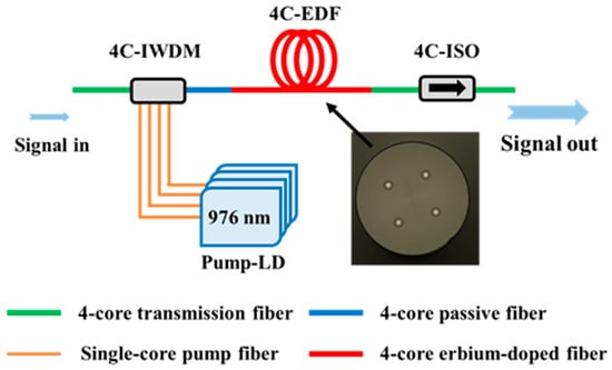
Figure 1.
Schematic of the core-pumped 4C-EDFA. 4C-IWDM: 4-core hybrid isolator and wavelength-division multiplexer; Pump-LD: Pump laser diode; 4C-EDF: 4-core erbium-doped fiber; 4C-ISO: 4-core isolator.
First, we characterize the key components, i.e., the 4C-EDF and the 4-core passive devices, to demonstrate their low inter-core difference. Figure 1 shows the cross-section of the 4C-EDF, and its key parameters are listed in Table 1. The measured core pitches for the four cores are 43.00 μm, 42.75 μm, 43.04 μm, and 43.03 μm, respectively, with a maximum variation of 0.29 μm and a standard deviation (SD) of 0.138 μm. To measure the absorption coefficients of the 4C-EDF, the cutback method is employed []. A pair of 4-core fan-in/fan-out (4C-FIFO) fabricated by the fused taper process is used in the measurement []. The 4CF used in the 4C-FIFO has the same MFD and core pitch as the 4C-EDF, and the inter-core XT is <−60 dB. In this way, the influence of splice loss and device XT on the measurement results is negligible. Through six sets of repeated tests, the peak absorption coefficients for the four cores are 6.10 dB/m, 6.12 dB/m, 6.26 dB/m, and 6.31 dB/m, respectively. Importantly, the core-dependent absorption coefficient remains <0.21 dB/m, with an SD of 0.103 dB/m across the four cores, which ensures a low DCG in the amplifier.

Table 1.
Key parameters of the fabricated 4C-EDF.
The 4C-IWDM is implemented based on free-space optics and integrates collimating lenses, a Faraday rotator, and a beam combiner, which provides both optical isolation and 976/1550 nm wavelength-division multiplexing. As shown in Figure 2a, the 4C-IWDM contains one signal input port, four pump input ports, and one common output port. The signals from the input 4CF and the pump lights emitted from four single-mode 976 nm LDs are first collimated and then directed into the WDM. After multiplexing, both the signal and pump beams are focused onto the facet of the output 4-core passive fiber by a common collimator. The isolator, placed between the input port and the WDM, can suppress backward amplified spontaneous emission (ASE) noise. During fabrication, the output 4-core passive fiber is continuously rotated to find a low CDL. For the insertion loss (IL) measurement, the input and output power of each core are measured using a 4C-FIFO assembly to guide light. The measured IL across the C-band is shown in Figure 2b, the average IL of the 4C-IWDM for the four cores are 0.63 dB, 0.65 dB, 0.65 dB, and 0.58 dB, and the maximum IL values for the four cores are <0.7 dB, with a maximum CDL of 0.12 dB observed at 1550 nm, a minimal CDL of 0.06 dB observed at 1535 nm, and an SD of 0.006 dB. Note that the wavelength-dependent loss (WDL) for each core is also very low, i.e., 0.11 dB, 0.10 dB, 0.08 dB, and 0.05 dB, respectively. The average IL for the pump lights is 1.75 dB. Furthermore, the inter-core XT of these key passive devices is measured by injecting light into one core and detecting the output power from all others. This measurement is conducted using a tunable laser source (TSL) and an optical power meter, with the device under test connected via a pair of low-XT (<−54 dB) 4C-FIFO. The 4C-IWDM exhibits a minimum isolation of 56 dB and a maximum inter-core XT of −57 dB.
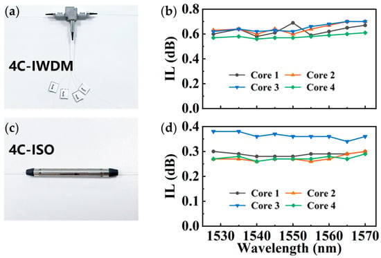
Figure 2.
Prototype image and measured IL values of (a,b) the 4C-IWDM and (c,d) the 4C-ISO. These two components exhibit high inter-core consistency and low WDL. For the 4C-IWDM, the maximum IL for the four cores is <0.7 dB, with a maximum CDL of 0.12 dB observed at 1550 nm. The WDL is <0.11 dB. For the 4C-ISO, the maximum IL for the four cores is <0.38 dB, with a maximum CDL of 0.09 dB observed at 1528 nm. The WDL is <0.04 dB.
The 4C-ISO is also implemented based on free-space optics, as shown in Figure 2c. It is placed at the output of the 4C-EDFA to suppress backward ASE by preventing it from re-entering the 4C-EDF, which effectively reduces the NF. The measured IL of the device across the C-band is shown in Figure 2d. The maximum IL values for the four cores are as low as 0.38 dB, with a maximum CDL of 0.09 dB and an SD of 0.047dB. The WDLs for all four cores are less than 0.04 dB. Furthermore, the 4C-ISO exhibits a minimum isolation of 59 dB and a maximum inter-core XT of −48 dB. These results demonstrate that both the fabricated 4C-IWDM and 4C-ISO possess high inter-core consistency and low WDL across the whole C-band.
3. Characterization of the 4C-EDFA
Figure 3a illustrates the experimental setup used to characterize the proposed 4C-EDFA. Fifty-one tunable laser sources TLSs are used to cover the wavelength range from 1528 nm to 1569 nm with a uniform channel spacing of 0.8 nm. A variable optical attenuator (VOA) is placed after each TLS to precisely control the per-channel output power, which ensures a power flatness within ±0.1 dB across all wavelength channels. These channels are then combined to form a 51 λ light output serving as the input signal to the 4C-EDFA, and the corresponding spectrum is shown in Figure 3b. An additional VOA is placed between the combined source and the 4C-FI to adjust the total signal power launched into each core of the 4C-EDFA to 7 dBm/core, which is typical in long-haul transmission systems across the whole C-band [,]. A pair of 4C-FIFO is used to characterize the gain and NF of each core, and its impact has been excluded. Its 4CF has the same structural parameters as that of the 4C-EDFA, which ensures low splice loss between them. At the output of the 4C-EDFA, an optical spectrum analyzer (OSA) is used to record the amplified output spectrum.
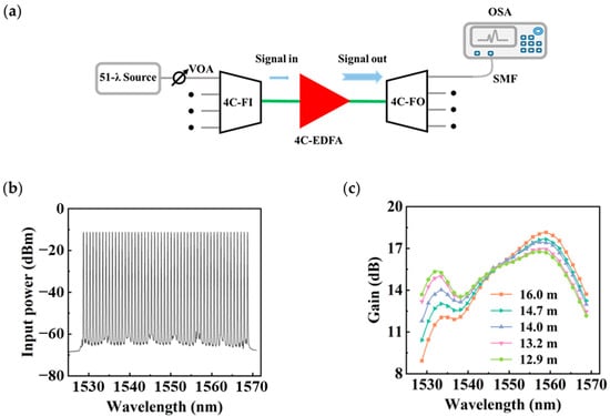
Figure 3.
(a) Experimental setup for the proposed 4C-EDFA; (b) optical spectrum of the input signal; and (c) gain as a function of wavelength under different fiber lengths of the 4C-EDF. The optimal length of the 4C-EDF is determined to be 12.9 m. SMF: Single-mode fiber; VOA: Variable optical attenuator; 4C-FI/FO: 4-core fan-in/fan-out; 4C-EDFA: 4-core erbium-doped fiber amplifier; OSA: Optical spectrum analyzer.
To determine the optimal length of the 4C-EDF, we initially set the fiber length to 16 m and gradually shortened it. The output spectra are recorded and compared to evaluate the amplifier performance. According to refs. [,], the 4C-EDFA should provide a gain of >12 dB across the whole C-band to compensate for the loss of a fiber span as well as additional losses from passive components and splices. As shown in Figure 3c, as the length of the 4C-EDF decreases, the gain at shorter wavelengths increases gradually, whereas the gain at longer wavelengths decreases. At a length of 12.9 m, the gain exceeds 12 dB across the whole C-band. Therefore, this length is selected as the optimal 4C-EDF length for the amplifier.
Figure 4a shows the measured gain and DCG of the 4C-EDFA across the wavelength range of 1528–1569 nm. With pump powers individually optimized to 527.7 mW, 566.6 mW, 523.4 mW, and 486.5 mW for each core of the 4C-EDF, the DCG is minimized, with an average input pump power of 789.1 mW/core before the 4C-IWDM. Over this wavelength range, the maximum and minimum gains of the proposed 4C-EDFA are 17.47 dB and 12.60 dB, respectively, corresponding to a gain ripple of ~5 dB. The average gains for the four cores are 15.60 dB, 15.39 dB, 15.44 dB, and 15.70 dB, respectively, with a spectrally averaged DCG of 0.31 dB, and the average total signal output power reaches 22.5 dBm. The 4C-EDFA exhibits a maximum DCG of 0.50 dB at 1569 nm, which is attributed to the use of all key components with low inter-core differences. The total power conversion efficiency (PCE) is calculated to be 21.9%. A potential method to further improve the PCE is to reduce the loss of the 4C-IWDM for the pump light. For example, if this loss is decreased from the current 1.75 dB to 0.5 dB, the PCE can be enhanced from 21.9% to 29.9%. Figure 4b shows a maximum NF of 4.91 dB and an inter-core variation of <0.12 dB across the C-band, resulting from the low-loss 4C-IWDM combined with the forward 976 nm core-pumping. A further reduction in NF remains feasible by minimizing the signal light loss in the 4C-IWDM.
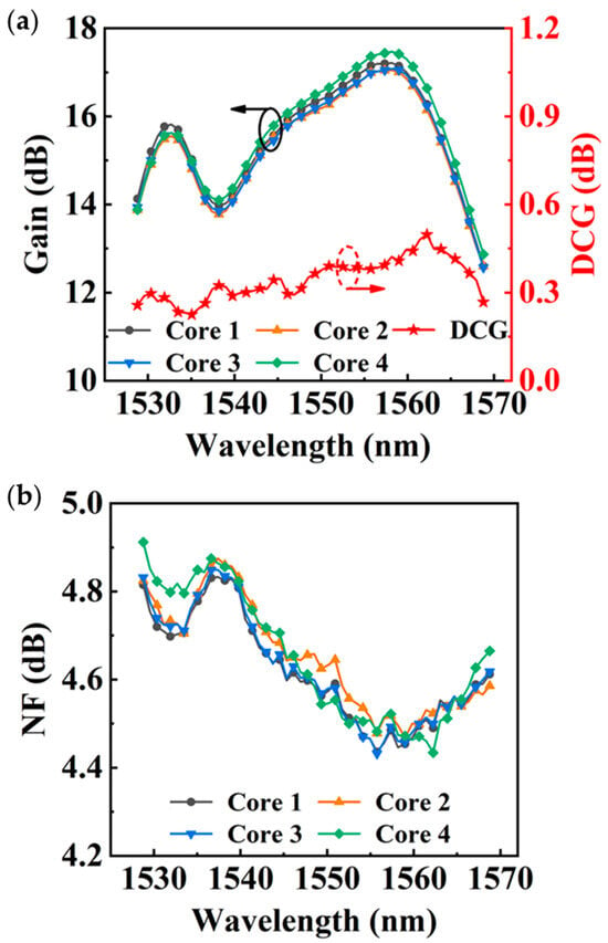
Figure 4.
(a) Gain, DCG, and (b) NF of the 4C-EDFA as a function of wavelength. The 4C-EDFA exhibits a maximum DCG of 0.50 dB at 1569 nm. This ultra-low DCG is attributed to the use of all key components with low inter-core differences. In addition, the maximum NF is as low as 4.91 dB.
Representative studies on uncoupled 4C-EDFAs are summarized in Table 2. The pump compensation method is widely used to reduce the DCG [,,,], with a reported low of 0.7 dB. However, the DCG’s further reduction is constrained by inherent core-to-core discrepancies in the 4C-EDF and passive devices. By utilizing a 4C-EDF with a minimal core-dependent absorption coefficient and optimized 4-core passive devices with minimal CDL, we have achieved a record-low DCG of <0.5 dB. Meanwhile, the proposed 4C-EDFA also exhibits high output, low NF across the whole C-band.

Table 2.
Comparison of integrated 4C-EDFAs.
4. Transmission Results and Discussions
To evaluate the transmission performance of the proposed 4C-EDFA, we conduct a numerical simulation of a long-haul SDM system based on the Gaussian-noise model [,]. The system model, illustrated in Figure 5a, consists of multiple cascaded fiber spans. The 4CF is configured with the following parameters: a loss of 0.16 dB/km, a chromatic dispersion of 20 ps/(nm·km), an inter-core XT of −70 dB/km, and an effective mode area of 80 μm2. A 34-GBaud 128 λ polarization-division multiplexed quadrature phase-shift keying (PDM-QPSK) signal is transmitted through the 4CF, amplified by the 4C-EDFA, and shaped by a gain-flattening filter (GFF). In the system model, the measured broadband gain and NF for each core of the 4C-EDFA are applied to all wavelength channels within that respective core. The Q2 factors for all signals are estimated at the receiver. For a given DCG, the gains of the four cores are set to follow an arithmetic progression to emulate the DCG. Figure 5b shows the maximum transmission distance calculated based on the 25.5% overhead forward error correction (FEC) threshold, corresponding to a Q2 limit of 5 dB []. The results show an approximately linear decrease in maximum transmission distance as DCG increases. Benefiting from the low DCG of 0.50 dB offered by the proposed 4C-EDFA, the system can achieve a maximum transmission distance exceeding 10,000 km. The inter-core Q2 differences (ΔQ2s) among the four cores at a transmission distance of 10,000 km are shown in Figure 5c. The performance difference between the cores increases with DCG. Note that the ΔQ2 induced by the proposed 4C-EDFA with a DCG of 0.5 dB is only 0.5 dB, which emphasizes the importance of a low DCG for achieving uniform performance across all cores.
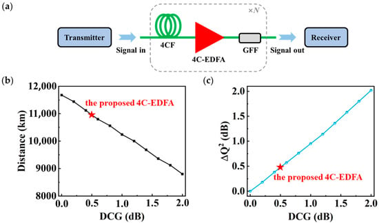
Figure 5.
(a) Setup for the 4CF transmission link employing 4C-EDFAs; (b) maximum transmission distance and (c) ΔQ2 among cores at 10,000 km as a function of DCG. The proposed 4C-EDFA enables a maximum transmission distance exceeding 10,000 km. When the DCG of the 4C-EDFA is 0.5 dB, the ΔQ2 among cores is ~0.5 dB, which demonstrates the importance of a low DCG for achieving uniform performance across all cores.
5. Conclusions
In conclusion, we have experimentally demonstrated an integrated 4C-EDFA in a 976 nm core-pumped scheme, which achieves a record-low DCG of 0.5 dB. The low DCG is realized by minimizing the core-dependent absorption coefficient of the 4C-EDF to 0.21 dB/m, as well as reducing the CDLs of the integrated 4-core passive devices to 0.12 dB for the 4C-IWDM and 0.09 dB for the 4C-ISO. The 4C-EDFA also achieves an average gain of 15.50 dB, a maximum NF of 4.91 dB, and an average output power of 22.5 dBm across the whole C-band. Furthermore, through a 34-GBaud PDM-QPSK transmission simulation over a 4CF link, the proposed 4C-EDFA is shown to be able to support transmission distances exceeding 10,000 km, and ΔQ2 is only 0.5 dB. These results confirm that the proposed 4C-EDFA exhibits low DCG, low NF, and high output power, demonstrating its potential in high-capacity and long-haul uncoupled MCF systems.
Author Contributions
Conceptualization, M.L., B.Z., T.X. and Y.L.; methodology, M.L., Y.W. (Yanze Wang), T.X. and B.Z.; software, M.L. and Y.W. (Yanpu Wang); validation, Y.W. (Yan Wang) and Y.S.; formal analysis, M.L., B.Z., T.X. and X.L.; investigation, M.L. and X.L.; resources, Y.L. and Y.W. (Yan Wang); data curation, M.L., Y.W. (Yanze Wang), Y.S., X.L. and Y.W. (Yanpu Wang); writing—original draft preparation, M.L.; writing—review and editing, Y.W. (Yanze Wang), Y.L. and Z.Y.; visualization, M.L. and J.L.; supervision, Y.L., S.Z., L.M., J.L., Y.W. (Yan Wang), Y.W. (Yanpu Wang), Z.Y. and Z.H.; project administration, Y.L., S.Z., L.M., J.L., Y.W. (Yan Wang), Z.Y. and Z.H.; funding acquisition, Y.L., S.Z. and Z.Y. All authors have read and agreed to the published version of the manuscript.
Funding
This work is supported by the National Natural Science Foundation of China (62405217), Tianjin Natural Science Foundation (23JCQNJC01580), and National Key R&D Program of Sichuan Province, China (2025YFHZ0020).
Data Availability Statement
The data of our study are available upon request.
Conflicts of Interest
Author Shigui Zhang, Liping Ma, Jianping Li, Yan Wang, Yue Shao, Xiaochuan Liu, and Yanpu Wang were employed by HMN Technologies Co., Ltd. The remaining authors declare that the research was conducted in the absence of any commercial or financial relationships that could be construed as a potential conflict of interest. We confirm that this affiliation did not influence the objectivity of the research or the interpretation of the results.
References
- Winzer, P.J.; Neilson, D.T.; Chraplyvy, A.R. Fiber-Optic Transmission and Networking: The Previous 20 and the next 20 Years [Invited]. Opt. Express 2018, 26, 24190. [Google Scholar] [CrossRef] [PubMed]
- Puttnam, B.J.; Rademacher, G.; Luís, R.S. Space-Division Multiplexing for Optical Fiber Communications. Optica 2021, 8, 1186. [Google Scholar] [CrossRef]
- Matsui, T.; Pondillo, P.L.; Nakajima, K. Weakly Coupled Multicore Fiber Technology, Deployment, and Systems. Proc. IEEE 2022, 110, 1772–1785. [Google Scholar] [CrossRef]
- Takahashi, M.; Maeda, K.; Aiso, K.; Mukasa, K.; Sugizaki, R.; Soma, D.; Takahashi, H.; Tsuritani, T.; Mitrovic, M.; Palsdottir, B.; et al. Uncoupled 4-Core Fibre with Ultra-Low Loss and Low Inter Core Crosstalk. In Proceedings of the 2020 European Conference on Optical Communications (ECOC), Brussels, Belgium, 6–10 December 2020; IEEE: Piscataway, NJ, USA, 2020; pp. 1–4. [Google Scholar]
- Matsui, T.; Sagae, Y.; Yamada, Y.; Nakajima, K.; Matsuo, Y.; Inoue, T.; Katayama, K.; Inada, Y. High Figure–of–Merit Multi–Core Fiber with Standard Cladding Diameter for Long–Haul and Wide–Band Transmission. J. Lightwave Technol. 2024, 42, 4124–4131. [Google Scholar] [CrossRef]
- Tandon, P.; Bennett, K.; Tuggle, M.; Butler, D.; De Pedro, H.; Hebgen, P.; Sutton, C.; Matthews, H.B.; Drake, M.; Johnson, S.; et al. Record Low Loss 0.144 dB/Km 2-Core Optical Fiber for Submarine Transmission. J. Lightwave Technol. 2024, 42, 4213–4221. [Google Scholar] [CrossRef]
- Zahidy, M.; Ribezzo, D.; De Lazzari, C.; Vagniluca, I.; Biagi, N.; Müller, R.; Occhipinti, T.; Oxenløwe, L.K.; Galili, M.; Hayashi, T.; et al. Practical High-Dimensional Quantum Key Distribution Protocol over Deployed Multicore Fiber. Nat. Commun. 2024, 15, 1651. [Google Scholar] [CrossRef] [PubMed]
- Soma, D.; Beppu, S.; Wakayama, Y.; Sumita, S.; Takahashi, H.; Yoshikane, N.; Morita, I.; Tsuritani, T.; Suzuki, M. Trans-Pacific Class Transmission over a Standard Cladding Ultralow-Loss 4-Core Fiber. Opt. Express 2022, 30, 9482. [Google Scholar] [CrossRef] [PubMed]
- Yan, H.; Liu, H.; Du, W.; Wang, Y.; Yuan, S.; Wang, Y.; Chen, M.; Sun, W.; Lao, X.; Zhang, G.; et al. Record Long-Haul Transmission with FIFO-Less Multicore EDFA Over 125-Μm Cladding MCF. In Proceedings of the 2023 Asia Communications and Photonics Conference/2023 International Photonics and Optoelectronics Meetings (ACP/POEM), Wuhan, China, 4–7 November 2023; IEEE: Piscataway, NJ, USA, 2023; pp. 1–4. [Google Scholar]
- Soma, D.; Beppu, S.; Galdino, L.; Lorenz, M.; Ma, Q.; Iwasaki, K.; Sumita, S.; Komatsu, K.; Elson, D.J.; Kiriyama, T.; et al. 18,090-Km 2-Core Fiber Transmission Using Circulatory Directional Fan-in/Fan-out Devices. In Proceedings of the Optical Fiber Communication Conference (OFC) 2024, San Diego, CA, USA, 24–28 March 2024; Optica Publishing Group: Washington, DC, USA, 2024; p. Th4A.4. [Google Scholar]
- Di Sciullo, G.; Puttnam, B.J.; Hout, M.V.D.; Luís, R.S.; Shaji, D.A.; Rademacher, G.; Okonkwo, C.; Mecozzi, A.; Antonelli, C.; Furukawa, H. 45.7 Tb/s Over 12 053 Km Transmission in an All-Multi-Core-Amplified Recirculating Loop. J. Lightwave Technol. 2025, 43, 4635–4641. [Google Scholar] [CrossRef]
- Kobayashi, Y.; Hayashi, T. Behavior and Measurement Method of Inter-Core Crosstalk in Multicore Fibers with Core-Dependent Loss. Opt. Express 2023, 31, 502. [Google Scholar] [CrossRef] [PubMed]
- Cartaxo, A.V.T. Loss Imbalance Effect on Inter-Core Crosstalk in Bidirectional Uncoupled Multi-Core Fiber Transmission. J. Lightwave Technol. 2023, 41, 5911–5921. [Google Scholar] [CrossRef]
- Takeshita, H.; Nakamura, K.; Matsuo, Y.; Inoue, T.; Masuda, D.; Hiwatashi, T.; Hosokawa, K.; Inada, Y.; De Gabory, E.L.T. Demonstration of Uncoupled 4-Core Multicore Fiber in Submarine Cable Prototype with Integrated Multicore EDFA. J. Lightwave Technol. 2023, 41, 980–988. [Google Scholar] [CrossRef]
- Du, W.; Liu, H.; Bai, Y.; Xu, B.; Zhang, W.; Xu, W. FIFO-Less Core-Pumped Multicore Erbium-Doped Fiber Amplifier with Hybrid Passive Components. In Proceedings of the 2023 Opto-Electronics and Communications Conference (OECC), Shanghai, China, 2–6 July 2023; IEEE: Piscataway, NJ, USA, 2023; pp. 1–3. [Google Scholar]
- Ohtsuka, T.; Kikuchi, T.; Suganuma, T.; Hasegawa, T.; Tazawa, H. Power Efficient Core Pumped Multicore Erbium Doped Optical Fiber Amplifier. In Proceedings of the 2023 Optical Fiber Communications Conference and Exhibition (OFC), San Diego, CA, USA, 5–9 March 2023; IEEE: Piscataway, NJ, USA, 2023; pp. 1–3. [Google Scholar]
- Gu, Z.; He, L.; Yin, X.; Liu, S.; Li, W.; Xing, Y.; Dai, N.; Li, J. M-Type Refractive Index Profile Erbium-Doped Fiber for High-Efficiency Multicore EDFA. Opt. Express 2024, 32, 7564. [Google Scholar] [CrossRef] [PubMed]
- Liang, S.; Downie, J.D.; Makovejs, S.; Davidson, I.A.; Choudhury, N.; Kakaei, Z.; Sahu, J.; Petropoulos, P.; Jung, Y. Novel Core-Pumped Multicore Fiber Amplifier Integrated with Energy-Efficient Pump Light Distributor. In Proceedings of the 2025 Optical Fiber Communications Conference and Exhibition (OFC), San Francisco, CA, USA, 30 March–3 April 2025; IEEE: Piscataway, NJ, USA, 2025; pp. 1–3. [Google Scholar]
- Takeshita, H.; Shimomura, Y.; Maeda, W. Bidirectional 4-Core MC-EDFA Featuring Integrated Optical Components and Inter-Core Optical Loopback Function. In Proceedings of the 2025 Optical Fiber Communications Conference and Exhibition (OFC), San Francisco, CA, USA, 30 March–3 April 2025; IEEE: Piscataway, NJ, USA, 2025; pp. 1–3. [Google Scholar]
- Bsaibes, M.; Deduytschaever, M.; Kudinova, M.; Trinel, J.-B.; Sillard, P.; Autebert, C.; Labroille, G.; Perrier, P.; Andresen, E.R.; Quiquempois, Y.; et al. Impact of Fluctuations of Er-Doped Preforms Properties on the Performances of Multi-Core Amplifiers for Submarine Applications. In Proceedings of the 2025 Optical Fiber Communications Conference and Exhibition (OFC), San Francisco, CA, USA, 30 March–3 April 2025; IEEE: Piscataway, NJ, USA, 2025; pp. 1–3. [Google Scholar]
- Feng, H.; Jalilpiran, S.; Maes, F.; Wang, L.; LaRochelle, S. Characterization of Giles Parameters for Extended L-Band Erbium-Doped Fibers. J. Opt. Soc. Am. B 2022, 39, 1783. [Google Scholar] [CrossRef]
- Ji, W.; Shen, Z.; Yu, R.; Wang, C.; Yan, Z.; Liu, L.; Xu, L.; Chen, W.; Chiang, K.S.; Xiao, L. Spacing-Tailored Multicore Fiber Interface for Efficient FIFO Devices. J. Lightwave Technol. 2022, 40, 5682–5688. [Google Scholar] [CrossRef]
- Abedin, K.S.; Taunay, T.F.; Fishteyn, M.; Yan, M.F.; Zhu, B.; Fini, J.M.; Monberg, E.M.; Dimarcello, F.V.; Wisk, P.W. Amplification and Noise Properties of an Erbium-Doped Multicore Fiber Amplifier. Opt. Express 2011, 19, 16715. [Google Scholar] [CrossRef] [PubMed]
- Qi, J.; Ding, Y.; Chu, G.; Dai, G.; Zhai, R.; Shen, L.; Zhang, L.; Zhong, L.; Luo, J. Four-Core Erbium-Doped Fiber Amplifier for Space Division Multiplexing Transmission. In Proceedings of the Fourteenth International Conference on Information Optics and Photonics (CIOP 2023), Xi’an, China, 24 November 2023; Yang, Y., Ed.; SPIE: Bremerhaven, Germany, 2023; p. 215. [Google Scholar]
- Poggiolini, P. The GN Model of Non-Linear Propagation in Uncompensated Coherent Optical Systems. J. Lightwave Technol. 2012, 30, 3857–3879. [Google Scholar] [CrossRef]
- Gene, J.M.; Winzer, P.J. A Universal Specification for Multicore Fiber Crosstalk. IEEE Photon. Technol. Lett. 2019, 31, 673–676. [Google Scholar] [CrossRef]
- Sugihara, K.; Miyata, Y.; Sugihara, T.; Kubo, K.; Yoshida, H.; Matsumoto, W.; Mizuochi, T. A Spatially-Coupled Type LDPC Code with an NCG of 12 dB for Optical Transmission beyond 100 Gb/s. In Proceedings of the Optical Fiber Communication Conference/National Fiber Optic Engineers Conference 2013, Anaheim, CA, USA, 17–21 March 2023; OSA: Navarra, Spain, 2013; p. OM2B.4. [Google Scholar]
Disclaimer/Publisher’s Note: The statements, opinions and data contained in all publications are solely those of the individual author(s) and contributor(s) and not of MDPI and/or the editor(s). MDPI and/or the editor(s) disclaim responsibility for any injury to people or property resulting from any ideas, methods, instructions or products referred to in the content. |
© 2025 by the authors. Licensee MDPI, Basel, Switzerland. This article is an open access article distributed under the terms and conditions of the Creative Commons Attribution (CC BY) license (https://creativecommons.org/licenses/by/4.0/).