Abstract
Visible light communication (VLC) has emerged as one promising candidate technique to improve the throughput performance in future sixth-generation (6G) mobile communication networks. Due to the limited battery capacity of VLC systems, light energy harvesting has been proposed and incorporated for achieving the simultaneous lightwave information and power transfer (SLIPT) function and for improving the overall energy efficiency. Nevertheless, almost all reported works are limited to SLIPT scenarios adopting a basic and well-discussed Lambertian optical transmitter, which definitely cannot characterize the potential and essential scenarios employing distinctive non-Lambertian optical transmitters with various spatial beam characteristics. For addressing this issue, in this work, SLIPT based on a distinct non-Lambertian optical beam configuration is investigated, and for further enhancing the harvested energy and the achievable data rate, the relevant flexible optical beam configuration method is presented as well. The numerical results show that, for a typical receiver position, compared with about 1.14 mJ harvested energy and a 31.2 Mbps achievable data rate of the baseline Lambertian configuration, a harvested energy gain of up to 1.55 mJ and an achievable data rate gain of 21.1 Mbps can be achieved by the non-Lambertian SLIPT scheme explored here.
1. Introduction
Visible light communication (VLC) is increasingly viewed as one powerful candidate solution to effectively mitigate and address the severe spectrum scarcity in the upcoming sixth-generation (6G) telecommunication networks [1,2,3,4,5]. Particularly, VLC can utilize ubiquitous light-emitting diode (LED)-based illumination infrastructures, which make it more competitive in capital expenditures (CAPEX) than setting one totally new radio frequency (RF) network [6,7,8,9,10]. At the same time, it must be noted that in evolving mobile networks, due to their relatively finite battery capacity, it is quite challenging for mobile terminals to provide consistent communication performance over long durations. For tackling this energy supply issue and exploring the power transfer potential of VLC, light-energy-harvesting-enabled VLC systems, also known as simultaneous lightwave information and power transfer (SLIPT) systems, are proposed and have gained lots of research interest [11,12,13,14,15]. In typical SLIPT, the emitted optical signals are utilized for data transmission and power transfer at the same time [16,17,18,19,20,21].
Recently, a multitude of SLIPT systems and variants have been investigated and reported [17,18,19,20,21]. The authors in [10] developed an optimization framework in order to tune the LED average currents for improving the SLIPT system performance. Moreover, the study [9] considered one SLIPT-enabled multiple-input single-output (MISO) VLC network for multiple users and formulated one achievable sum rate maximization problem by joint optimization. In addition, the authors in [12] proposed one performance optimization scheme for the multi-cell SLIPT system employing field of view (FoV)-tunable receivers, and the optical concentration ratio of the FoV was derived as well. Objectively, researchers have introduced a series of design and optimization methods to SLIPT systems, including but not limited to hybrid visible light communication (VLC)/radio frequency (RF) modes [15], dual-hop transmission [16], non-linearity of responsivity [17], resource allocation [18], beamforming design [19], fairness aware [20], and relay selection [21].
Nevertheless, up to now, almost all these SLIPT articles assume that the involved LED sources follow well-known Lambertian emission beams [22,23,24], which does not reflect the potential applications of SLIPT based on distinct non-Lambertian optical beams. On the other hand, non-Lambertian emission beam effects and relevant potential gains have earned lots of interest in many research branches of the VLC domain, especially including but not limited to cell planning, access point design, the characterization of channel characteristics, coordinated coverage, multiple optical beam switching, and hybrid VLC and RF transmission. Based on the above review, for meeting the diverse SLIPT application needs with more flexible optical beam configurations, filling the research gap of the existent SLIPT works from the spatial optical beam point of view is urgently needed.
Considering the above situation, in this paper, to the best of our knowledge, the fundamental performance characteristics of non-Lambertian optical beams employing SLIPT are explored for 6G VLC systems for the first time. At the same time, the effect of beam azimuth rotation is estimated in order to enhance the energy harvesting performance of the involved SLIPT correspondingly.
In this paper, distinct optical beam configurations based on SLIPT are presented in Section 2. The derivative flexible optical beam configuration method is investigated in Section 3. Numerical results are provided and analyzed in Section 4. Finally, Section 5 concludes this article.
In summary, the main contributions of the article are as follows: the system models and mathematical descriptions of distinct non-Lambertian beams based on the SLIPT scheme are provided for the first time, and the fundamental performance metrics are comparatively analyzed between the baseline Lambertian SLIPT scheme and the proposed non-Lambertian SLIPT schemes. Moreover, the effects of the receiver aperture size, the emitted signal intensity, and the beam azimuth rotation are numerically investigated for the concerned SLIPT schemes with distinct beam configurations.
2. SLIPT Based on Baseline Lambertian Optical Beam Configurations
To a large extent, the SLIPT channel quality and coverage performance are dominated by the optical emission pattern of a light emitting diode (LED) transmitter. Objectively, these distinct beam patterns open one novel design and optimization dimension for enhancing the SLIPT performance.
2.1. Baseline Lambertian Optical Channel Model
In a typical SLIPT system, from the information source view, m(t) represents the modulated electrical signal, which corresponds to the bit stream. To ensure the non-negativity of the emitted signal, one direct current (DC) bias is added to m(t) before being applied to modulate the LED optical intensity and drive the LED in the desired operation mode. Accordingly, the emitted lightwave signal from the lighted LED is [10]
where PLED denotes the LED optical power per unit current (in W/A) of instantaneous electrical current + m(t) at this optical emitter. The instantaneous signal varies around the added DC bias [IL, IH] with peak current amplitude A, where IL denotes the minimum and IH denotes the maximum input bias current, respectively. For avoiding clipping distortion by the LED non-linearity, and to restrain the electrical signal input to the LED within the linear operation region, the following limitation is derived [10]:
In one typical indoor application scenario, the proportion of the non-line-of-sight transmission path component is much weaker than that of line-of-sight transmission path. For simplifying the analysis, this work merely considers the contribution of the line-of-sight transmission path. Therefore, when the emission characteristic of the LED source matches the Lambertian emission beam, the channel gain at the optical receiver can be given as [10,22]
where Lr is the detection area of the receiver; d is the distance between the LED optical source and the receiver; is the irradiance angle from the optical source; is the incident angle to the receiver; and denotes the receiver field of view (FOV). And denotes the gain of the optical filter and denotes the gain of the optical concentrator, given by [10,22]:
where is the optical refractive index of the concentrator. As presented in (3), the Lambertian radiation intensity is the key metric to measure the Lambertian spatial emission characteristics of LED beams in the VLC channel gain, as given by
where is the Lambertian index, and it can be given by
where is the emission semi-angle of the LED. Since the Lambertian index is set as 1, the respective 3D emission pattern is illustrated in Figure 1. In this figure, one typical SLIPT indoor scenario with a single Lambertian beam is illustrated as well. By substituting (5) and (4) into (3), the baseline Lambertian optical channel gain for SLIPT should be renewed as
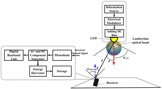
Figure 1.
Schematic of SLIPT based on baseline Lambertian emission beam for 6G IoT network.
2.2. Baseline Lambertian Received Electrical SNR
When a Lambertian optical beam is applied to configure the SLIPT link, the respective electrical current from the output of the photodiode (PD) at the optical receiver should be given as [10]
where is the PD responsivity in A/W, denotes the generated DC component from this Lambertian optical source, is the generated alternating current (AC) component from this Lambertian optical source, and denotes the additive white Gaussian noise (AWGN), which is mainly induced from the thermal noise and the background shot noise.
Specifically, denotes the generated AC component due to the Lambertian source and can be explicitly given by
Therefore, the derived signal-to-noise ratio (SNR) should be given as [10]
where denotes the noise power at the PD receiver.
In addition to the abovementioned performance metrics, the tight lower bounds of the achievable data rate should be expressed as [25]
where B denotes the bandwidth of the system.
2.3. Baseline Lambertian Energy Harvesting Model
For the baseline Lambertian energy harvesting model, as mentioned in the above content, the generated photocurrent includes both DC and AC signals. For performing energy harvesting under the baseline Lambertian optical beam configuration, the respective DC component is blocked by one capacitor and then passes through the energy harvesting branch. The harvested energy from the Lambertian optical beam can be given by [10]
where f is the fill factor and being the DC component from the output current can be given as
Moreover, the concerned open-circuit voltage can be identified following [10]
where is the thermal voltage and is the dark saturation current of the PD at the VLC receiver.
3. SLIPT Based on LUXEON Rebel Non-Lambertian Optical Beam Configurations
3.1. LUXEON Rebel Non-Lambertian Optical Channel Model
Different from the well-discussed conventional Lambertian emission beam, the spatial radiation intensity of the non-Lambertian emission beams provides distinct spatial selectivity for the emitted optical signal [23,24]. Without the loss in generality as in one typical rotationally symmetric non-Lambertian optical beam, the counterpart from the LUXEON Rebel LED is elaborately selected for the following investigation in this section. The reason for this selection is that on one hand, this non-Lambertian beam has quite distinct spatial emission characteristics compared with the conventional Lambertian light beams, but on the other hand, this non-Lambertian emission beam is inherited by a commercially available LED, which ensures this work is applicable in future engineering implementations.
In one typical indoor scenario, once the emission characteristic of the optical source matches the LUXEON Rebel non-Lambertian beam, the SLIPT channel gain at the receiver can be given as [23,24]
where is the power normalization factor of the LUXEON Rebel emission beam, which functions to ensure that the total optical power emitted in 3D spatial directions is 1 W, and is the spatial emission intensity of the LUXEON Rebel beam, which can be described by the following expression as one sum of multiple Gaussian functions [23,24]:
where is the emission angle and N1 = 2 is the number of Gaussian functions. Specifically, the values of the coefficients in this expression are as follows: = 0.76, = 0°, = 29°, = 1.10, = 45°, and = 21°. From the side view, Figure 2 illustrates the 3D emission patterns of this LUXEON Rebel non-Lambertian emission beam with rotational symmetry. Unlike the previous Lambertian emission beam, in this non-Lambertian case, the maximum intensity could no longer be found in the normal direction, i.e., the red arrow direction, but at all directions with an approximate 40° irradiance angle. By substituting (17) and (4) into (16), this non-Lambertian optical wireless channel gain for SLIPT can be renewed as
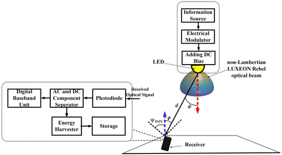
Figure 2.
Schematic of SLIPT based on LUXEON Rebel emission beam for 6G IoT network.
3.2. LUXEON Rebel Non-Lambertian Received Electrical SNR
Similarly, when the LUXEON Rebel non-Lambertian emission beam is applied to configure the SLIPT link, the respective electrical current output of the photodiode (PD) receiver should be given as
where denotes the generated DC component from the LUXEON Rebel non-Lambertian LED and denotes the generated alternating current (AC) component from the non-Lambertian LUXEON Rebel optical source.
Specifically, under this non-Lambertian LUXEON Rebel SLIPT link setting, the generated AC component can be explicitly given by
Therefore, the derived SNR for this LUXEON Rebel non-Lambertian SLIPT configuration can be given as
Accordingly, the tight lower bounds of the achievable data rate for this LUXEON Rebel non-Lambertian case can be expressed as
3.3. LUXEON Rebel Non-Lambertian Energy Harvesting Model
For the non-Lambertian LUXEON Rebel energy harvesting model, as introduced in the above content, the generated photocurrent includes both AC and DC signals. For performing energy harvesting under the non-Lambertian LUXEON Rebel emission beam configuration, the respective DC portion can also be successfully blocked by one capacitor and then passes through the energy harvesting branch. The harvested energy from the non-Lambertian LUXEON Rebel emission beam can be given by
where is the respective DC component of the output current under the non-Lambertian LUXEON Rebel emission beam configuration. Specifically, the expression of should be explicitly given by
Moreover, the concerned open-circuit voltage for this LUXEON Rebel non-Lambertian case can be identified as the following:
4. SLIPT Based on Asymmetric NSPW Non-Lambertian Optical Beam Configurations
4.1. Asymmetric NSPW Non-Lambertian Optical Channel Model
Unlike the Lambertian emission beam and the LUXEON Rebel emission beam, the spatial radiation pattern of the NSPW345CS Nichia LED is not rotationally symmetric any more. It should be noted that the NSPW in the following work is not one abbreviation, but one popular model from an international LED manufacturer. Thanks to this novel beam asymmetry, the non-Lambertian NSPW345CS Nichia LED is deliberately selected for the following discussion in this section. For convenience, NSPW is used to present this LED product type in this article. Obviously, the NSPW non-Lambertian optical beam provides much different spatial radiation characteristics compared with the baseline Lambertian emission beam, and this asymmetric optical beam from the representative commercially available LED can assure that the following work is applicable in engineering implementations.
In the envisioned typical indoor scenario, when the radiation characteristic of the LED source matches the non-Lambertian asymmetric NSPW beam, the relevant SLIPT channel gain at the receiver can be given as [23,24]
where denotes the normalization factor of the asymmetric NSPW emission beam, which works to ensure that the optical power radiated in all spatial directions is 1 W, and is the spatial radiation intensity of the asymmetric NSPW emission beam, which can be profiled by the following expression as one sum of multiple Gaussian functions [23,24]:
where α is the azimuth angle and the left coefficient values of the Gaussian functions are given as = 0.13, = 45°, = = 18°, = 1, = 0, = 38°, and = 22°. Similarly, the 3D description of the NSPW345CS UB emission beam is illustrated in Figure 3. By substituting (28) and (4) into (27), this non-Lambertian asymmetric NSPW optical wireless channel gain for SLIPT can be renewed as
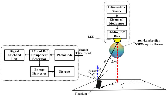
Figure 3.
Schematic of SLIPT based on asymmetric NSPW emission beam for 6G IoT network.
4.2. Asymmetric NSPW Non-Lambertian Received Electrical SINR
When the non-Lambertian asymmetric NSPW emission beam is utilized to configure the SLIPT link, the respective instantaneous electrical current at the receiver output can be given as
where denotes the generated instantaneous DC component from the asymmetric NSPW non-Lambertian optical source and is the generated instantaneous alternating current (AC) component from the non-Lambertian asymmetric NSPW optical source.
Specifically, under this non-Lambertian asymmetric NSPW SLIPT link configuration, the generated instantaneous AC component can be explicitly given by
Therefore, the derived SNR for this asymmetric NSPW non-Lambertian SLIPT configuration can be given as
Accordingly, the tight lower bounds of the achievable data rate for this non-Lambertian NSPW case should be expressed as
4.3. Asymmetric NSPW Non-Lambertian Energy Harvesting Model
For the asymmetric NSPW non-Lambertian energy harvesting model, as mentioned above, the generated photocurrent consists of both AC and DC signals simultaneously. For performing energy harvesting under the non-Lambertian asymmetric NSPW emission beam configuration, the relevant DC component should also be blocked by one capacitor and then passes through the energy harvesting branch. The harvested energy from the asymmetric NSPW non-Lambertian optical beam can be given by
where is the respective DC component from the output current under the non-Lambertian asymmetric NSPW emission beam configuration. Specifically, the expression of can be explicitly given by
Moreover, the concerned open-circuit voltage for this asymmetric NSPW non-Lambertian case can be identified in the following:
5. Numerical Evaluation
In this section, a performance analysis is conducted between the baseline Lambertian and non-Lambertian emission beam configuration based on SLIPT for 6G VLC systems. Specifically, one typical medium-sized indoor scenario is envisioned. Furthermore, the concerned main parameters are presented in Table 1, which is mainly consistent with the well-reported work of SLIPT in [10,25].

Table 1.
Main parameter configuration.
In this SLIPT application scenario, the LED-based transmitter is mounted at the ceiling center with the normal direction pointing to the ground. As for the receiver end, the ground is chosen as the receiver working plane, which represents the most challenging vertical distance between the LED transmitter and the optical receiver within the considered indoor scenario. Without the loss of generality, for the receiver end, the normal direction is always vertically upward to the ceiling plane independent of certain locations.
For the convenience of an analysis and a comparison of SLIPT, three typical receiver geometry locations are adopted, including the central position, i.e., (2.5, 2.5, 0) m, the side position, i.e., (2.5, 0.5, 0) m, and the corner position, i.e., (0.5, 0.5, 0) m. Unlike the mentioned Lambertian and non-Lambertian LUXEON Rebel emission beam configuration for SLIPT, the non-Lambertian NSPW emission beam configuration could not match the rotational symmetry from the view of the spatial emission pattern; therefore, the side position close to the neighbor sidewall should be chosen as one additional side position, i.e., side position 2 with coordinates (0.5, 2.5, 0) m, for sufficient exploration in the following comparative evaluation.
5.1. Effect of Receiver Aperture Size
In this subsection, the receiver aperture effect on the performance of SLIPT adopting the distinct optical beam configuration is investigated. Regarding the achievable rate, as shown in Figure 4, for all cases, the achievable rate can be enhanced by increasing the receiver aperture size since more optical signal flux can be captured by the enlarged aperture area. Specifically, for the central position with the best channel condition, the non-Lambertian NSPW emission beam configuration can consistently provide a more superior transmission performance than the other two beam configurations via focusing more emitted optical intensity in the normal direction, while the counterpart of the LUXEON Rebel non-Lambertian beam configuration is lowest since more emitted optical intensity is inherently designed to light more ubiquitous surrounding directions but not the unusual normal direction. Numerically, when the receiver aperture size is 10 cm2, the achievable rates are 31.2 Mbps, 18.1 Mbps, and 52.3 Mbps for the cases of Lambertian, Rebel non-Lambertian, and NSPW non-Lambertian, respectively. An achievable data rate gain up to 21.1 Mbps can be provided by the proposed non-Lambertian NSPW SLIPT scheme. Once the receiver aperture size is increased to 100 cm2, the respective performance metric is enhanced to 95.8 Mbps, 79.7 Mbps, and 118.2 Mbps with increments of 64.6 Mbps, 61.6 Mbps, and 65.9 Mbps for the three cases. For the corner position, the non-Lambertian LUXEON Rebel beam configuration outperforms the other two beam configurations since more light power is emitted to these surrounding edge areas. As for the left case of the side position, when the original receiver aperture size of 10 cm2 is applied, the best performance of 27.1 Mbps is derived for the non-Lambertian NSPW emission beam configuration with the receiver located at side position 2 since the narrow cross-section of this beam naturally projects more power to this position; this is at the price of projecting limited power to the nearby side position with the worst performance of 10.4 Mbps. When the final receiver aperture size of 100 cm2 is applied, the achievable rate performance for side position 2 and the side position is gradually increased to 91.2 Mbps and 67.3 Mbps, respectively. Objectively, for the concerned positions, the minimum achievable rate difference, i.e., the achievable rate fluctuation, can be observed adopting the LUXEON Rebel beam configuration, while the most intense rate fluctuation can be identified for the case of the NSPW beam. Apparently, under the NSPW non-Lambertian configuration, since more emitted power is concentrated in the normal direction of the LED, more optical power can be accordingly captured by the receiver that is located at the normal-facing position, i.e., the center position.
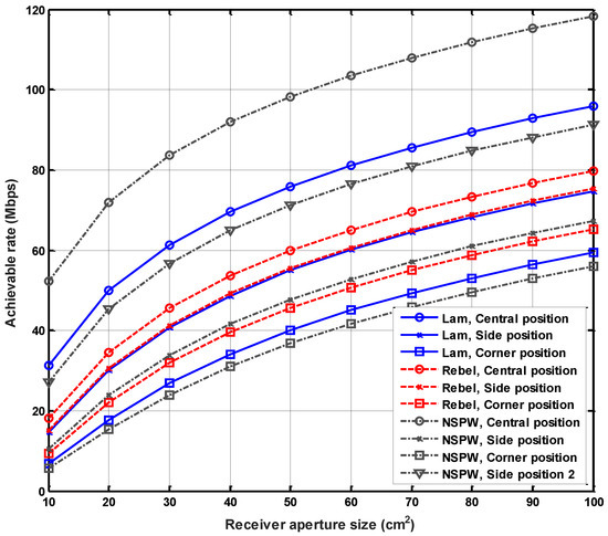
Figure 4.
Comparison of achievable rate versus receiver aperture size for SLIPT with distinct optical beam configuration.
As for the performance of energy harvesting of SLIPT, a similar trend can be observed, as shown in Figure 5. It should be noted that there is a more obvious harvested energy gap between the different beam configurations for the same position. Specifically, for the center position, when the original receiver aperture size of 10 cm2 is applied, the harvested energy is 1.14 mJ, 0.61 mJ, and 2.69 mJ for the Lambertian emission beam configuration, the LUXEON Rebel beam configuration, and the NSPW beam configuration, respectively, with a harvested energy gap of 0.53 mJ between the Lambertian configuration and the LUXEON Rebel configuration and a harvested energy gap of 1.55 mJ between the NSPW configuration and the Lambertian configuration. A harvested energy gain of up to 1.55 mJ can be provided by the discussed non-Lambertian SLIPT scheme compared with the harvested energy of the benchmark Lambertian configuration. When the receiver aperture size is increased to 100 cm2, the harvested energy is enlarged to 14.3 mJ, 7.76 mJ, and 33.4 mJ for the three mentioned beam configurations, respectively, while a counterpart of 6.54 mJ in the harvested energy gap can be observed between the Lambertian configuration and the LUXEON Rebel configuration and a counterpart of 19.1 mJ in the harvested energy can be found between the NSPW configuration and the Lambertian configuration.
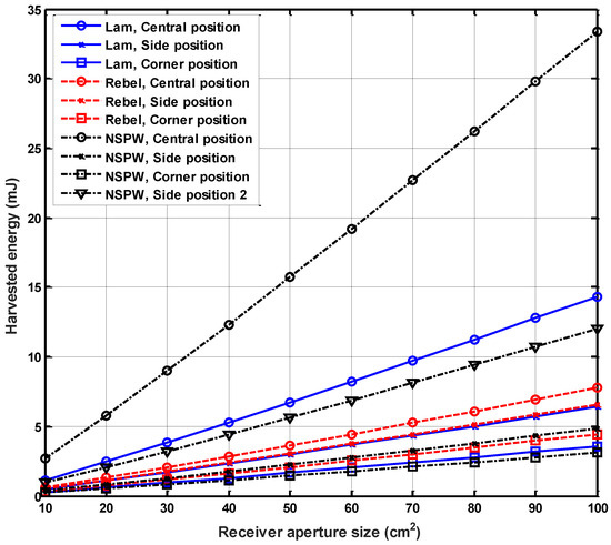
Figure 5.
Comparison of harvested energy versus receiver aperture size for SLIPT with distinct optical beam configuration.
5.2. Effect of Emitted Signal Intensity
In this subsection, the effect of the emitted signal intensity on the performance of SLIPT adopting a distinct optical beam configuration is investigated. In the aspect of achievable rate performance, a similar trend can be observed. As shown in Figure 6, when the original emitted signal intensity in the electrical domain is 0.6 mA, the achievable rates are 31.2 Mbps, 18.1 Mbps, and 52.3 Mbps for the cases of Lambertian, non-Lambertian Rebel, and non-Lambertian NSPW, respectively, at the central position. Once the emitted signal intensity is linearly increased to 6 mA, the respective performance metric is enhanced to 95.8 Mbps, 70.7 Mbps, and 118.2 Mbps with an increment of 64.6 Mbps, 52.6 Mbps, and 65.9 Mbps for the three cases.
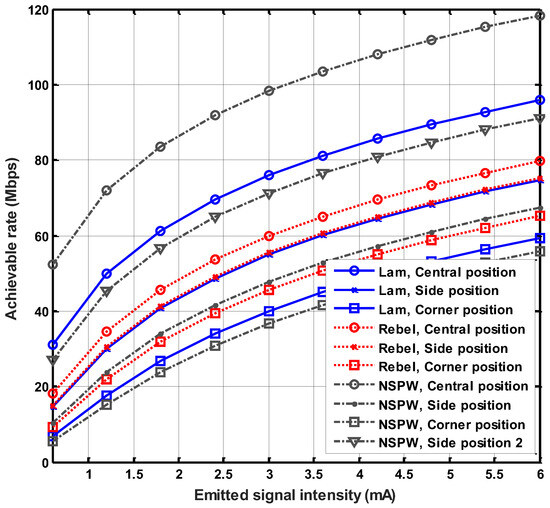
Figure 6.
Comparison of achievable rate versus emitted signal intensity for SLIPT with distinct optical beam configuration.
Nevertheless, unlike the effect of receiver aperture size, the harvested energy amount is independent of the emitted signal intensity since only the DC component but not the AC component, i.e., the emitted signal, is utilized for energy harvesting, as shown in Figure 7.
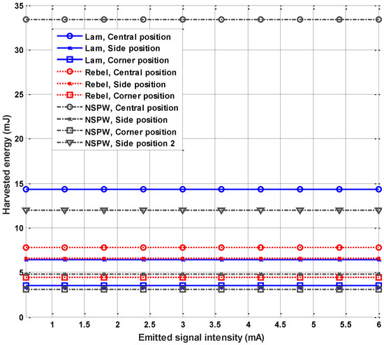
Figure 7.
Comparison of harvested energy versus emitted signal intensity for SLIPT with distinct optical beam configuration.
5.3. Effect of Beam Azimuth Rotation
In this subsection, the effect of the azimuth rotation angle on the performance of SLIPT adopting the distinct optical beam configuration is investigated. Specifically, as shown in Figure 1 and Figure 2, the spatial emission patterns of the Lambertian and the LUXEON Rebel non-Lambertian beam configurations render obvious rotational symmetry since the achievable rate and the harvested energy at any receiver positions are independent of the azimuth rotation angle manually manipulated to these two optical beam configurations with rotational symmetry.
As for the left non-Lambertian NSPW configuration, an apparent nonrotational symmetry can be observed in Figure 3. Therefore, the performance of SLIPT adopting this unique optical beam configuration will be significantly affected by the manually manipulated azimuth rotation angle. Numerically, as shown in Figure 8, for the central position, the achievable rate performance is constant for all azimuth rotation angles since the receiver is on the normal axis of the LED transmitter, in other words, just under the transmitter mounted on the ceiling. For the left candidate receiver positions, obvious periodicity in the achievable rate performance can be observed with the increased azimuth rotation angle, as shown in Figure 8. Although the rotation angle cycle is 90° for the side position, corner position, and side position 2, a different achievable rate performance appears under the same azimuth rotation angle. Specifically, for the original azimuth rotation angle of 0°, a maximum achievable rate of 91.2 Mbps is obtained for side position 2, while a minimum achievable rate of 67.3 Mbps is obtained for the side position, which means that an achievable rate variation up to 23.9 Mbps can be realized by manipulation of the azimuth rotation angle. Then, with the azimuth rotation angle increased to about 50°, a respective maximum achievable rate of 70.2 Mbps is obtained for the corner position. Once the azimuth rotation angle is increased to about 90°, a maximum achievable rate of 91.2 Mbps is obtained for the side position. All these phenomena indicate that by manipulating the azimuth rotation angle of the NSPW non-Lambertian configuration, the achievable rate of the SLIPT system can be enhanced or degraded on purpose significantly. It must be noted that, in this work, the discussion is limited to the effect of the beam azimuth rotation on the distinct beam configurations, which could be unintentionally induced during the mounting of the LED transmitter on the ceiling surface. This fundamental investigation is essential, especially for the NSPW non-Lambertian configuration with the rotated asymmetrical radiation characteristic. As for the potential intentional manipulation of the azimuth rotation and the relevant method design, both are beyond the discussion scope of this article and can be left for future systematic investigations by incorporating micro-electromechanical systems, liquid crystals, metamaterials, or other enabling techniques.
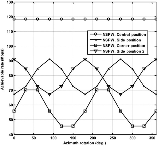
Figure 8.
Comparison of achievable rate versus azimuth rotation angle for SLIPT with typical rotating asymmetric beam configuration.
As for the performance of energy harvesting for the SLIPT system, a similar variation can be observed as well, as illustrated in Figure 9. Specifically, for side position 2, a maximum harvested energy of 12.0 mJ and a minimum harvested energy of 4.84 mJ appear when the rotation angles of 0° and 90° are introduced separately, which means that an harvested energy variation up to 7.16 mJ can be realized by manipulation of the azimuth rotation angle. The metrics for this variation amplitude are 7.16 mJ and 2.31 mJ for the side position and corner position, respectively. A similarity can be observed between Figure 8 and Figure 9. The main cause for these phenomena is that SLIPT channels under the NSPW non-Lambertian configuration for DC and AC signal transmission are simultaneously analogously varied by the potential azimuth rotation. Hence, the harvested energy and the achievable transmission rate via the SLIPT channels are similarly varied accordingly.
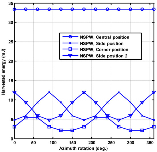
Figure 9.
Comparison of harvested energy versus azimuth rotation angle for SLIPT with typical rotating asymmetric beam configuration.
6. Conclusions
This work is motivated by the applicability limitation of the conventional Lambertian SLIPT VLC research paradigm, which could not adapt to the potential non-Lambertian SLIPT VLC scenarios. In this article, the representative commercially available non-Lambertian beams are adopted to configure the SLIPT VLC links. For the case of NSPW non-Lambertian SLIPT VLC, an achievable rate variation of up to 23.9 Mbps and a harvested energy variation of 7.16 mJ can be realized by manipulation of the azimuth rotation angle. In the near future, work for 6G green networks and the exploration of distinct Non-Lambertian optical beam configurations based on SLIPT for VLC could be further extended to the customized dynamic beam configuration, resource allocation, beam steering, beam cooperation, beam switching, reconfigurable multiple-input multiple-output networks, and other design techniques.
Author Contributions
J.D. determined the theme and structure of the article, provided professional knowledge in the field of visible light communications, wrote and modified the article, and replied to comments from editors and reviewers. C.-L.I. provided theoretical knowledge of mobile communication and wireless communication. J.W. found the literature, participated in the discussion, and wrote some of the content. J.S. looked for literature, participated in the discussion, and wrote some of the content. All authors have read and agreed to the published version of the manuscript.
Funding
This work was supported in part by the National Natural Science Foundation of China (Grants No. 62061043), Tianshan Cedar Project of Xinjiang Uygur Autonomous Region (Grants No. 2020XS27), and High-level Talents Introduction Project in Autonomous Region (Grants No. 042419004).
Institutional Review Board Statement
Not applicable.
Informed Consent Statement
Not applicable.
Data Availability Statement
Data are contained within the article.
Conflicts of Interest
The authors declare no conflicts of interest.
References
- Zhang, Y.; Zhang, H.; Cosmas, J.; Jawad, N.; Ali, K.; Meunier, B.; Kapovits, A.; Huang, L.-K.; Li, W.; Shi, L. Internet of radio and light: 5G building network radio and edge architecture. Intell. Converg. Netw. 2020, 1, 37–57. [Google Scholar] [CrossRef]
- Celik, A.; Romdhane, I.; Kaddoum, G.; Eltawil, A. A Top-Down Survey on Optical Wireless Communications for the Internet of Things. IEEE Commun. Surv. Tutor. 2023, 25, 1–45. [Google Scholar] [CrossRef]
- Ding, J.; Liu, W.; I, C.-L.; Zhang, H.; Mei, H. Advanced Progress of Optical Wireless Technologies for Power Industry: An Overview. Appl. Sci. 2020, 10, 6463. [Google Scholar] [CrossRef]
- Palitharathna, K.W.S.; Suraweera, H.A.; Godaliyadda, R.I.; Herath, V.R.; Ding, Z. Neural-Network-Based Blockage Prediction and Optimization in Lightwave Power-Transfer-Enabled Hybrid VLC/RF Systems. IEEE Internet Things J. 2024, 11, 5237–5248. [Google Scholar] [CrossRef]
- Palitharathna, K.W.S.; Wickramasinghe, N.D.; Vegni, A.M.; Suraweera, H.A. Neural Network-Based Optimization for SLIPT-Enabled Indoor VLC Systems With Energy Constraints. IEEE Trans. Green Commun. Netw. 2024, 8, 839–851. [Google Scholar] [CrossRef]
- Santos, D.R.D. Toward Indoor Simulations of OPV Cells for Visible Light Communication and Energy Harvesting. IEEE Access 2024, 12, 41027–41041. [Google Scholar] [CrossRef]
- Chowdhury, M.Z.; Hossan, M.T.; Islam, A.; Jang, Y.M. A comparative survey of optical wireless technologies: Architectures and applications. IEEE Access 2018, 6, 9819–9840. [Google Scholar] [CrossRef]
- Hamza, A.S.; Deogun, J.S.; Alexander, D.R. Classification framework for free space optical communication links and systems. IEEE Commun. Surveys Tuts. 2019, 21, 1346–1382. [Google Scholar] [CrossRef]
- Ma, S.; Zhang, F.; Zhou, F.; Wang, Y.; Li, S. Simultaneous Lightwave Information and Power Transfer in Visible Light Communication Systems. IEEE Trans. Wirel. Commun. 2019, 18, 5818–5830. [Google Scholar] [CrossRef]
- Diamantoulakis, P.D.; Karagiannidis, G.K.; Ding, Z. Simultaneous Lightwave Information and Power Transfer (SLIPT). IEEE Trans. Green Commun. Netw. 2018, 2, 764–773. [Google Scholar] [CrossRef]
- Morapitiya, S.; Ali, M.; Rajkumar, S.; Wijayasekara, S.; Jayakody, D.; Weerasuriya, R. A SLIPT-assisted Visible Light Communication Scheme. In Proceedings of the 2020 16th International Conference on Distributed Computing in Sensor Systems (DCOSS), Marina del Rey, CA, USA, 25–27 May 2020; IEEE: New York, NY, USA, 2020. [Google Scholar]
- Abdelhady, A.; Amin, O.; Shihada, B.; Alouini, M. On the Optimization of Multi-Cell SLIPT System. In Proceedings of the 2018 IEEE Global Communications Conference (GLOBECOM), Abu Dhabi, United Arab Emirates, 9–13 December 2018; IEEE: New York, NY, USA, 2018. [Google Scholar]
- Guo, Y.; Xiong, K.; Lu, Y.; Gao, B.; Fan, P.; Letaief, K. SLIPT-enabled Multi-LED MU-MISO VLC Networks: Joint Beamforming and DC Bias Optimization. IEEE Trans. Green Commun. Netw. 2022, 6, 1104–1120. [Google Scholar] [CrossRef]
- Abdelhady, A.; Amin, O.; Shihada, B.; Alouini, M. Spectral Efficiency and Energy Harvesting in Multi-cell SLIPT Systems. IEEE Trans. Wirel. Commun. 2020, 19, 3304–3318. [Google Scholar] [CrossRef]
- Huang, S.; Chuai, G.; Gao, W.; Zhang, K. Agency selling format-based incentive scheme in cooperative hybrid VLC/RF IoT system with SLIPT. IEEE Internet Things J. 2023, 10, 7366–7379. [Google Scholar] [CrossRef]
- Peng, H.; Li, Q.; Pandharipande, A.; Ge, X.; Zhang, J. End-to-End Performance Optimization of a Dual-Hop Hybrid VLC/RF IoT System Based on SLIPT. IEEE Internet Things J. 2021, 8, 17356–17371. [Google Scholar] [CrossRef]
- Alqahtani, D.; Chen, Y.; Feng, W. Practical Non-Linear Responsivity Model and Outage Analysis for SLIPT/RF Networks. IEEE Trans. Veh. Technol. 2021, 70, 6778–6787. [Google Scholar] [CrossRef]
- Zargari, S.; Kolivand, M.; Nezamalhosseini, S.; Abolhassani, B.; Chen, L.; Kahaei, M. Resource Allocation of Hybrid VLC/RF Systems with Light Energy Harvesting. IEEE Trans. Green Commun. Netw. 2022, 6, 600–612. [Google Scholar] [CrossRef]
- Xiaodong, L.; Wang, Y.; Zhou, F.; Ma, S.; Hu, R.; Ng, D.W.K. Beamforming Design for Secure MISO Visible Light Communication Networks with SLIPT. IEEE Trans. Commun. 2020, 68, 7795–7809. [Google Scholar]
- Girdher, A.; Gupta, N.; Bansal, A. Fairness-Aware Energy Harvesting in RSMA-Aided MU-MISO VLC Network. IEEE Commun. Lett. 2024, 28, 1062–1066. [Google Scholar] [CrossRef]
- Zhang, Z.; Li, Q.; Peng, H.; Pandharipande, A.; Ge, X.; Zhang, J. A SLIPT-Based Hybrid VLC/RF Cooperative Communication System with Relay Selection. In Proceedings of the 2021 IEEE/CIC International Conference on Communications in China (ICCC), Negombo, Sri Lanka, 11–13 August 2019; IEEE: New York, NY, USA, 2019. [Google Scholar]
- Komine, T.; Nakagawa, M. Fundamental analysis for visible-light communication system using LED lights. IEEE Trans. Consum. Electron. 2004, 50, 100–107. [Google Scholar] [CrossRef]
- Moreno, I.; Sun, C.-C. Modeling the radiation pattern of LEDs. Opt. Exp. 2008, 16, 1808–1819. [Google Scholar] [CrossRef]
- Ding, J.; Chih-Lin, I.; Xu, Z. Indoor optical wireless channel characteristics with distinct source radiation patterns. IEEE Photonics J. 2016, 8, 7900115. [Google Scholar] [CrossRef]
- Tennakoon, P.; Jayakody, D.N.K.; Affes, S. Simultaneous Lightwave Information and Power Transfer with Non-orthogonal Multiple Access. In Proceedings of the 2021 10th International Conference on Information and Automation for Sustainability (ICIAfS), Negambo, Sri Lanka, 11–13 August 2021; pp. 214–219. [Google Scholar]
Disclaimer/Publisher’s Note: The statements, opinions and data contained in all publications are solely those of the individual author(s) and contributor(s) and not of MDPI and/or the editor(s). MDPI and/or the editor(s) disclaim responsibility for any injury to people or property resulting from any ideas, methods, instructions or products referred to in the content. |
© 2024 by the authors. Licensee MDPI, Basel, Switzerland. This article is an open access article distributed under the terms and conditions of the Creative Commons Attribution (CC BY) license (https://creativecommons.org/licenses/by/4.0/).