Article

Simulation and Experimental Study of Nanosecond Pulse Laser Removal of Epoxy Paint on 6061 Aluminum Alloy Surface

1
Jilin Key Laboratory of Solid-State Laser Technology and Application, School of Physical Sciences, Changchun University of Science and Technology, Changchun 130022, China
2
School of Electrical and Electronic Engineering, Changchun University of Technology, Changchun 130012, China
*
Authors to whom correspondence should be addressed.
Photonics 2024, 11(1), 25; https://doi.org/10.3390/photonics11010025
Submission received: 31 October 2023 / Revised: 8 December 2023 / Accepted: 14 December 2023 / Published: 27 December 2023
(This article belongs to the Special Issue Optical Precision Manufacturing and Processing)

Abstract

:
Laser paint removal is a new cleaning technology that mainly removes paint through thermal ablation and mechanical stripping mechanisms. This paper established a thermal-mechanical coupling laser removal model of paint based on the heat conduction equation, Newton’s second law, and Fabbro’s theory. The removal process of epoxy resin paint film on an aluminum alloy surface via a nanosecond pulsed laser was studied using finite element simulations and experimental measurements. The simulation and experimental results show that the nanosecond pulse laser’s primary paint removal mechanism is the mechanical stripping caused by thermal stress and plasma shock. The laser paint removal threshold is 1.4 J/cm2. In addition, due to the different generation times of plasma shock and thermal stress, the mutual superposition of stress waves occurs in the material. This results in a discrepancy between the actual and thermal stress differences. Moreover, the thermal stress difference causes the maximum actual stress difference to fluctuate. The simulation model established in this paper can provide a reference for studying the thermal-mechanical coupling process of laser paint removal.

1. Introduction

In the industrial field, large equipment surfaces are painted to prevent the corrosion of the underlying material. Due to the influence of the environment, when the paint film ages and falls off, it is necessary to remove and repaint. Traditional mechanical and chemical cleaning techniques have the disadvantages of easily damaging the substrate and polluting the environment. Green, environmentally friendly, high-precision laser cleaning technology can replace traditional cleaning technology. Laser cleaning technology is widely used in aviation [1,2], shipping [3,4], and automotive [5,6] industries. The main mechanisms of laser paint removal are ablation, thermal stress stripping, and plasma shock [7]. These mechanisms can be mainly divided into the following two categories: ablation and stripping mechanisms. Since the efficiency and effect of laser paint removal are related to the paint removal mechanism, studying its mechanism can improve the efficiency and effect of laser paint removal.
In recent years, much research has been carried out on the mechanism of laser paint removal. F Brygo et al. found that the heat accumulation effect can increase the laser ablation efficiency of paints and reduce the laser ablation threshold [8]. Zhao et al. found that the primary laser removal of the paint film from aluminum alloy surface mechanisms was ablation, thermal stress stripping, and plasma shock [7]. Thermal stress stripping was the best removal mechanism [9]. Zheng et al. found that the mechanism of laser paint removal in compressed air and inert gas is the laser gasification effect and thermal stress effect [10]. Zhang et al. found that at a higher laser fluence, the surface roughness of the substrate decreases significantly due to surface melting [11].
In addition, the optimal mechanism for laser paint removal depends on the laser parameters and the paint composition. Roberts et al. found that the laser paint removal mechanism is related to paint film thickness [12]. Kumar et al. found that the laser paint removal mechanism depends on laser wavelength [13]. Tong et al. compared the paint removal efficiency of the Gaussian laser and the flat-top laser and found that the paint removal efficiency of the flat-top laser was 20% higher than that of the Gaussian laser [14]. Sun et al. found that thermal ablation and thermal vibration at the edge of the cleaning area significantly increased the paint removal width to improve the paint removal efficiency [15]. Lu et al. established a nanosecond laser thermal stress cleaning model considering the absorption of the laser by plasma [16]. Zhang et al. found that the mechanism of paint removal for laser-transparent and opaque paint films was thermal stress stripping and ablation, respectively [17]. Therefore, the mechanism of laser paint removal also needs to be discussed in detail for different kinds of material, pollutants, and parameters.
To study the mechanism of pulse laser paint removal, we used the finite element method to study the thermal-mechanical coupling process in laser paint removal. Dimitriou et al. used experiments and finite element methods to study the spatiotemporal evolution process of thermoelastic vibrations, melting, and ablation when the nanosecond laser irradiates thin films. It was found that combining theoretical models and experimental techniques can describe the transient deformation of material surfaces [18]. Gao et al. combined theory and experiment to study the thermal coupling process of 6061 aluminum alloy irradiated by a nanosecond pulse laser and found that the primary mechanism of material surface damage is melting and spattering [19]. Therefore, we can deeply understand the laser paint removal mechanism by combining theoretical and experimental research.
Research on laser paint removal mainly focuses on a single mechanism, such as ablation, thermal stress stripping, and plasma shock. There are few studies on the thermal-mechanical coupling process of laser paint removal. Therefore, studying the thermal-mechanical coupling process of laser paint removal can reveal the primary mechanism of nanosecond laser paint removal.
This paper establishes a thermal-mechanical coupling model for nanosecond laser paint removal based on the heat conduction theory, Newton’s second law, and Fabbro’s theory. The novelty of this work lies in establishing the theory and simulation model of laser thermal-mechanical coupling paint removal. The thermal stress and plasma shock effects on the laser paint removal process were studied theoretically and experimentally. It is worth noting that thermal stress significantly affects the laser paint removal process. The mechanism of laser paint removal can be deeply understood through the thermal-mechanical coupling model of laser paint removal.

2. Theoretical Model

The paint removal process for the nanosecond laser includes ablation, thermal stress, plasma shock, and other phenomena. According to physical processes, the paint removal mechanisms of ablation, thermal stress, and plasma shock can be divided into thermal ablation and stress-stripping. The gasification of the paint film due to high temperatures is called thermal ablation. The paint film’s thermal stress and plasma shock stripping is called stress stripping. Because these three mechanisms affect the paint removal process, it is necessary to study the effect of these mechanisms on the paint removal process. We developed a model for the thermal-mechanical coupling laser removal of paint because the paint film and aluminum alloy substrate are isotropic materials. A two-dimensional axisymmetric model can be used to describe the laser paint removal process.

2.1. Ablation Process

In the process of laser paint removal, the temperature of the paint film absorbing laser energy rises and ablates. Since the nanosecond laser pulse width is short, the heat loss from gasification is much more significant than the natural heat convection and thermal radiation caused by temperature differences. Therefore, the heat loss caused by convective heat transfer and heat radiation can be ignored during laser paint removal. The heat conduction equation can be expressed as follows [20,21]:
ρ C T t ( k T ) = Q n s + q 0 ,
Q n s = A ζ ( r ) ( e / τ π r 1 2 ) e x p ( ( t τ τ 0 ) ) e x p ( κ p ν p ( t τ 0 ) ) τ 0 < t < 2 τ + τ 0 ,
ζ ( r ) = { 0 e l s e 1 r 1 > r > 0 ,
q 0 = v ρ Δ H v ,
where Qns is the laser heat source, q0 is the energy loss caused by evaporation, r1 is the spot radius of the pulsed laser, A is the laser absorption rate of the paint film, and v is the gasification rate of materials. τ is the laser pulse width, τ0 = τ/2 is the laser incident time, e is the laser energy, ζ(r) is the spatial distribution function of the laser spot, ρ, C, and k are the density, specific heat capacity, and thermal conductivity of the material, respectively, κp is the plume absorption coefficient, νp is the plume expansion velocity, r is the distance from the center of the spot, T is the temperature of the material, and ΔHv is the latent heat of gasification.
The gasification rate v of the material can be calculated using the Hertz–Knudsen equation [22],
v = 0.82 m 2 π k b p s a t ( T ) T ,
p s a t ( T ) = P 0 e x p [ Δ H v k b ( 1 T b 1 T ) ] ,
where m is the atomic mass of the material, kb is the Boltzmann constant, Tb is the evaporation temperature of the paint film, and P0 is the standard atmospheric pressure.
Because the paint film is in close contact with the substrate, its contact surface temperature is the same. The boundary conditions can be expressed as follows:
T p ( r , l 1 , t ) = T s ( r , l 1 , t ) ,
where l1 is the thickness of the paint film material, and the subscripts s and p represent the aluminum alloy substrate and the epoxy resin paint film, respectively.
The initial condition can be expressed as follows:
T ( r , z , 0 ) = 293.25 K ,
where z is the depth of material.

2.2. Mechanical Stripping Process

According to Newton’s second law, the governing equation for the propagation of stress waves in solid materials can be expressed as follows:
ρ 2 u t 2 = σ ,
where σ and u are the stress tensor and displacement vector.
The surface of the paint film is subjected to shock pressure during the laser paint removal process. Shock pressure pulses last 2–3 times longer than laser pulses. The laser shock pressure waveform follows a Gaussian distribution [23]. The plasma shock wave pressure can be expressed as follows [24]:
P ( r , z , t ) = P ( t τ 0 τ 0 ) e x p ( 1 ( t τ 0 τ 0 ) ) δ 2 ( r , z )   t > τ 0 ,
δ 2 ( r , z ) = { 1 0 < r < r 1 , z = 0 0 e l s e ,
where δ2 is the step function.
Based on Fabbro’s model [25,26], the peak pressure of the shock wave caused by the laser-plasma shock wave can be expressed as follows [27,28]:
P = α 2 α + 3 Z 1 m a x ( Q n s ( t ) ) ,
Z i = ρ i D i ( i = 1 , 2 ) ,
D i = V i + S i u i ( i = 1 , 2 ) ,
where α is the energy ratio for the gas ionization, Z is the sound impedance, u is the speed of material motion, S is a dimensionless coefficient, D is the shock wave velocity, and V is the speed of sound. i = 1, 2 represents the paint film and the aluminum substrate, respectively.
Since air is the confining layer, we assumed α ≈ 0.1. The speed of material movement during laser paint removal is much less than the speed of sound of the material, assuming that the shock wave speed of the material is equal to the speed of sound, DV.
The relationship between pressure and material stress can be expressed as follows:
σ n = P ( r , z , t ) n + G : ( β ( T T 0 ) ) n ,
where n represents the ordinary units, β is the thermal expansion coefficient, T is the material temperature, T0 = 293.15 K is the initial temperature of the material, G is the 2nd order elasticity tensor, and “:” is the double-dot tensor product.
Stress waves are reflected and transmitted at the interface between the paint film and the aluminum alloy substrate [29,30]. This is assuming that ideal contact is made between the paint film and the substrate. According to the interaction model between the stress wave and the interface, the stress waves can be calculated as follows [31]:
P r = Z 2 Z 1 Z 2 + Z 1 σ ,
P t = 2 Z 2 Z 2 + Z 1 σ ,
where Pr and Pt are the reflection and transmission stress waves at the interface between the paint film and substrate, respectively.
Since the shear stress on the plane containing the axis of symmetry (z-axis) in the axisymmetric coordinate system is zero (σ = σ = 0), the relationship between the stress and strain of the material can be expressed as follows:
σ = G : ε ,
( σ r σ z σ θ σ r z ) = [ λ + 2 μ λ λ 0 λ λ + 2 μ λ 0 λ λ λ + 2 μ 0 0 0 0 μ ] ( ε r ε z ε θ ε r z ) ,
λ = E i ν i / ( 1 + ν i ) ( 1 2 ν i ) ,
μ = E i / 2 ( 1 + ν i ) ,
where ε is the Strain tensor, λ, and μ are the first and second Lame parameters, ν is Poisson’s ratio, and E is Young’s modulus.
The boundary conditions are shown below:
P r | z = 0 = P r | z = ( l 1 + l 2 ) = σ ,
P t | z = ( l 1 + l 2 ) = P t | z = 0 = 0 ,
where l2 is the thickness of the aluminum alloy substrate.
Because the stress wave propagates inside the material, to simplify the model set the material’s right boundary as a low reflection boundary. It can be expressed as follows:
σ n | r = d = ρ i c p ( u t n ) n ρ i c s ( u t t ) t ,
c p = E i ρ i ( 1 ν i ) ( 1 + ν i ) ( 1 2 ν i ) ,
c s = E i 2 ρ i ( 1 + ν i ) ,
where t represents the tangential vectors at the boundary. The cp and cs are the speeds of the pressure and shear waves in the material. d is the length of the material of the finite element model.
The initial conditions can be obtained as
σ ( r , z , t ) | t = 0 = 0 .

2.3. Paint Film Removal Conditions

Since the laser paint removal process involves the separation of the paint film from the substrate and the fracture between the paint films, the laser paint removal threshold is the maximum value of these two processes [31].
The transmitted stress wave at the interface between the paint film and the substrate is in the opposite direction to the reflected stress wave. The stress difference ΔP between these two stress waves causes the paint to separate from the substrate. This is obtained by calculating the Hugoniot elastic limit (HEL). The separation condition between the paint film and the substrate can be expressed as follows:
Δ P i = λ + 2 μ 2 μ F w ,
where i = 1, 2, 3 represent the actual stress, thermal stress, and plasma shock stress, respectively; Fw is the adhesion strength between the epoxy resin paint film and the aluminum alloy substrate, which is 18.9 MPa [32].
When the stress difference ΔPr at the boundary of the paint film exceeds its Hugoniot elastic limit (HEL), the paint film fractures. The fracture situation can be obtained by calculating the Hugoniot elastic limit (HEL) of the paint film, which can be expressed as follows:
Δ P r i = λ + 2 μ 2 μ Y ,
where Y = 70 MPa is the yield stress [33].
The laser paint removal threshold can be expressed as follows:
σ > m a x ( Δ P i , Δ P r i ) ,
The materials used in this study were epoxy resin (paint) and 6061 aluminum alloy (substrate), and the corresponding mechanical parameters are listed in Table 1.

3. Experimental Section

This study used a nanosecond pulsed laser to remove the paint film on the aluminum alloy’s surface. The aluminum substrate and epoxy resin paint film thickness were 1 mm and 26 µm, respectively. The experimental setup is shown in Figure 1.
The laser pulse width is 12 ns with a wavelength of 1064 nm, and the laser is in the single pulse mode. The laser spot is a flat top beam, and the stability of the beam energy is less than 3% (Vlite-300 Beamtech, Beijing, China). A beam splitter splits the laser pulse into two beams (2:8 reflectance to transmittance ratio): one for paint removal and one for capturing the laser pulse energy. The focusing lens focuses the pulsed laser light (f = 500 mm) onto the surface of the paint film. The laser spot radius is 0.5 mm. We simultaneously utilize a DG645 pulse retarder to activate a high-speed camera and a nanosecond pulsed laser. We use a 532 nm continuous laser, a beam expander, a focusing lens (f = 50 mm), and a high-speed camera (SA-Z Fastcam, Yonezawa, Japan) to form a shadow imaging system. We also use shadow photography to observe the evolution of shock waves. The high-speed camera has an image resolution of 384 × 160, an exposure time of 159 ns, a pixel size of 20 μm, and the camera can capture 210,000 frames per second. The effect of laser paint removal was obtained using a metallographic microscope (DMI5000 Leica, Heidelberg, Germany). The resolution of the metallographic microscope is 2560 × 1920.

4. Numerical Model

Figure 2 is a flowchart of the simulation steps. According to the process in Figure 2, the finite element model of thermal coupling is established through COMSOL finite element software. By solving this finite element model, we obtain the temperature and stress changes in the material during laser paint removal.
A thermal-mechanical coupling laser removal model is established using COMSOL 6.0 finite element modeling (FEM) software. Figure 3 shows the model’s mesh details and boundary conditions. The coordinate system is a two-dimensional axisymmetric coordinate system. The r-axis and the z-axis are coordinate axes, and the z-axis is a symmetry axis. The aluminum alloy substrate and paint film thickness are set to 1 mm and 0.026 mm, respectively. The right boundary is a low reflection boundary, and the upper and lower surfaces are total reflection boundaries. We use free triangle meshes to mesh the substrate and paint film, and the meshes are finer and ultrafine, respectively. The full mesh contains 12,152 domain elements and 597 boundary elements. Since the laser spot radius is 0.5 mm, the length of the material is set to 1.5 mm.

5. Results and Discussion

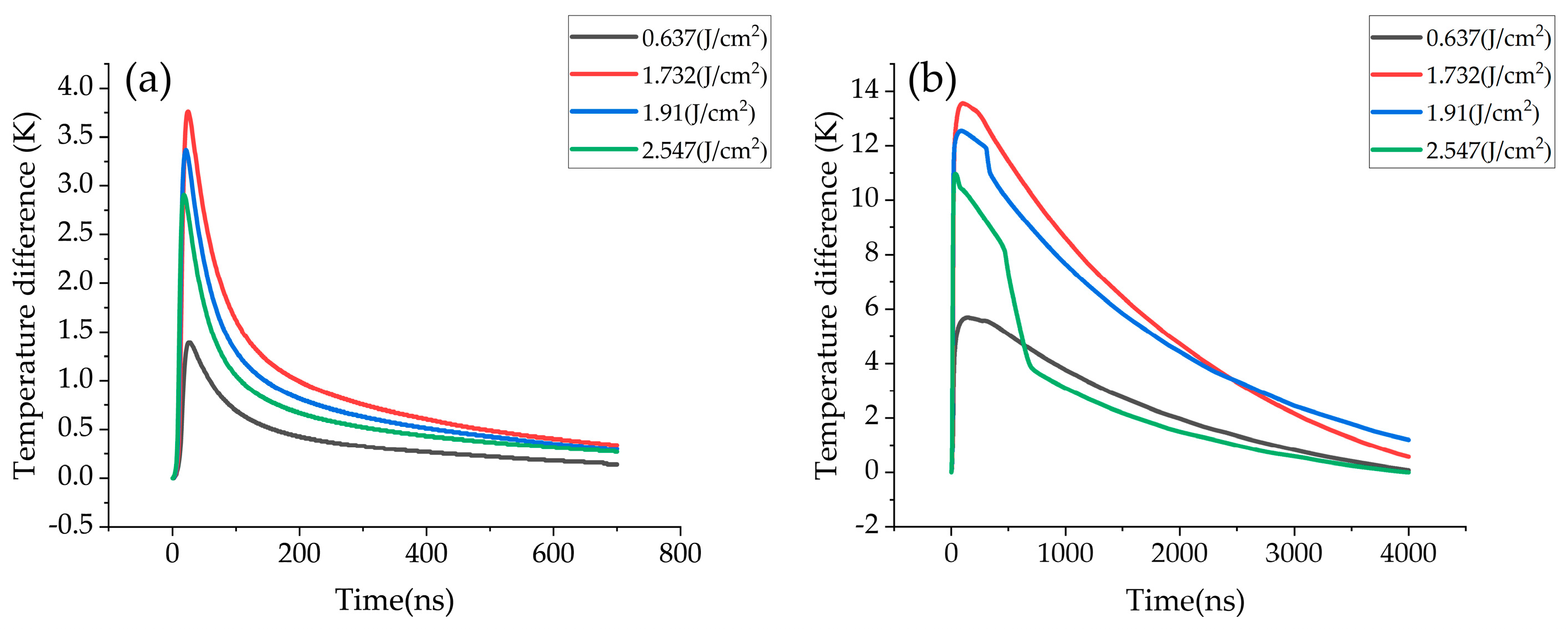
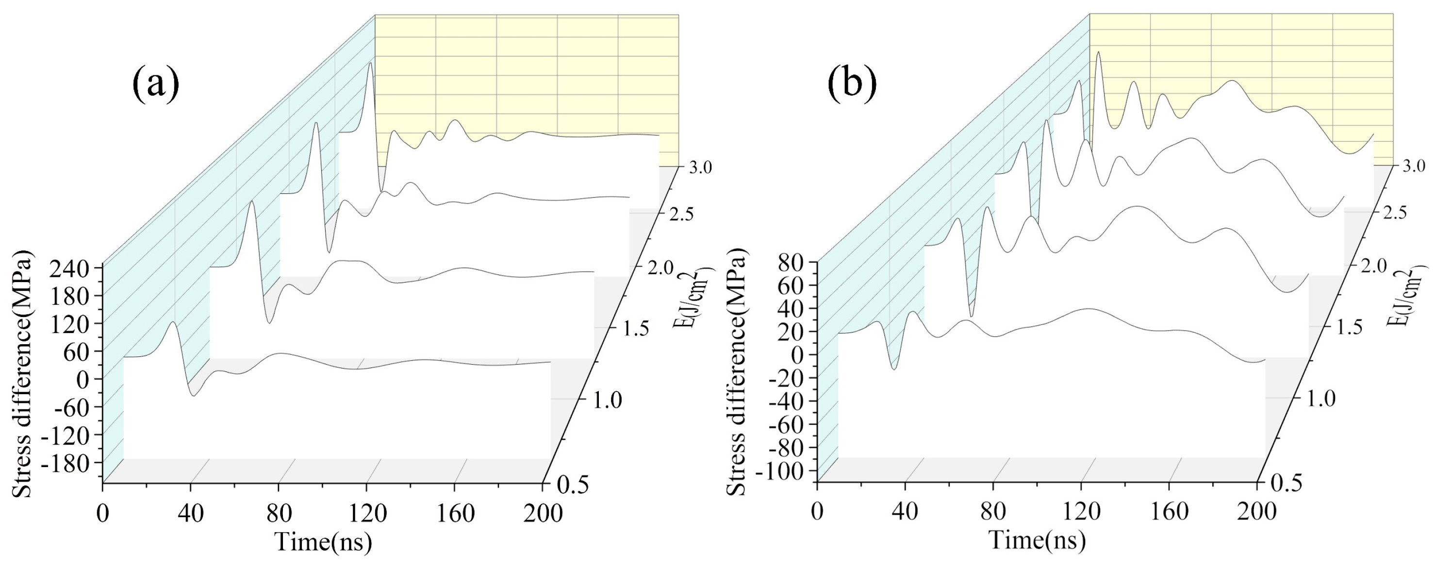
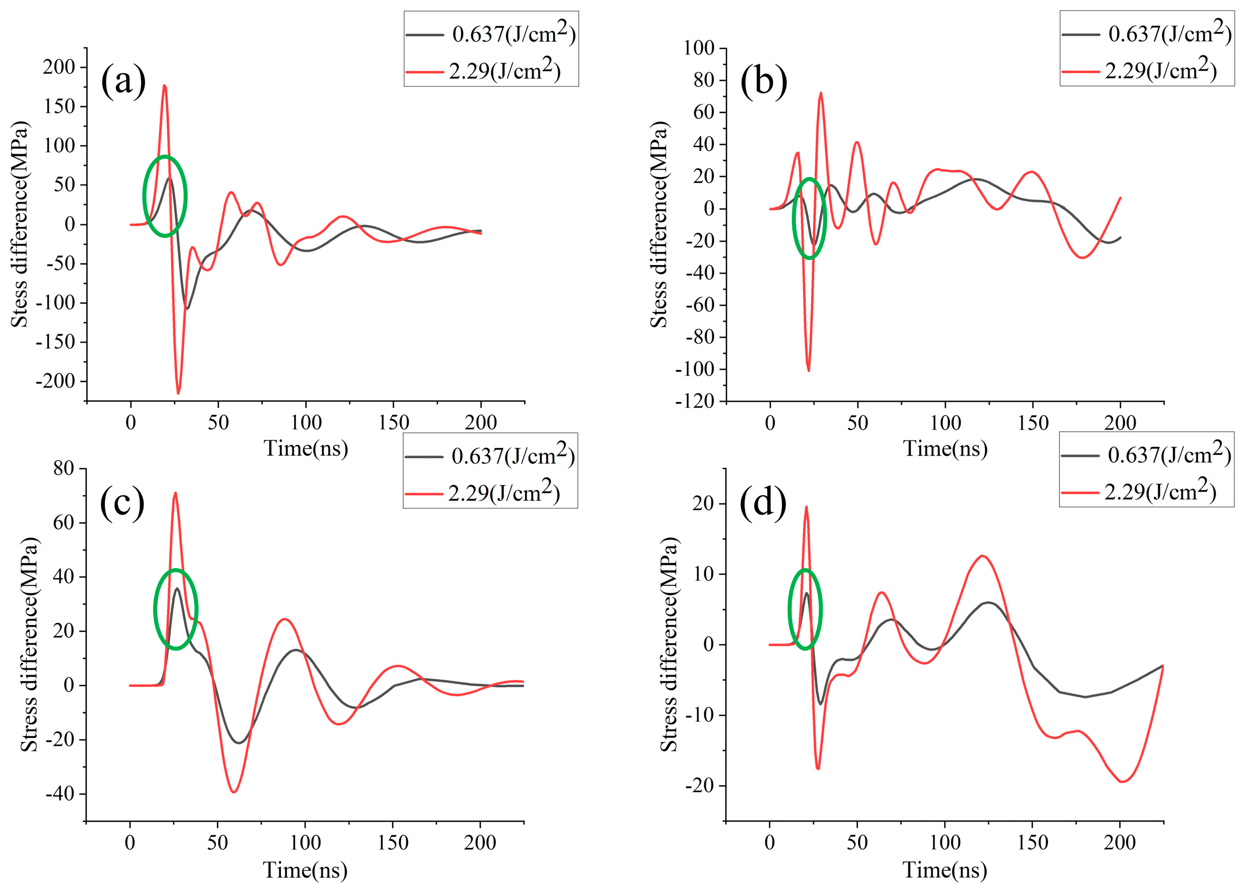
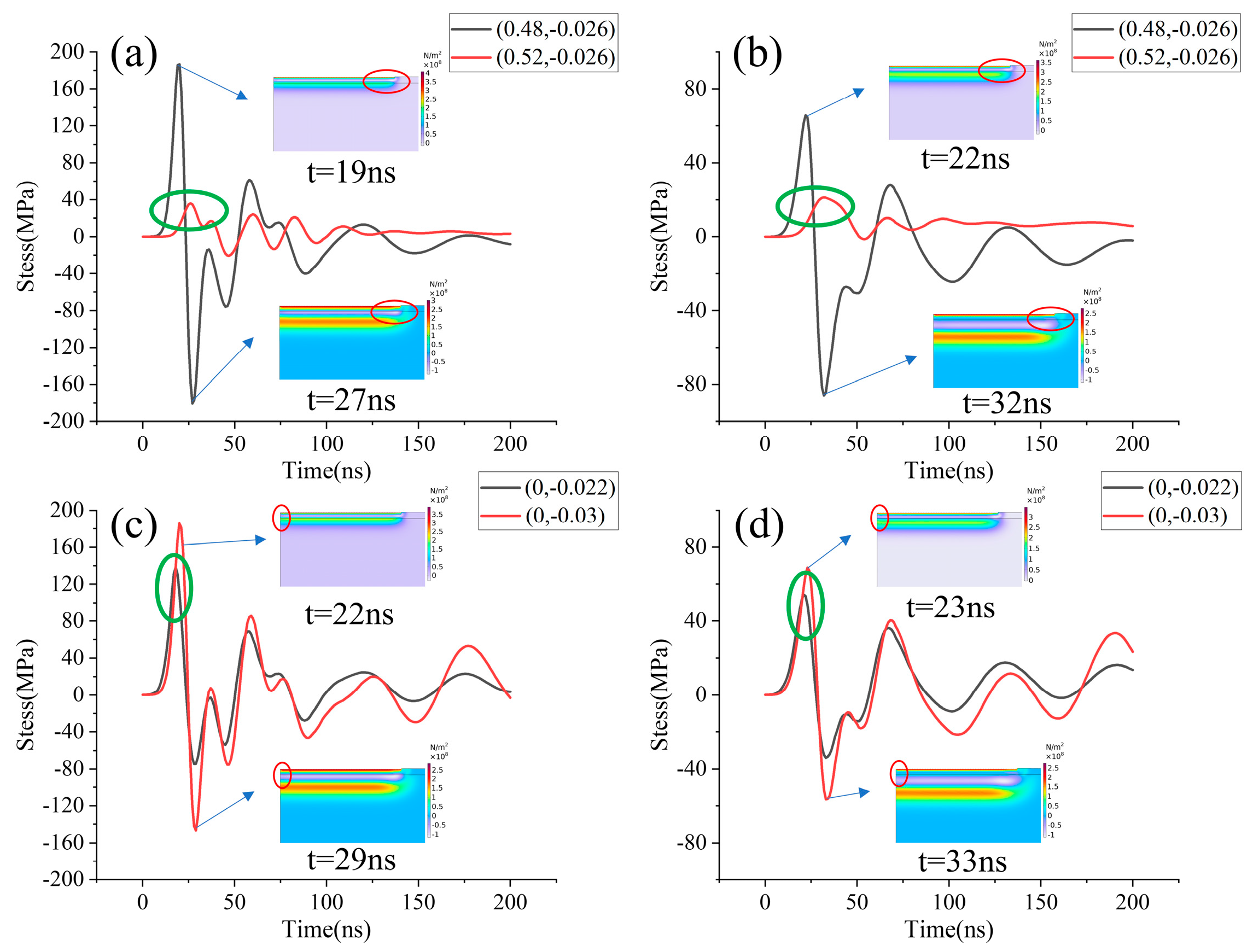
5.1. Simulation Results

Figure 4 shows the evolution of the material surface temperature with time during laser paint removal. Figure 4a–c shows the thermal distribution of the material at different times when the energy density is 2.3 J/cm2. Figure 4d shows the spatial distribution of the thermal radiation flux to the paint film at 12 ns. It is found that during laser paint removal, the material temperature rises rapidly and reaches a peak at 10 ns. The paint film’s subsequent gasification processes cause the material’s surface temperature to drop rapidly. Since the gasification rate of the paint film is related to temperature, the temperature slowly decreases after the laser pulse.
During laser paint removal, the absorption of laser energy by the material and the surface plume causes the temperature of the material to rise and generate a plasma shock on its surface. Figure 5 shows the evolution of the temperature difference over time between the paint film and the substrate ((0, −0.022) and (0, −0.03)) and between the paint films (0.48, −0.026) and (0.52, −0.026). Simulation research shows that the temperature difference between the paint film and the substrate is much smaller than the temperature difference between the paint films. Therefore, the difference in thermal stress between the paint film and the substrate is significantly smaller than between the paint films.
In addition, since we assumed there would be ideal contact between the paint film and the substrate, the stress difference between the paint films at the interface when the plasma shock propagated was equal to that between the substrates. According to Formulas (28) and (29), it is found that the stress difference between the film and the substrate is significantly smaller than the stress difference between the paint films. Therefore, the actual stress difference between the paint film and the substrate is significantly smaller than the actual stress difference between the paint films.
Figure 6 shows the changes in the maximum stress difference with laser fluence. When the laser fluence exceeds 0.66 J/cm2, the stress difference between the paint film and the substrate is higher than its adhesion strength. The paint film and substrate begin to separate. When the laser fluence is higher than 1.1 J/cm2, the stress difference between the paint films exceeds its fracture strength. The paint film begins to fracture.
In addition, plasma shock and thermal stress have different generation times, causing a discrepancy between the actual and thermal stress differences. Figure 6 shows that when the laser fluence is higher, the actual stress difference is almost equal to the thermal stress difference. Since the plasma shock force is significantly smaller than the thermal stress, the difference in thermal stress can instead be the actual stress difference. The primary mechanism for nanosecond laser paint removal is thermal and plasma shock.
Figure 7 shows that the actual stress difference between the paint films decays rapidly after the laser pulse. As the laser fluence increases, the relaxation of the actual stress difference between the paint film and the substrate after the end of the laser pulse becomes stronger and stronger, as shown in Figure 7. This relaxation is due to the reflection of the stress wave at the paint film and substrate interface.
Figure 8 shows the evolution of stress difference with time under different laser fluence. The generation time of the plasma shock and the thermal stress is different, resulting in a difference between the actual stress difference and the thermal stress difference. As the laser fluence increases, the distance between the thermal and the plasma stress peak between paint films increases, as shown in Figure 8a,b. As a result, the difference between the paint films’ thermal and actual stress becomes smaller, as shown in Figure 6b.
When the laser fluence is small, the distance between the peak of the thermal stress wave and the peak of the plasma shock wave is significant, resulting in a slight difference between the actual and thermal stress. As the laser fluence increases, the thermal stress waveform shifts to the left relative to the plasma waveform. There is a significant difference between the troughs of thermal stress waves and the peaks of plasma shock waves, as shown in Figure 8c,d. This significant difference increases the difference between thermal and actual stress as the laser fluence increases, as shown in Figure 6a.
The material temperature changes during laser paint removal are shown in Figure 4. Due to the rapid change in material temperature, thermal stress waves are generated inside the material and propagate outward. Figure 9 shows the evolution time of the thermal stress difference at different locations. From Figure 9, we found that the intensity of the thermal stress wave increases as the laser fluence increases. As a result, the difference in thermal stress increases with the increase in laser fluence. However, the longitudinal thermal stress wave speed increases, causing the (0.52, −0.026) and (0.48, −0.026) point waveforms to move relatively to the left, as shown in Figure 9a,b. The thermal stress difference between these two points fluctuates due to the relative displacement of the waveform to the left. As the laser fluence increases, the relative displacement of the waveform causes the maximum thermal stress difference to fluctuate, as shown in Figure 6b.
When stress waves propagate between the paint film and the substrate, relative displacement occurs between the stress waves due to the different speeds of the reflected and transmitted stress waves. As the laser fluence increases, the relative displacement between the stress waves changes the stress difference between point (0, −0.022) and point (0, −0.03). When the laser fluence is 2.3 J/cm2, the relative speed of the thermal stress wave at the paint film interface is faster. Therefore, the thermal stress wave at the (0, −0.022) point produces a relative displacement to the left, as shown in Figure 9c,d. This relative displacement causes the maximum thermal stress difference to decrease with the increasing laser fluence. Therefore, the maximum stress difference fluctuates with the increase in laser fluence, as shown in Figure 6a.

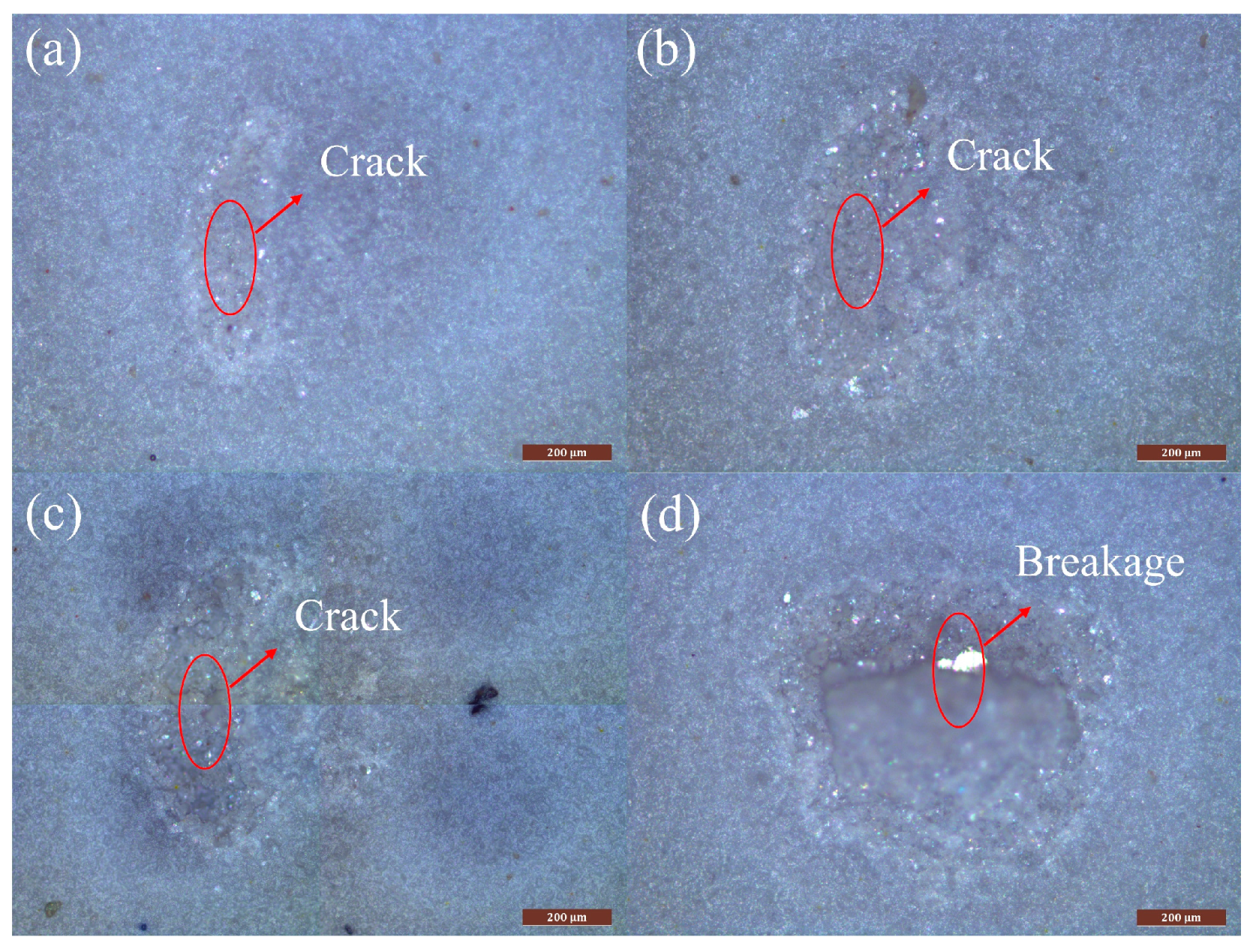
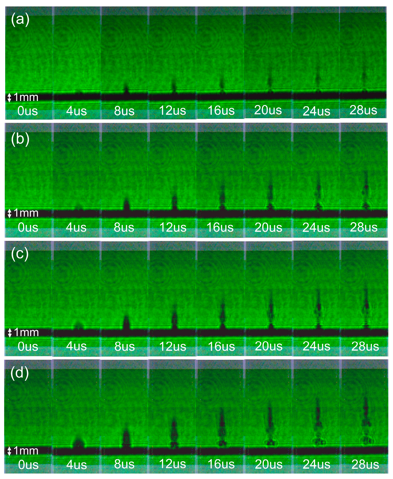
5.2. Experimental Results

According to the theoretical model, when the stress difference exceeds the adhesion strength between the paint film and the substrate, the paint film and substrate separate, as shown in Figure 10a. When the laser fluence exceeds the fracture threshold between the paint films at the point boundary, a fracture occurs between the paint films. However, when stress waves propagate between the paint films, they attenuate as the transmission distance increases. The fracture between paint films only occurs near the center of the light spot, and the fracture range of the paint film is very small, as shown in Figure 10d.
As the laser fluence increases, the paint removal effect increases. When the laser energy density is 1.2 J/cm2, the stress difference between the paint films is slight, and only the paint film in the center of the spot can be removed. The stress difference between the paint films increases as the laser energy density increases. When the laser fluence is 1.4 J/cm2, the paint film can be broken at the center and the boundary of the spot, as shown in Figure 11b.
However, with the increased laser fluence, the competition between thermal ablation and the stress stripping mechanism leads to contaminants on the substrate surface after laser paint removal. The temperature of the paint bottom increases and melts or pyrolyzes. If the stripping speed is fast, there are no residual pollutants. However, if the pyrolysis rate is fast, the pyrolysis products are deposited on the substrate and cause residual pollutants. Therefore, choosing the best laser paint removal parameters can improve the effect of laser paint removal.

5.3. Discussion

Figure 12 compares the experimental results of the laser ablation depth simulation and paint removal. During pulse laser paint removal, the ablation depth of the paint film increases with the increase in the laser energy density, as shown in Figure 12. There is a linear relationship between the pulsed laser fluence and ablation depth. The ablation depth of the nanosecond pulse laser is much smaller than the thickness of the paint film. By comparing simulation calculations and experimental results, it was found that the paint film stripping caused by thermal stress and plasma shock is the primary paint removal mechanism of the nanosecond pulse laser.
Figure 13 shows the surface plume evolution during laser paint removal. The rise in temperature of the paint film’s surface leads to ablation, while thermal stress and plasma shock cause the mechanical stripping of the paint film. After stripping, the paint film splashes outward due to inertia, as shown in Figure 13b.
When the laser fluence is small, the surface ablation plume and splashed paint film are smaller, resulting in a smaller stripping paint film area. When the laser fluence exceeds the paint removal threshold, as the laser fluence increases, the surface ablation plume and splashed paint film increase significantly, and the area where the paint film is stripped off increases significantly. Therefore, the nanosecond laser’s primary paint removal mechanism is mechanical stripping caused by plasma and thermal stress.
By comparing Figure 6b and Figure 9d, it is found that when the stress difference between the paint films exceeds the paint film fracture threshold, the paint film begins to fracture. When the laser fluence exceeds the paint film stripping threshold, the paint film quickly fractures and splashes outward, exposing a bright substrate, as shown in Figure 13b and Figure 11b. Therefore, the threshold for laser paint removal is approximately 1.4 J/cm2.

6. Conclusions

This paper establishes a thermal-mechanical-coupled laser paint removal model based on the heat conduction equation, Newton’s second law, and Fabbro’s theory. We used the COMSOL finite element software to simulate the model. By comparing the simulation and experimental results, we found that the thermal ablation depth of the nanosecond laser is relatively shallow. We found that the nanosecond pulse laser’s primary paint removal mechanism is the mechanical stripping caused by thermal stress and plasma shock. The threshold for laser paint removal is about 1.4 J/cm2.When the laser fluence is small, the surface ablation plume and splashed paint film are smaller, resulting in a smaller stripping paint film area. When the laser fluence exceeds the paint film stripping threshold, the paint film rapidly fractures and splashes outward, revealing a bright substrate. In addition, when the laser fluence is high, thermal stress is significantly greater than the plasma shock stress. Therefore, thermal stress can be used instead of actual stress when the laser fluence is high. Furthermore, the mutual superposition of stress waves occurs in the material due to the different generation times of plasma and thermal stress waves. This results in a discrepancy between the actual and thermal stress differences. The thermal stress difference causes the maximum actual stress difference to fluctuate.

Author Contributions

Conceptualization, Y.L. and W.Z.; methodology, G.J.; software, H.D.; validation, J.L., W.Z., and G.J.; formal analysis, Y.L.; investigation, G.J.; resources, W.Z.; data curation, J.L.; writing—original draft preparation, Y.L.; writing—review and editing, Y.L.; visualization, Y.L.; supervision, H.D.; project administration, W.Z.; funding acquisition, G.J. All authors have read and agreed to the published version of the manuscript.

Funding

This research was funded by the National Natural Science Foundation of China (U19A2077), the Changchun Science and Technology Development Plan (21ZY34), and the Jilin Provincial Department of Education Science and Technology Research (JJKH20230792KJ).

Institutional Review Board Statement

Not applicable.

Informed Consent Statement

Not applicable.

Data Availability Statement

The data supporting this study’s findings are available from the corresponding author upon reasonable request.

Conflicts of Interest

The authors declare that they have no known competing financial interest or personal relationship that could have appeared to influence the work reported in this paper.

References

  1. Zhu, G.; Wang, S.; Cheng, W.; Ren, Y.; Wen, D. Corrosion and wear performance of aircraft skin after laser cleaning. Opt. Laser Technol. 2020, 132, 106475. [Google Scholar] [CrossRef]
  2. Hu, C.; He, G.; Chen, J.; Fang, Z.; Yang, Z.; Zhang, Z. Research on Cleaning Mechanism of Anti-Erosion Coating Based on Thermal and Force Effects of Laser Shock. Coatings 2020, 10, 683. [Google Scholar] [CrossRef]
  3. Chen, G.X.; Kwee, T.J.; Tan, K.P.; Choo, Y.S.; Hong, M.H. Laser cleaning of steel for paint removal. Appl. Phys. A-Mater. Sci. Process 2010, 101, 249–253. [Google Scholar] [CrossRef]
  4. Liu, Y.; Liu, W.; Zhang, D.; Tian, Z.; Sun, X.; Wei, Z. Experimental investigations into cleaning mechanism of ship shell plant surface involved in dry laser cleaning by controlling laser power. Appl. Phys. A-Mater. Sci. Process 2020, 126, 1–17. [Google Scholar] [CrossRef]
  5. Abdul, M.K.A.; Jaafar, R.M.S.; Rahman, A.A.; Saidi, S.A. Identification of optimum operatives parameters for Pulse Nd:YAG laser in paint removal on different types of car coated substrate. Int. J. Edu. Res. 2014, 2, 47–64. [Google Scholar]
  6. Razab, M.K.A.A.; Jaafar, M.S.; Rahman, A.A.; Saidi, S.A. Estimation of Threshold Fluence, Absorption Coefficient and Thermal Loading of Car Coated Substrate in Laser Paint Removal. App. Mec. Mat. 2014, 554, 439–443. [Google Scholar] [CrossRef]
  7. Zhao, H.; Qiao, Y.; Du, X.; Wang, S.; Zhang, Q.; Zang, Y.; Liu, X. Laser cleaning performance and mechanism in stripping of Polyacrylate resin paint. Appl. Phys. A-Mater. Sci. Process 2020, 126, 360. [Google Scholar] [CrossRef]
  8. Brygo, F.; Dutouquet, C.; Le Guern, F.; Oltra, R.; Semerok, A.; Weulersse, J.M. Laser fluence, repetition rate and pulse duration effects on paint ablation. Appl. Surf. Sci. 2006, 252, 2131–2138. [Google Scholar] [CrossRef]
  9. Han, J.; Cui, X.; Wang, S.; Feng, G.; Deng, G.; Hu, R. Laser effects based optimal laser parameter identifications for paint removal from metal substrate at 1064 nm: A multi-pulse model. J. Mod. Opt. 2017, 64, 1947–1959. [Google Scholar] [CrossRef]
  10. Zheng, Z.; Wang, C.; Huang, G.; Feng, W.; Liu, D. Effect of Defocused Nanosecond Laser Paint Removal on Mild Steel Substrate in Ambient Atmosphere. Materials 2021, 14, 5969. [Google Scholar] [CrossRef]
  11. Zhang, D.; Xu, J.; Li, Z.; Li, K.; Wang, C.; Shan, D.; Guo, B. Removal mechanism of blue paint on aluminum alloy substrate during surface cleaning using nanosecond pulsed laser. Opt. Laser Technol. 2022, 149, 107882. [Google Scholar] [CrossRef]
  12. Roberts, D.E. Pulsed laser coating removal by detachment and ejection. Appl. Phys. A-Mater. Sci. Process 2004, 79, 1067–1070. [Google Scholar] [CrossRef]
  13. Kumar, A.; Sapp, M.; Vincelli, J.; Gupta, M.C. A study on laser cleaning and pulsed gas tungsten arc welding of Ti–3Al–2.5V alloy tubes. J. Mater. Process. Technol. 2010, 210, 64–71. [Google Scholar] [CrossRef]
  14. Tong, Y.; ShangGuan, J.; Ren, X.; Yuan, A.; Liu, J.; Lian, Z.; Hu, X.; Ma, J.; Yang, Z.; Wang, D. Surface quality of laser paint removal of marine steel: A comparative study using a Gaussian beam and a flat-top beam. Appl. Opt. 2022, 61, 2237–2246. [Google Scholar] [CrossRef]
  15. Sun, Q.; Zhou, J.Z.; Meng, X.K.; Yang, J.N.; Guo, Z.H.; Zhu, M.; Guo, S. Mechanism and threshold fluence of nanosecond pulsed laser paint removal. Rare Met. 2022, 41, 1022–1031. [Google Scholar] [CrossRef]
  16. Lu, Y.; Yang, L.; Wang, M.; Wang, Y. Simulation of nanosecond laser cleaning the paint based on the thermal stress. Optik 2021, 227, 165589. [Google Scholar] [CrossRef]
  17. Zhang, D.; Xu, J.; Li, Z.; Jin, Y.; Su, X.; Shan, D.; Guo, B. Removal mechanisms of nanosecond pulsed laser cleaning of blue and red polyurethane paint. Appl. Phys. A-Mater. Sci. Process 2022, 128, 170. [Google Scholar] [CrossRef]
  18. Dimitriou, V.; Kaselouris, E.; Orphanos, Y.; Bakarezos, M.; Vainos, N.; Tatarakis, M.; Papadogiannis, N.A. Three dimensional transient behavior of thin films surface under pulsed laser excitation. Appl. Phys. Lett. 2013, 103, 114104. [Google Scholar] [CrossRef]
  19. Gao, J.; Cao, Y.; Lu, L.; Hu, Z.; Wang, K.; Guo, F.; Yan, Y. Study on the interaction between nanosecond laser and 6061 aluminum alloy considering temperature dependence. J. Alloys Compd. 2022, 892, 162044. [Google Scholar] [CrossRef]
  20. Yue, L.; Wang, Z.; Li, L. Modeling and simulation of laser cleaning of tapered micro-slots with different temporal pulses. Opt. Laser Technol. 2013, 45, 533–539. [Google Scholar] [CrossRef]
  21. Stafe, M.; Negutu, C.; Popescu, I.M. Theoretical determination of the ablation rate of metals in multiple-nanosecond laser pulses irradiation regime. Appl. Surf. Sci. 2007, 253, 6353–6358. [Google Scholar] [CrossRef]
  22. Fang, R.; Zhang, D.; Li, Z.; Yang, F.; Li, L.; Tan, X.; Sun, M. Improved thermal model and its application in UV high-power pulsed laser ablation of metal target. Solid State Commun. 2008, 145, 556–560. [Google Scholar] [CrossRef]
  23. Zhang, W.; Yao, Y.L. Micro Scale Laser Shock Processing of Metallic Components. Manuf. Sci. Eng. 2002, 124, 369–378. [Google Scholar] [CrossRef]
  24. Bauerle, D. Laser Processing and Chemistry, 4th ed.; Springer: Heidelberg, Germany, 2011; p. 120. [Google Scholar]
  25. Fabbro, R.; Fournier, J.; Ballard, P.; Devaux, D.; Virmont, J. Physical study of laser-produced plasma in confined geometry. J. Appl. Phys. 1990, 68, 775–784. [Google Scholar] [CrossRef]
  26. Fabbro, R.; Peyre, P.; Berthe, L.; Scherpereel, X. Physics and applications of laser-shock processing. J. Laser Appl. 1998, 10, 265–279. [Google Scholar] [CrossRef]
  27. Xiong, Q.; Shimada, T.; Kitamura, T.; Li, Z. Atomic investigation of effects of coating and confinement layer on laser shock peening. Opt. Laser Technol. 2020, 131, 106409. [Google Scholar] [CrossRef]
  28. Liao, Y.; Ye, C.; Cheng, G.J. A review: Warm laser shock peening and related laser processing technique. Opt. Laser Technol. 2016, 78, 15–24. [Google Scholar] [CrossRef]
  29. Tang, W.H. Shockwave Physics; China Science Publishing: Beijing, China, 2011; pp. 204–207. [Google Scholar]
  30. Zhu, Z.M.; Gong, X.F.; Du, G.H. Acoustic Fundamentals; Nanjing University Press: Nanjing, China, 2012; pp. 132–134. [Google Scholar]
  31. Li, Y.; Li, J.; Dong, H.; Zhang, W.; Jin, G. Mechanism of paint removal by nanosecond pulsed laser plasma shock: Simulation and experiment. Appl. Opt. 2023, 62, 2855–2861. [Google Scholar] [CrossRef]
  32. Wei, H.; Xia, J.; Zhou, W.; Zhou, L.; Hussain, G.; Li, Q.; Ostrikov, K. Adhesion and cohesion of epoxy-based industrial composite coatings. Compos. Pt. B-Eng. 2020, 193, 108035. [Google Scholar] [CrossRef]
  33. Papadopoulos, K.; Tserpes, K. Analytical and Numerical Modeling of Stress Field and Fracture in Aluminum/Epoxy Interface Subjected to Laser Shock Wave: Application to Paint Stripping. Materials 2022, 15, 3423. [Google Scholar] [CrossRef]
  34. Millett, J.C.F.; Bourne, N.K.; Barnes, N.R. The behavior of an epoxy resin under one-dimensional shock loading. J. Appl. Phys. 2002, 92, 6590–6594. [Google Scholar] [CrossRef]
  35. Isbell, W.M. Shock Waves: Measuring the Dynamic Response of Materials; Imperial College Press: London, UK, 2005; pp. 214–219. [Google Scholar]
  36. Zou, W.F.; Xie, Y.M.; Xiao, X.; Zeng, X.; Zeng, X.Z.; Luo, Y. Application of thermal stress model to paint removal by Q-switched Nd:YAG laser. Chin. Phys. B 2014, 23, 433–438. [Google Scholar] [CrossRef]
  37. Esfahani, J.A.; Sousa, A.C. Ignition of epoxy by a high radiation source. A numerical study. Int. J. Therm. Sci. 1999, 38, 315–323. [Google Scholar] [CrossRef]
  38. Lascano, D.; Lerma-Canto, A.; Fombuena, V.; Balart, R.; Montanes, N.; Quiles-Carrillo, L. Kinetic analysis of the curing process of biobased epoxy resin from epoxidized linseed oil by dynamic differential scanning calorimetry. Polymers 2021, 13, 1279. [Google Scholar] [CrossRef]
Figure 1. Experimental schematic diagram of pulsed laser paint removal.
Photonics 11 00025 g001
Figure 2. Flowchart of simulation steps.
Photonics 11 00025 g002
Figure 3. Mesh division of 2D axisymmetric finite element model: (a) Nanosecond laser paint removal principle (b) Finite element meshing.
Photonics 11 00025 g003
Figure 4. Evolution of material surface temperature with time during nanosecond pulse laser paint removal: (a) t = 10 ns, (b) t = 50 ns, (c) t = 200 ns, (d) t = 12 ns.
Photonics 11 00025 g004
Figure 5. Evolution of material temperature difference with time: (a) temperature difference between the paint film and substrate, (b) temperature difference between the paint films.
Photonics 11 00025 g005
Figure 6. The changes in maximum stress difference with laser fluence: (a) maximum stress difference between the paint film and substrate ((0, −0.022) and (0, −0.03)) and (b) maximum stress difference between the paint films ((0.48, −0.026) and (0.52, −0.026)).
Photonics 11 00025 g006
Figure 7. The evolution of the actual stress difference with time under different laser fluences: (a) the actual stress difference between the paint films, and (b) the actual stress difference between the paint film and the substrate.
Photonics 11 00025 g007
Figure 8. The evolution of stress difference with time under different laser fluence: (a) the thermal stress difference between paint films, (b) the plasma shock stress difference between paint films, (c) the thermal stress difference between the paint film and substrate, and (d) the plasma shock stress difference between paint film and substrate.
Photonics 11 00025 g008
Figure 9. Evolution of thermal stress difference with time at different locations: (a) E = 2.3 J/cm2, (b) E = 0.636 J/cm2, (c) E = 2.3 J/cm2, (d) E = 0.636 J/cm2.
Photonics 11 00025 g009
Figure 10. Paint removal effect changes with laser fluence: (a) E = 0.72 J/cm2; (b) E = 0.83 J/cm2; (c) E = 0.96 J/cm2; (d) E = 1.12 J/cm2.
Photonics 11 00025 g010
Figure 11. Paint removal effect changes with laser fluence: (a) E = 1.2 J/cm2; (b) E = 1.4 J/cm2; (c) E = 1.78 J/cm2; (d) E = 2 J/cm2.
Photonics 11 00025 g011
Figure 12. The laser ablation depth simulation and experimental results of laser paint removal are compared.
Photonics 11 00025 g012
Figure 13. Plume evolution on the surface of the paint film. (a) E = 1.2 J/cm2; (b) E = 1.4 J/cm2; (c) E = 1.78 J/cm2; (d) E = 2 J/cm2.
Photonics 11 00025 g013
Table 1. Material parameters of aluminum alloys and paints.
PropertiesPaintAluminum Alloy
Density ρ (kg/m3)1700 [33]2736 − 9.4 × 10⁻³ T − 6.04 × 10⁻⁴ T2 + 8.99 × 10⁻⁷ T3 − 5.41 × 10⁻¹⁰ T4
Sound speed V (m/s)2580 [34]5341 [35]
Thermal conductivity k (W/(m·K))0.2 [36]165 − 0.06 T + 3.97 × 10⁻⁴ T2 − 3.63 × 10⁻⁷ T3
Specific heat capacity Cp (J/kg·K)1800 [37]−5.6 + 6.73 T − 1.54 × 10⁻² T2 + 1.6 × 10⁻⁵ T3 − 6.2 × 10⁻⁹ T4
Thermal expansion coefficient α (1/K)6 × 10−51.32 × 10−5 + 8.31 × 10⁻⁸ T − 2.91 × 10⁻¹⁰ T2 + 4.99 × 10⁻¹³ T3 − 3.13 × 10⁻¹⁶ T4
Young’s modulus E (GPa)4.16 [33]7.66 × 10¹⁰ + 2,007,396 T − 186,458 T2 + 419 T3 − 0.349 T4
Poisson’s ratio ν (1)0.3 [33]0.329 + 3.75 × 10⁻⁶ T + 2.21 × 10⁻⁷ T2 − 6.565×10⁻¹⁰ T3 + 4.21 × 10⁻¹³ T4 + 3.17 × 10⁻¹⁶ T5
Plume expansion velocity νp (m/s)340 [20]
The absorption coefficient of the plume κp (1/m)2.5 × 104 [12]
Laser absorption rate of paint film A (1)0.8
Latent heat of gasification ΔHv (J/kg)2.05 × 105 [38]
Disclaimer/Publisher’s Note: The statements, opinions and data contained in all publications are solely those of the individual author(s) and contributor(s) and not of MDPI and/or the editor(s). MDPI and/or the editor(s) disclaim responsibility for any injury to people or property resulting from any ideas, methods, instructions or products referred to in the content.

