Abstract
A compact OCT device and a method for image reconstruction are described. The proposed algorithm contains a novel procedure for motion artifact suppression based on a correction of the phase of the original interferometric signal due to the mutual correlation of adjacent A-scans. This procedure corrects distortions caused by unwanted displacements of the probe relative to the object in real time at a speed of up to 3 mm/s and an image acquisition rate of 20 B-scans per second. All processing is performed in real time using only the CPU, allowing the device to be controlled from a consumer-grade laptop or compact PC without the need for a discrete GPU. Due to its compact size, the device can be used in the conditions of an ENT examination room or operating room and can be freely moved to another room without the help of additional personnel, if necessary.
1. Introduction
This paper discusses problems associated with the creation of an otoscopic optical coherence tomography system. This system is a prototype for a new medical diagnostic device designed to study the tympanic cavity of the human ear in vivo. The aim is to obtain a 3D image of the eardrum.
This system is based on the spectral domain optical coherence tomography (SDOCT) method [1,2]. The main application area of SDOCT is visualization of the internal structure of near-surface biological tissues. SDOCT uses low-power broadband optical probing radiation in the near-infrared range. The radiation is scattered on the inhomogeneities of the tissues being studied. The backscattered part of the radiation is recorded interferometrically. The optical spectrum of the interference signal is then mathematically processed to synthesize an image that corresponds to the spatial distribution of backscattering inhomogeneities inside the object under study. The low power of the probing radiation ensures the non-invasiveness of a study.
A specific feature of the otoscopic application of SDOCT is the large range (>4 mm) and the possible high speed of the mutual movement of the probe and the object when searching for a zone of interest. The large mutual velocity of movement can be the cause of “mirror” artifacts on the SDOCT image. Here, we propose and describe a method for processing SDOCT signals to suppress artifacts of this kind.
2. Scheme and Operating Procedure for the SDOCT Otoscopic System
The photo image of the base block and the handheld probe of our SDOCT otoscopic system are shown in Figure 1.
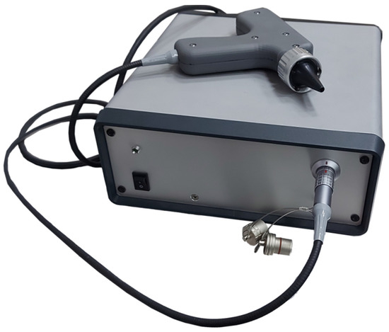
Figure 1.
The base block and the handheld probe of the SDOCT otoscopic system.
A schematic diagram for the SDOCT otoscopic system is shown in Figure 2.
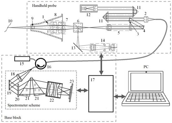
Figure 2.
A schematic diagram showing the SDOCT otoscopic system. 1—LED backlight; 2—collimating lens; 3—partially transparent mirror; 4—scanning mirror; 5—focusing element; 6—dichroic mirror; 7—magnifier; 8—standard ear speculum; 9—exit window; 10—surface of the eardrum; 11—prism; 12—reference arm reflector with modulated length; 13—mirror; 14—USB video camera assembly; 15—probing radiation source; 16—fiber circulator; 17—data acquisition and control module; 18—collimating element with fiber-optic interface; 19—mirror; 20—diffraction grating; 21—components of a composite prism corrector; 22—focusing element; 23—line scan sensor.
The interferometric circuit and the lateral scan system based on a microelectromechanical mirror are placed inside the handheld probe. In addition, the video camera (true color HD 1280 × 720 1/4‴ 30 fps CCD array from Shenzhen HQCAM electronic Technology Co., Ltd, Shenzhen, China) with a USB 2.0 interface and home-built optics and LED (eight pcs 0402 size diodes in two groups of different temperature colors) backlight are located inside the handheld probe. This camera performs auxiliary and additional functions. The LED backlight and output optical elements are arranged inside a standard disposable ear speculum.
The central wavelength of the probing radiation in this SDOCT system is ~1.3 μm (SLD1021, Thorlabs, Newton, NJ, USA).
The probe [3] provides a transverse resolution of ~20 μm. It is connected with an electro-optical cable to the base block of the SDOCT system, in which there is a power supply, a source of probing radiation, a data acquisition and control module [4,5], and a spectrometer [6,7]. The spectrometer is based on a T-1200-1310 (LightSmyth, Eugene, OR, USA) grating with a line density of 1200 lines mm−1 and has a recording bandwidth of 80 nm. Equidistancy correction of the registration of spectral components is carried out using a combined corrector [8] based on custom-made elements (Nanyang Jingliang Optical Technology Corp., Nanyang, China). The optical spectrum is recorded using an SU-512LDB-1.7T1 linear photodetector array (Goodrich, Charlotte, NC, USA). The bandwidth-limited spatial resolution of the base unit is 11 mm; the maximum range of imaging in depth in one frame is 3.2 mm. The data acquisition rate of the spectrometer is about 20,000 A-scans/s. The whole imaging area size for the used SDOCT is ~4.5 × 4.5 × 4.5 mm3 obtained in 512 × 512 × 512 voxels of OCT data.
Processing, control, and visualization functions are performed using a standard personal computer, with which the base block of the SDOCT system is connected using a USB 2.0 interface.
The procedure for the user of this SDOCT otoscopic system is as follows. First, the user must find an area of interest. To do this, the user moves the disposable ear speculum, fixed at the distal end of the hand probe, along the external auditory canal of the patient. At the same time, the SDOCT system continuously synthesizes and visualizes the corresponding central tomographic slice in real time. Having found the area of interest, the user turns on the 3D scanning mode, trying to keep the probe motionless. The SDOCT system synthesizes and renders a sequence of tomographic slices that together make up a 3D voxel image.
3. Real-Time Visualization Routine for the Region-of-Interest Search
The procedure used to search for an area of interest is a rather complicated and very important stage. In the search mode, the user should be continuously provided with visual information about the current position of the probe with minimal delay. This is important to ensure the interactivity of user actions.
This task should be solved using the computing power of an embedded mobile CPU for image synthesis and visualization procedures. This is necessary for further modification of the otoscopic SDOCT system in a compact form with an embedded computer.
3.1. Using the Built-In Video Camera
The user can control the current position of the probe from images that the built-in video camera broadcasts in real time. The optical elements of the probe are configured in such a way that the focus position of the video camera coincides with the middle of the SDOCT imaging volume. An example video image of the eardrum captured with a built-in video camera is shown as a single frame in Figure 3.
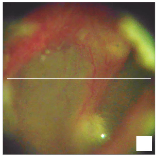
Figure 3.
A frame showing a real-time video image of the eardrum. Scale bar 0.5 mm.
The horizontal line in the video image indicates the position of a current tomographic slice.
The presence of the built-in video camera additionally makes it possible to use this SDOCT system as a standard video otoscope.
3.2. Real-Time Methods for SDOCT Image Synthesis
Practice shows that video visualization is not enough to accurately determine and stabilize the desired position of the probe. To find the area of interest and hold the probe still, the user must see the image of the current tomographic slice in real time.
Let us consider several methods for synthesizing SDOCT images.
In our SDOCT system, a line scan sensor registers the result of interference between reference radiation and radiation backscattered from inhomogeneities in the object. The sequence of such data (sources of A-scans) can be represented as the sum of autocorrelation and cross-correlation components [9] in the form:
where is the current number of the A-scan in a continuous sequence since the start of the scanning, is the optical difference between the path length of the reference and scattered radiation, is the speed of light, is the angular frequency of optical radiation, and is the remainder of the Euclidean division . The additional phase shift is the result of the modulation of the reference radiation path length, which is used in the interferometric scheme in Figure 2.
The autocorrelation component can be considered constant for all , i.e., . Therefore, the calculation for the backscattering index along the coordinate can be obtained in the form of the Fourier transform [1] from the function
The raw data for the B-scan (2D SDOCT image) is represented as a two-dimensional array with elements . The index is the corresponding element number of the linear scanning sensor, or, in other words, the number of the corresponding spectral component of the interference result. Index is the number of the A-scan in the B-scan, which corresponds to the horizontal coordinate in the 2D SDOCT image. If the B-scan is made up of A-scans, then the autocorrelation component can be calculated as:
In our opinion, this method for isolating the autocorrelation component is the most effective. Compared to other methods [9,10,11,12,13], it does not require additional measurements or complex calculations, relies on a large amount of data, takes into account current factors affecting the shape of the autocorrelation component (such as the spectral density of the probing radiation and the sensitivity of the linear scanning sensor) and their changes.
Then, the simplest variant of SDOCT image synthesis can be represented with the following transformations:
In Equation (4), is the number of elements in the linear scan sensor (samples in the A-scan). Therefore, in Equations (3)–(5), , , and .
In Equation (3), the multiplier is designed to compensate for the unevenness in the spectral density of the probing radiation and the unevenness in the spectral sensitivity of the linear scanning sensor. An example of possible values for the multiplier is shown in Figure 4.
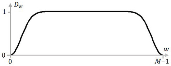
Figure 4.
An example of the multiplier .
Note, that Dw is a subject of empiric matching, so it was not expressed analytically. The shape of Dw corrects the impact of uneven sensitivity of photocells in an array, incomplete decay in the spectral intensity of radiation at the edges of the spectral recording range, etc.
Figure 5 shows the result of such a calculation when scanning a test object in the form of a matte silicone film ~0.3 mm thick glued to a rigid base with a double-sided adhesive tape ~1 mm thick.
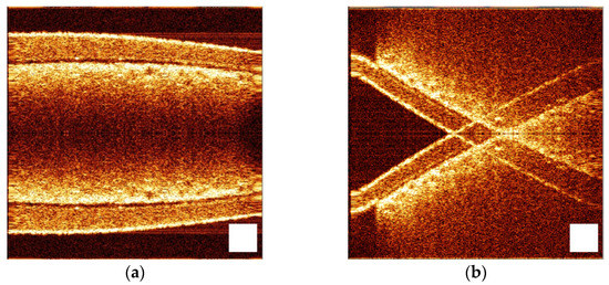
Figure 5.
Result of SDOCT image synthesis using transformations (3)–(5) when the surface of the test object is orthogonal to the direction of the probing beam (a) and not orthogonal (b). The images were obtained for the same phantom (silicone film on a sticky tape) tilted to the probing wave at different angles. Scale bar 0.5 mm.
At the top of Figure 5a, we can see an OCT image of a silicone film. Below is located a sticky tape, the lower border of which is not visible because of strong scattering—it is not transparent enough.
The lower half of the image is a “mirror” reflection of the upper one. This is a typical “mirror” artifact, which is a consequence of the Hermitian features of the Fourier image [9]. It has almost no effect on the SDOCT imaging of skin, mucous membranes, serous tissues, and even for ophthalmic systems. For example, one can simply not display (crop) the lower half of the image in this case (Figure 5a). However, the “mirror” artifact becomes a big problem for the otoscopic SDOCT system. The fact is that the tympanic membrane is not located orthogonally relative to the direction of the external auditory canal, i.e., relative to the main direction of the probing beam. This situation is illustrated in Figure 5b.
Here, the surface of the same test object is largely not orthogonal to the direction of the probing beam. The situation is complicated by the fact that, when moving the probe along the direction of the probing beam, the “mirror” artifacts move in the opposite direction relative to the main components of the image. This greatly hinders the search for the desired area.
It also should be borne in mind that in the otoscopic SDOCT system, the largest part of the visualized volume is airspace. Thus, the scattering signal does not attenuate strongly enough along the sensing direction. As a result, the recorded signal often exceeds the range of the recorded depth determined using the spectral resolution of the receiving node. This provokes a violation of the Nyquist–Shannon sampling theorem conditions [14,15,16] and leads to the repeated appearance of an object in the visualization area during the longitudinal movement of the probe.
Thus, the otoscopic SDOCT system requires a relatively large depth of visualization and effective methods for suppressing “mirror” artifacts. To achieve this, it is possible to use the modulation of the reference wave path length with the method described in [17]. This variant of SDOCT image synthesis can be represented as the following transformations:
where , , and .
where , , , and .
In Equation (7), the multiplier allows Fourier filtering of coherent interference and the autocorrelation component. An example of possible values for the multiplier is shown in Figure 6.
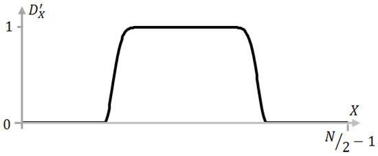
Figure 6.
An example of the multiplier .
Note that D′x and Dw are subject to empiric matching, so they were not expressed analytically. The shape of D′x depends on the technical features of the specific instance of the SDOCT system in use and corrects the impact of radio-technical noises and spurious (induced) signals, suppressing some spurious reflection responses in the optical circuit.
Figure 7 shows the result of SDOCT image synthesis using transformations (6)–(9).
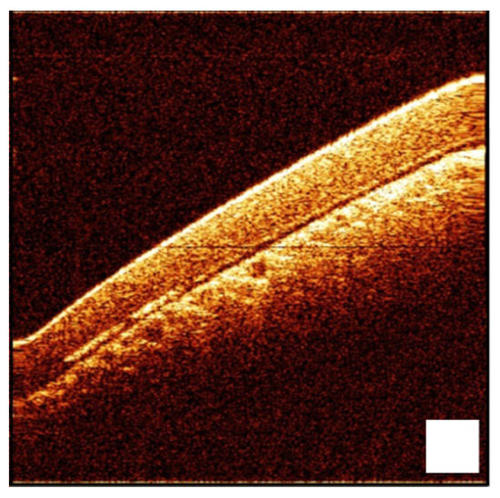
Figure 7.
Result of SDOCT image synthesis using transformations (6)–(9). The image was obtained for a silicone film phantom located on a sticky tape tilted to the probing wave. Scale bar 0.5 mm.
Thus, it is possible to achieve the suppression of “mirror” artifacts.
Since, for this SDOCT system, and , the discrete Fourier transform in the Formulas (4), (6) and (8) can be replaced with the fast Fourier transform () and the transformation in Formula (7) can be replaced with the inverse fast Fourier transform () [18,19].
3.3. Method for the Suppression of “Mirror” Artifacts
In the process of searching for the area of interest, the probe may be moved razer fast along the direction of the probing beam. In such conditions, Equation (1) may lose its validity since becomes dependent on the speed of the probe movement due to the Doppler effect [20]. As a result, in the image synthesized using transformations (6)–(9), a partial appearance of “mirror” artifacts and suppression of the true image occur.
To solve this problem, we propose a novel method that uses a partial mutual correlation between neighboring A-scans due to their partial mutual overlap. The mutual overlap of neighboring A-scans is illustrated in Figure 8.
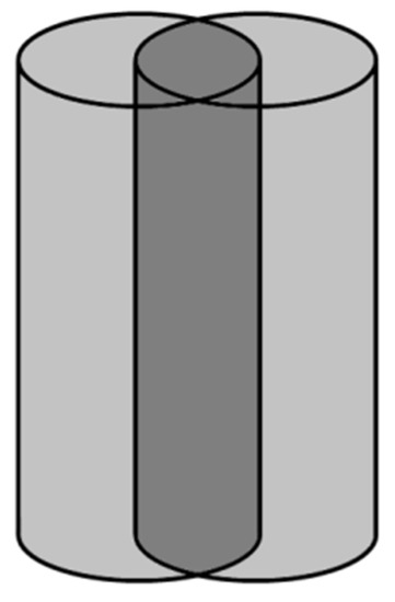
Figure 8.
Illustration showing partial mutual overlap of neighboring A-scans.
This method offers a way to separate the true and “mirror” components of a tomographic image, taking into account the fact that when the probe moves, the phase shift in these components occurs in opposite directions. This makes it possible to adjust the phase of corresponding image elements in opposite ways. In the Fourier domain, the “mirror” components of the tomogram can be stabilized in the region of negative spatial frequencies and then suppressed using the Hilbert transform [21] and Fourier filtering.
At the first stage of transformations, we calculate the Fourier image of the cross-correlation component of the source signal in the form:
where , , and .
This is followed by the calculation of complex values to determine the phase difference between adjacent A-scans:
where , , and is the result of complex conjugation of the value of .
The result of the transformation (11) can be used to calculate binary coefficients, which are intended for marking true and “mirror” elements of the tomographic image.
where and . The procedures (12) describe a criterion that determines whether a given image element is more true or “mirror”.
Then, the corresponding phase differences and their cumulative values can be calculated as:
where . The transformations (13) take into account the phase difference determined using the modulation of the reference radiation path length.
The obtained values can be used for the corresponding phase correction in the form of:
where and .
The following sequence of Fourier transforms is necessary to implement the Hilbert transform and Fourier filtering:
where , , and .
where , , , and .
Here, the Hilbert transformation is performed due to the fact that the transformation (16) is carried out for N samples and the transformations (17)–(19) for N/2 samples. Thus, the formation of an analytical signal is carried out, in which the mirror components are suppressed. In addition, this sequence of forward and inverse Fourier transforms is performed in order to use the filtering multipliers and in the corresponding Fourier domain. The logarithm of the module for the final transformation in Equation (19) is necessary to convert complex values into actual values for the brightness of the tomographic image corresponding to the scale in decibels.
3.4. Comparative Evaluation of the Suppression of “Mirror” Artifacts
An experiment was performed to evaluate the effectiveness of transformations (10)–(19). The results are shown in Figure 9. The source raw data were recorded at different speeds of longitudinal movement of the test object. Then they were subjected to transformations (6)–(9) and (10)–(19).
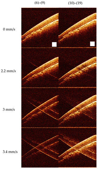
Figure 9.
The results of transformations (6)–(9) and (10)–(19) at different speeds of the longitudinal movement of the test object. The images were obtained for a silicone film phantom located on sticky tape tilted to the probing wave and shifted with different velocities in the probing direction. Scale bar 0.5 mm.
The speed of movement of the test object was estimated as follows. The depth of the visualized volume was measured by registering reflections from a test object mounted on a platform with a micrometer and moved using this micrometer along the direction of the probing beam. The test object was attached to the center of the acoustic speaker membrane. This membrane carried out longitudinal sinusoidal oscillations. This SDOCT system recorded and visualized the corresponding sequence of B-scans. The frequency and amplitude of the membrane oscillations were set using a laboratory generator. Thus, knowing the amplitude of the membrane vibrations and the frequency of B-scans, it is possible to match the instantaneous speed of movement of the test object with sufficient accuracy to each B-scan.
The experiment demonstrated that the proposed method successfully suppressed “mirror” artifacts in a certain range of longitudinal movement speeds with minimal distortion in the true image. The method for SDOCT image synthesis proved to be useful at the stage of searching for an area of interest.
4. The Result of 3D Visualization of the Eardrum
The SDOCT image synthesis procedure using transformations (10)–(19) does not distort the true image at the stage of the 3D scanning process. At the same time, the structure of mathematical manipulations in the proposed method allows them to be used within the framework of the asynchronous parallel computing method described in [22], which provides high-quality 3D visualization in real time. Figure 10 shows an example of the application of this SDOCT image synthesis method as part of the otoscopic SDOCT system. The data for Figure 10 were taken in a seated position, holding the probe in hand without any additional mounting accessories.
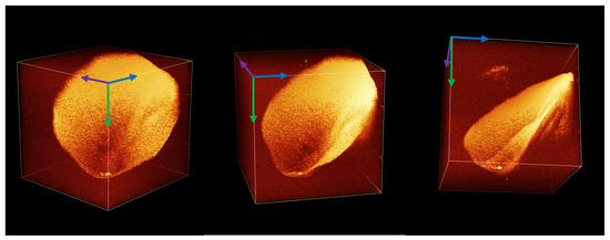
Figure 10.
A voxel 3D image of the human eardrum obtained with the otoscopic SDOCT system.
5. Discussion
The proposed SDOCT system shows a high rate of data acquisition—12 s for a 3D dataset. The reconstructed tomography 3D data contains a 512 × 521 × 512 voxel array, corresponding to a 4.5 × 4.5 × 4.5 mm volume of the medium under investigation (in the air). All the data are reconstructed online synchronously with image acquisition. All image distortions caused by both coherent noises and errors due to physiologic displacements (tremor, pulse, respiration, small random displacements) are also corrected in real time while the image is calculated.
The imperfection of the device and its software, which the operator has to put up with, is the insufficient effectiveness for suppressing the “mirror” component (one of the types of coherent artifacts that manifests itself in the form of a symmetrical structure relative to the center of the image) of the signal at a relatively high speed of movement of the probe relative to the object under study.
This is a fundamental limitation determined by the effective bandwidth of the received signal. However, the manifestations of distortions arising from the violation of the phase relationships between the signal components at speeds above the critical ones (in the described device and using the proposed calculation method—3 mm/s) do not affect the ability to navigate and search for the target area, subject to minimal training and experience of the operator.
The time for obtaining a full 3D image in the described device (12 s) is short enough to allow the OCT scanning procedure to be performed under the conditions of a standard otoscopic examination without the use of anesthesia or special restraints. The light abutment of the ear speculum to the wall of the external auditory canal, in combination with the fixation of the operator’s hand on the external bones of the skull, provides a sufficient level of stability in the relative position of the probe and the object under study so that the proposed algorithm effectively suppresses the effect of residual displacements. This is convincingly shown in Figure 10, which was obtained in a sitting position, holding the probe in hand without any additional fixing devices. Moreover, the compact size of the device makes it possible to use it in the conditions of an ENT examination room or operating room/dressing room and freely move it, if necessary, to another room without the help of additional personnel.
Thus, the presented device can significantly expand the diagnostic potential of the ENT cabinet with the introduction of an easy-to-use, highly sensitive instrument that allows diagnosing otitis media with effusion [3,23,24] (with an accuracy that exceeds currently used methods, without the involvement of additional specialists), as well as biofilms [25] and other pathologies in the middle ear [26,27], including tympanic membrane retractions, thickening, and thinning [28].
In this regard, it should be noted that the use of optimization of computing processes and compact elements of the optical fiber circuit made it possible to implement a device that can be transported effortlessly by one person and occupies minimum working space, which is important both for organizing a workplace in an ENT office and for the mobility of the device as a whole. This favorably distinguishes the described device from a number of known analogs mentioned in [29,30,31,32], without affecting its diagnostic potential. At the same time, it should be noted that there are some reports on compact devices [26,33,34]. The presented device has all the advantages of a compact device, but it allows for obtaining 3D images. This, in our opinion, significantly increases its sensitivity in terms of the detection of transparent effusions [35].
It should be noted that the use of OCT for otoscopic diagnostics has some limitations. Since patient safety is achieved using standard disposable specula supplied in sterile packaging, all the contraindications for otoscopic examination using standard ear speculum are also contraindications for OCT diagnostics using the presented device. For the rest, the device may be used in a wide range of clinical environments. Since the speculum can be inserted into the probe tip directly from the packaging, which eliminates the need for the clinician to come into contact with its surface, the OCT examination may be provided in any ENT office or temporal office (including screening employees of the enterprise or students of middle/junior school). Furthermore, the device can be used to a limited extent in an operating room environment, provided that specialized sterile sleeves and shells are used to cover non-sterilizable parts of the equipment. The output power of the probing radiation and half-illumination does not exceed the values established with the ANSI standard. From the point of view of recording OCT data, the necessary requirement is the absence of significant tremors in the patient or involuntary significant displacements of the head during the diagnostic process. Small shifts and physiologically determined movements (pulse, respiration, vestibular movements) are effectively corrected using the proposed algorithm and do not affect the accuracy of the reproduced data. A certain difficulty is represented by dense sulfur plugs, which leads to the recommendation to conduct a toilet of the external auditory canal before the OCT diagnostic procedure.
6. Conclusions
The developed system allows the acquisition of SDOCT images of biological objects with the implementation of a full spectrally conditioned scanning depth at a rate of 20,000 partially correlated A-scans per second. The image reconstruction algorithm contains a novel procedure for motion artifact suppression based on a correction of the phase of the original interferometric signal due to the partial mutual correlation between neighboring A-scans due to their partial mutual overlap. This procedure corrects distortions caused by unwanted displacements of the probe relative to the object in real time at a speed of up to 3 mm/s and an image acquisition rate of 20 B-scans per second.
This makes it possible to obtain, with real-time processing, images of the human tympanic cavity at a size of 4.5 × 4.5 × 4.5 mm with an effective resolution of 10 μm in depth and 20 μm in the transverse direction in 12 s. This time is acceptable for performing the SDOCT imaging procedure using the routine ENT examination mode in a sitting position without the use of anesthesia or special restraints. Random displacements arising in this case between the probe and the object under study are also corrected in real time using the processing algorithm, so the acquired image contains no distortion caused by them.
In the search mode, in which the operator detects the target, the movement of the probe relative to the object may exceed the critical speed (in the described device and using the proposed calculation method—3 mm/s). In this case, a mirror artifact is visualized on the displayed OCT image. However, with minimal training, this does not affect either the efficiency of the probe installation or the quality of the data recorded afterward.
All processing is performed in real time using only the CPU, allowing the device to be controlled using a consumer-grade laptop or compact PC without the need for a discrete GPU. Due to its compact size, the device can be used in the conditions of an ENT examination room or operating room/dressing room and freely moved, if necessary, to another room without the help of additional personnel.
Author Contributions
Conceptualization, S.Y.K. and G.V.G.; methodology, S.Y.K. and G.V.G.; software, S.Y.K.; validation, P.A.S., G.V.G. and V.M.G.; formal analysis, S.Y.K.; data curation, S.Y.K. and G.V.G.; writing—original draft preparation, S.Y.K. and P.A.S.; writing—review and editing, V.M.G. and G.V.G.; visualization, S.Y.K.; supervision, V.M.G.; project administration, G.V.G.; funding acquisition, G.V.G. All authors have read and agreed to the published version of the manuscript.
Funding
This work was supported by the WorldClass Research Centre “Photonics Centre” under the financial support of the Ministry of Science and High Education of the Russian Federation (Agreement No. 075-15-2022-316).
Institutional Review Board Statement
Not applicable.
Informed Consent Statement
Not applicable.
Data Availability Statement
Publicly available datasets were analyzed in this study. These data can be found here: The raw dataset for silicone film on a sticky tape—at https://drive.google.com/file/d/1dC5eq62AkmlvbhChQQ6kshY4p94mpJfB/view?usp=share_link (accessed on 22 May 2023). The movie file of 3D OCT of eardrum—at https://drive.google.com/file/d/1uYwXxQ7mcO9I_ISbhB95SERZZuNsko8X/view?usp=share_link (accessed on 22 May 2023).
Conflicts of Interest
The authors declare no conflict of interest. The funders had no role in the design of this study; in the collection, analyses, or interpretation of data; in the writing of this manuscript, or in the decision to publish the results.
References
- Fercher, A.F. Optical coherence tomography. J. Biomed. Opt. 1996, 1, 157–173. [Google Scholar] [CrossRef] [PubMed]
- De Boer, J.F. Spectral/Fourier Domain Optical Coherence Tomography in Optical Coherence Tomography: Technology and Applications; Wolfgang Drexler, W., James, G., Fujimoto, J.G., Eds.; Springer International Publishing: Berlin/Heidelberg, Germany, 2015; pp. 165–193. [Google Scholar] [CrossRef]
- Shilyagin, P.A.; Novozhilov, A.A.; Abubakirov, T.E.; Dilenyan, A.L.; Shakhov, A.V.; Moiseev, A.A.; Terpelov, D.A.; Ksenofontov, S.Y.; Matkivsky, V.A.; Gelikonov, V.M.; et al. Optical coherence tomograph for non-invasive examination of the human middle ear. Quantum Electron. 2021, 51, 38. [Google Scholar] [CrossRef]
- Gelikonov, V.M.; Gelikonov, G.V.; Terpelov, D.A.; Shilyagin, P.A. Electronic interface systems for goals of spectral domain optical coherence tomography. Instrum. Exp. Tech. 2012, 55, 392–398. [Google Scholar] [CrossRef]
- Terpelov, D.A.; Ksenofontov, S.Y.; Gelikonov, G.V.; Gelikonov, V.M.; Shilyagin, P.A. A data-acquisition and control system for spectral-domain optical coherence tomography with a speed of 91 912 A-scans/s based on a USB 3.0 interface. Instrum. Exp. Tech. 2017, 60, 868–874. [Google Scholar] [CrossRef]
- Ksenofontov, S.Y.; Kupaev, A.V.; Vasilenkova, T.V.; Terpelov, D.A.; Shilyagin, P.A.; Moiseev, A.A.; Gelikonov, G.V. A High-Performance Data-Acquisition and Control Module Based on a USB 3.0 Interface for a NIR Broadband Spectrometer. Instrum. Exp. Tech. 2021, 64, 759–764. [Google Scholar] [CrossRef]
- Sherstnev, E.P.; Shilyagin, P.A.; Terpelov, D.A.; Gelikonov, V.M.; Gelikonov, G.V. An Improved Analytical Model of a Spectrometer for Optical Coherence Tomography. Photonics 2021, 8, 534. [Google Scholar] [CrossRef]
- Shilyagin, P.A.; Ksenofontov, S.Y.; Moiseev, A.A.; Terpelov, D.A.; Matkivsky, V.A.; Kasatkina, I.V.; Mamaev, Y.A.; Gelikonov, G.V.; Gelikonov, V.M. Equidistant Recording of the Spectral Components in Ultra-Wideband Spectral-Domain Optical Coherence Tomography. Radiophys. Quantum Electron. 2018, 60, 769–778. [Google Scholar] [CrossRef]
- Leitgeb, R.A.; Wojtkowski, M. Complex and Coherence Noise Free Fourier Domain Optical Coherence Tomography. In Optical Coherence Tomography: Technology and Applications; Drexler, W., Fujimoto, J.G., Eds.; Springer: Berlin/Heidelberg, Germany, 2008; pp. 177–207. [Google Scholar]
- Gelikonov, V.M.; Gelikonov, G.V.; Kasatkina, I.V.; Terpelov, D.A.; Shilyagin, P.A. Coherent Noise Compensation in Spectral-Domain Optical Coherence Tomography. Opt. Spectrosc. 2009, 106, 895–900. [Google Scholar] [CrossRef]
- Yasuno, Y.; Makita, S.; Endo, T.; Aoki, G.; Itoh, M.; Yatagai, T. Simultaneous B-M-mode scanning method for real-time full-range Fourier domain optical coherence tomography. Appl. Opt. 2006, 45, 1861–1865. [Google Scholar] [CrossRef]
- Ai, J.; Wang, L.V. Synchronous self-elimination of autocorrelation interference in Fourier-domain optical coherence tomography. Opt. Lett. 2005, 30, 2939–2941. [Google Scholar] [CrossRef]
- Leitgeb, R.A.; Hitzenberger, C.K.; Fercher, A.F.; Bajraszewski, T. Phase-shifting algorithm to achieve high-speed long-depth-range probing by frequency-domain optical coherence tomography. Opt. Lett. 2003, 28, 2201–2203. [Google Scholar] [CrossRef] [PubMed]
- Nyquist, H. Certain Topics in Telegraph Transmission Theory. Trans. Am. Inst. Electr. Eng. 1928, 47, 617–644. [Google Scholar] [CrossRef]
- Shannon, C.E. A Mathematical Theory of Communication. Bell Syst. Tech. J. 1948, 27, 379–423. [Google Scholar] [CrossRef]
- Shannon, C.E. A Mathematical Theory of Communication. Bell Syst. Tech. J. 1948, 27, 623–656. [Google Scholar] [CrossRef]
- Ksenofontov, S.Y.; Shilyagin, P.A.; Terpelov, D.A.; Novozhilov, A.A.; Gelikonov, V.M.; Gelikonov, G.V. Application of Phase Correction for Compensation of Motion Artifacts in Spectral-Domain Optical Coherence Tomography. Instrum. Exp. Tech. 2020, 63, 126–132. [Google Scholar] [CrossRef]
- Heideman, M.; Johnson, D.; Burrus, C. Gauss and the history of the fast fourier transform. IEEE ASSP Mag. 1984, 1, 14–21. [Google Scholar] [CrossRef]
- Heideman, M.T.; Johnson, D.H.; Burrus, C.S. Gauss and the history of the fast Fourier transform. Arch. Hist. Exact Sci. 1985, 34, 265–277. [Google Scholar] [CrossRef]
- Ballot, B. Akustische Versuche auf der Niederländischen Eisenbahn, nebst gelegentlichen Bemerkungen zur Theorie des Hrn. Prof. Doppler. Ann. Phys. 1845, 142, 321–351. [Google Scholar] [CrossRef]
- Bargmann, V. Irreducible Unitary Representations of the Lorentz Group. Ann. Math. 1947, 48, 568–640. [Google Scholar] [CrossRef]
- Ksenofontov, S.Y. Application of the Method of Multiple Mutual Synchronization of Parallel Computational Threads in Spectral-Domain Optical Coherent Tomography Systems. Instrum. Exp. Tech. 2019, 62, 317–323. [Google Scholar] [CrossRef]
- Monroy, G.L.; Pande, P.; Shelton, R.L.; Nolan, R.M.; Spillman, D.R., Jr.; Porter, R.G.; Novak, M.A.; Boppart, S.A. Non-invasive optical assessment of viscosity of middle ear effusions in otitis media. J. Biophotonics 2017, 10, 394–403. [Google Scholar] [CrossRef]
- Monroy, G.L.; Won, J.; Shi, J.; Hill, M.C.; Porter, R.G.; Novak, M.A.; Hong, W.; Khampang, P.; Kerschner, J.E.; Spillman, D.R.; et al. Automated classification of otitis media with OCT: Augmenting pediatric image datasets with gold-standard animal model data. Biomed. Opt. Express 2022, 13, 3601–3614. [Google Scholar] [CrossRef]
- Nguyen, C.T.; Robinson, S.R.; Jung, W.; Novak, M.A.; Boppart, S.A.; Allen, J.B. Investigation of bacterial biofilm in the human middle ear using optical coherence tomography and acoustic measurements. Hear. Res. 2013, 301, 193–200. [Google Scholar] [CrossRef]
- Lui, C.G.; Kim, W.; Dewey, J.B.; Macías-Escrivá, F.D.; Ratnayake, K.; Oghalai, J.S.; Applegate, B.E. In vivo functional imaging of the human middle ear with a hand-held optical coherence tomography device. Biomed. Opt. Express 2021, 12, 5196–5213. [Google Scholar] [CrossRef]
- Zaki, F.; Locke, A.; Fitzgerald, S.; Sudhir, K.; Monroy, G.; Choi, H.; Won, J.; Boppart, S.; Mahadevan-Jansen, A. Non-invasive detection and characterization of otitis media causing bacteria and bacterial biofilms through Raman spectroscopy and optical coherence tomography. In Proceedings of the Imaging, Therapeutics, and Advanced Technology in Head and Neck Surgery and Otolaryngology 2022, San Francisco, CA, USA, 22 January–28 February 2022; Volume PC11935. [Google Scholar] [CrossRef]
- Tan, H.E.I.; Maria, P.L.S.; Wijesinghe, P.; Kennedy, B.F.; Allardyce, B.J.; Eikelboom, R.H.; Atlas, M.D.; Dilley, R.J. Optical Coherence Tomography of the Tympanic Membrane and Middle Ear: A Review. Otolaryngol. Head Neck Surg. 2018, 159, 424–438. [Google Scholar] [CrossRef] [PubMed]
- MacDougall, D.; Morrison, L.; Morrison, C.; Morris, D.P.; Bance, M.; Adamson, R.B.A. Optical Coherence Tomography Doppler Vibrometry Measurement of Stapes Vibration in Patients With Stapes Fixation and Normal Controls. Otol. Neurotol. 2019, 40, e349–e355. [Google Scholar] [CrossRef] [PubMed]
- Won, J.; Hong, W.; Khampang, P.; Spillman, D.R.; Marshall, S.; Yan, K.; Porter, R.G.; Novak, M.A.; Kerschner, J.E.; Boppart, S.A. Longitudinal optical coherence tomography to visualize the in vivo response of middle ear biofilms to antibiotic therapy. Sci. Rep. 2021, 11, 5176. [Google Scholar] [CrossRef] [PubMed]
- Golabbakhsh, M.; Wang, X.; MacDougall, D.; Farrell, J.; Landry, T.; Funnell, W.R.J.; Adamson, R. Finite-Element Modelling Based on Optical Coherence Tomography and Corresponding X-ray MicroCT Data for Three Human Middle Ears. J. Assoc. Res. Otolaryngol. 2023, 1–25. [Google Scholar] [CrossRef] [PubMed]
- Won, J.; Porter, R.G.; Novak, M.A.; Youakim, J.; Sum, A.; Barkalifa, R.; Aksamitiene, E.; Zhang, A.; Nolan, R.; Shelton, R.; et al. In vivo dynamic characterization of the human tympanic membrane using pneumatic optical coherence tomography. J. Biophotonics 2021, 14, e202000215. [Google Scholar] [CrossRef] [PubMed]
- Dsouza, R.; Won, J.; Monroy, G.; Spillman, D.; Boppart, S. Economical and compact briefcase spectral-domain optical coherence tomography system for primary care and point-of-care applications. J. Biomed. Opt. 2018, 23, 096003. [Google Scholar] [CrossRef]
- Won, J.; Monroy, G.L.; Dsouza, R.I.; Spillman, D.R.; McJunkin, J.; Porter, R.G.; Shi, J.; Aksamitiene, E.; Sherwood, M.; Stiger, L.; et al. Handheld Briefcase Optical Coherence Tomography with Real-Time Machine Learning Classifier for Middle Ear Infections. Biosensors 2021, 11, 143. [Google Scholar] [CrossRef] [PubMed]
- Shilyagin, P.A.; Novozhilov, A.A.; Dilenyan, A.L.; Vasilenkova, T.V.; Moiseev, A.A.; Kasatkina, I.V.; Gelikonov, V.M.; Gelikonov, G.V. Recognition of individual scatterers against the noise background in the optical coherence tomography image. Quantum Electron. 2021, 51, 371. [Google Scholar] [CrossRef]


Disclaimer/Publisher’s Note: The statements, opinions and data contained in all publications are solely those of the individual author(s) and contributor(s) and not of MDPI and/or the editor(s). MDPI and/or the editor(s) disclaim responsibility for any injury to people or property resulting from any ideas, methods, instructions or products referred to in the content. |
© 2023 by the authors. Licensee MDPI, Basel, Switzerland. This article is an open access article distributed under the terms and conditions of the Creative Commons Attribution (CC BY) license (https://creativecommons.org/licenses/by/4.0/).