Abstract
We demonstrated an optimization of a picosecond fiber amplifier based on Yb-doped tapered fiber in a spectral range of 1030 nm. Nonlinear effects limiting peak power scaling (stimulated Raman scattering and four-wave mixing) were studied and factors affecting their threshold were established, such as gain, diameter profile along the length of taper, output mode field diameter, and numerical aperture of a pump. By determining the optimal amplification regime and manufacturing advanced tapered fibers, we amplified 13 ps pulses to a record-high peak power of 1 MW at a wavelength of 1029 nm directly at the output of the fiber at an average power of 13.8 W. Four-wave mixing was the limiting factor, and the total fraction of deleterious components in the output spectrum was ~2%. The quality of the output beam was close to being diffraction limited (M2 < 1.2).
1. Introduction
Nowadays, the use of ultra-short pulse fiber lasers based on ytterbium-doped fiber (YDF) for micromachining is extensively growing in industry, medicine, and fundamental research. Such versatile implementation is due to the diffraction-limited beam quality of the output beam, compactness, and reliability of such systems. At the same time, these applications require the use of pulses with relatively high peak power, which cannot be achieved using standard single-mode fibers due to the development of nonlinear effects such as stimulated Raman scattering (SRS), phase self-modulation, and four-wave mixing (FWM). To increase the thresholds of these effects, it is necessary to use large-mode-area (LMA) fibers. However, a straightforward increase in the core diameter leads to the appearance of high-order modes (HOMs), which negatively affects the quality of the output radiation.
To date, a number of LMA fiber designs have been proposed where the propagation of HOMs is suppressed in various ways: photonic crystal fiber (PCF) [1,2,3,4], chirally coupled core (CCC) fiber [5], leakage channel fiber (LCF) [6], and others [7,8]. Until recently, significant successes in terms of peak power scaling of single-mode lasers were demonstrated only with the use of PCFs. A record-high power of about 4.5 MW directly at the amplifier output was obtained in a photonic crystal rod fiber in [2]. However, as a result of a huge core diameter of ~100 μm and the PCF’s waveguiding design feature (presence of air holes around its core), all-fiber signal radiation coupling via the conventional fusion splicing procedure is not possible and the rod must remain completely straight to prevent significant bending losses. In addition, the mentioned setup has a number of bulk elements and eventually loses key advantages inherent to fiber setups, such as compactness and reliability.
An extremely promising approach for the development of high-peak power fiber lasers is the use of tapered ytterbium-doped fibers (T-YDFs) with core and cladding diameters varying along the length of the fiber. The thin part of the T-YDF supports propagation of only the fundamental mode, while the thick part operates in multimode. Due to the smooth increase in diameter, the single-mode signal radiation coupled into the thin part undergoes adiabatic expansion of the mode field without excitation of HOMs, maintaining high-quality radiation at the output of the thick part of the T-YDF [9,10,11]. The T-YDFs are cheap to produce, have low bending losses, and are compatible for fusion splicing with standard fibers.
Table 1 summarizes the peak powers achieved to date and the wavelengths at which they were obtained for different fiber designs. Peak powers at the level of several MW were obtained using PCF [1,2,3,4]. LMA step-index fibers (SIFs) generally allow lower powers to be achieved [12]. Additionally, close sub-MW-level results are demonstrated by rod fibers [13]. However, all the works mentioned above used signal coupling into the fiber by means of bulk optics. This approach has seriously inferior reliability in fiber fusion splicing and requires periodic alignment, and therefore, as a rule, is unacceptable for commercial implementation. If we consider systems with all-fiber signal input, LMA SIFs have an order-of-magnitude lower peak power—tens to hundreds of kW [14,15,16], and this is the kind of fiber used in commercially available systems. T-YDFs also have all-fiber signal input, but at the same time, they allow a MW level of output peak power to be achieved [17,18,19,20]. According to the above results, we can see that T-YDFs allow the highest peak power in the long wavelength range to be achieved: 1.3 MW was obtained at 1064 nm [18], 1.2 MW at 1038 nm [19], and 370 kW at 1030 nm [20]. At the same time, most of the commercially available laser systems operate in a spectral range near 1030 nm and their conversion to other wavelengths incurs serious costs. This means tapered fiber amplifiers of sub-MW peak powers with a central wavelength of 1030 nm are needed.

Table 1.
Achieved peak power values.
Separately, we should note the works that reported the achievement of multi-MW peak power, but we did not include them in the table since in all cases it was a non-single-mode operation regime. In [21], the achievement of peak power of 3.2 MW was reported, but these results were obtained with the generation of multiple Stokes of SRS (more than 50% of the signal power was localized at wavelengths longer than 1100 nm), and low beam quality (M2 was measured to be 1.88/1.36), which is unacceptable for most applications. Additionally, in the paper [22] the achievement of peak power of 2 MW was demonstrated, but in this case, the fiber apparently worked in the few-mode regime, as the output beam had a radial asymmetry and the output beam quality M2 was higher than 1.3. The possibility was also reported of achieving peak power at the level of 6 MW in fibers with a step-index refractive index profile (RIP) using the technique of selective excitation of the fundamental mode, but M2 in this case deteriorated to a value of 1.5, indicating the excitation of several modes [23]. These works were excluded from the comparison since, for practical problems, only lasers with diffraction-limited beam quality and low radiation levels in the Stokes components are of real interest.
The purpose of the present article was to create an ultrashort pulse fiber laser for the 1030 nm range with an extremely low fraction of ASE and emission at Stokes wavelengths. As a result of the optimization of the T-YDF design and the selection of an operating regime, the possibility of operating a picosecond pulse laser (13 ps duration) with MW peak power levels was demonstrated. The beam quality was close to being diffraction limited (M2 < 1.2). The fraction of ASE and radiation in the Stokes components was less than 2.5%. To the best of our knowledge, this is a record result for a T-YDF operated in a spectral range near 1030 nm.
2. Materials and Methods
In the present work, we fabricated a series of polarization-maintaining T-YDFs (PANDA type) using a non-stationary fiber drawing technique (our in-house modification of the method developed in FORC RAS [24,25]). A fiber preform was obtained using the modified chemical vapor deposition (MCVD) method. The fabrication process is similar to that used in [17,26], but with two key differences. One was the optimization of the fabrication conditions to achieve a flatter RIP [27] in order to increase the mode field diameter (MFD) at a fixed core diameter. The second was the optimization of the drawing conditions to realize relatively short tapered fibers (~1.7 m long) with a core diameter at the thick end of more than 40 μm. The absorption coefficient of YDF was 23.3 and 0.59 dB/m at the pump and signal wavelengths, respectively.
For the experiment, a classical master oscillator power amplifier (MOPA) scheme was built, in which the T-YDF was used in a final amplification stage (Figure 1). A master oscillator generated polarized 13 ps pulses with a repetition rate of 26.8 MHz and an output average power of 2 mW. The emission spectrum had a rectangular shape with a center wavelength of 1029.1 nm and a width of 8.4 nm. The whole system was built on polarization-maintaining PANDA fibers. To reduce the pulse repetition rate, an acousto-optic modulator (AOM) and two core-pumped preamplifiers before and after it were utilized. The thin end of the T-YDF was fusion spliced to an output of the second preamplification stage. The thick end of the T-YDF was used as the output of the amplified signal and was polished at an angle of 7° to prevent back reflection. A multimode laser diode with a wavelength of 975 ± 0.5 nm and an output pigtail based on a fiber with a 105 μm core and a numerical aperture of 0.15 or 0.22 (different pump apertures were used in different experiments) was used for pumping the T-YDF. The pump radiation was coupled into the T-YDF through the end of the thick part using a system of two lenses. The coupling efficiency in the setup was around 90%. As a result, the pump propagates in the fiber toward the signal, which is the most efficient solution for T-YDFs [28]. A dichroic mirror was used to separate an amplified signal and the incoming pump. The radiation reflected from the dichroic mirror was directed to a power meter. A small fraction of the amplified radiation was reflected using a wedge for characterization with an AQ6307C optical spectrum analyzer (the spectral resolution used was 0.1 nm, wavelength accuracy was 0.1 nm) and a Thorlabs M2S2 M2 measurement setup.
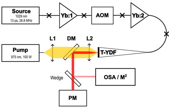
Figure 1.
The experimental setup. Yb:1 and Yb:2 are low-power single-mode core-pumped amplifiers; AOM: acousto-optic modulator; L1 and L2: aspheric lenses, f = 11 mm; DM: dichroic mirror, HR@1030 nm, HT@976 nm; PM: power meter; OSA: optical spectrum analyzer; M2: M2 measurement setup.
3. Optimization of the Tapered Amplifier and Measurement Results
3.1. Tapered Fiber Design
The main purpose of this work was to identify the factors determining the threshold of nonlinear effects in T-YDF amplifiers operating in the spectral range near 1030 nm. Within the framework of the present work, we investigated amplifiers of picosecond pulses; as a rule, this is the pulse duration demanded in most tasks related to the processing of materials. The most obvious factors on which the threshold of nonlinear effects depends are the mode field diameter (MFD) at the output of the tapered fiber, the rate of pump absorption from the cladding, the gain (and accordingly the distribution of signal power along the length of the T-YDF), and the profile of the tapered fiber (the dependence of the core and cladding diameter on the length of the fiber).
It should be noted that earlier [17] a thorough optimization of the tapered fiber design had already been carried out. Thus, the previously obtained absorption from the cladding at the level of 24 dB/m and a wavelength of 976 nm can be increased only by using the design of fiber with a pedestal [12,29], which in turn actually excludes the possibility of creating a polarization-maintaining fiber. In addition, in the case of increasing absorption from the cladding, the thermal load per unit length of the fiber increases significantly. This leads to a sharp decrease in the maximum average output power that can be extracted from the amplifier based on such a fiber [29] and, as a consequence, significantly limits the scope of application of such amplifiers. Thus, the ytterbium concentration and the geometric dimensions of the core and cladding of the tapered fiber used in [17,26] appear to be close to optimal. In the present work, we used a similar design of tapered fiber. Our tapered fibers have an input thin end with a core diameter of 8–9 microns that operates strictly in single-mode regime. Hence, no high-order modes should be excited while the signal propagates along the fiber (if the change in the tapered fiber diameters is slow enough). Such fibers have been studied for a long time by a few groups and, for those tapered fibers where such conditions were met (strictly single-mode input and adiabatic change in core diameter), the output beam quality was always good [9,10,11,17,19,21]. Moreover, mode content analysis performed with the S2 technique showed that in our tapered fibers, the content of high-order modes at the output of the tapered fiber does not exceed 0.3% [26].
The second significant factor affecting the threshold of nonlinear effects is the maximum diameter of the core and, accordingly, the MFD. In this case, the main limitation on the maximum core diameter is the tapered ratio (the ratio of the maximum and minimum fiber diameters). Using our developed technology of non-stationary drawing of the fiber in the manufacture of a short-tapered fiber (1–2 m long), a tapering ratio of 5 can be obtained [17]. The need for a single-mode input end of a tapered fiber results in a core diameter of 8–9 μm with NA of 0.09, which is caused by the high ytterbium content. As a consequence, in the thick part, it is quite difficult to obtain a core diameter significantly larger than 40–50 µm. In this case, it is worth mentioning an alternative approach [30], where tapered fibers are realized with an initially non-single-mode core at the thin end. Acceptable beam quality in this case is achieved by winding a thin part of the tapered fiber on a coil of small diameter, which allows removal of a significant part of the higher modes from the core. The 1.27 m long fiber with such a design was used to achieve a record-high peak power of 1.3 MW at 1064 nm [18]. However, even in this case, the diameter of the core on the side of the thick end of the tapered fiber does not exceed 58 microns. When using such a fiber design, it is difficult to guarantee a single-mode propagation mode, as the achievement of a single-mode propagation mode in fiber with a core diameter of 35 μm is a nontrivial task in itself. For this reason, within the framework of this work, we used the design of fiber with an exactly single-mode thin end, similar to what we used in [17,26]. It should be mentioned that with this fiber configuration, peak power of 1.2 MW was obtained in 2.5 m long T-YDF at a signal wavelength of 1038.5 nm [19].
The next important factor affecting the threshold of nonlinear effects is the length of the tapered fiber. As we showed in [17], reducing the length of the tapered fiber from 2 m to 1 m leads to a significant increase in the SRS threshold when the amplifier operates at a wavelength of 1030 nm. This is likely due to a decrease in signal re-absorption at 1030 nm and a decrease in the fraction of seed radiation for the first Stokes component resulting from ASE generation. On the other hand, reducing the length of the fiber leads to a significant decrease in the maximum possible average power [26], which is also undesirable. At the same time, it is worth noting that in [17] the various modes of operation (gain, average power output) of the amplifier at wavelength 1030 were not investigated in detail. Thus, a taper of similar design with a length of 2 m demonstrated a high SRS threshold at a wavelength of 1039 nm [19]. This suggests that in shorter tapered fibers, it is possible to shift the operating wavelength further into the short-wavelength region. For this reason, in the experiments, we used tapered fibers with a length equal to 1.7 m. It is not desirable to use a significantly shorter tapered fiber length because of the limitation on the maximum coupled pump power as a result of pump leakage due to the vignetting effect [31,32]. An increase in pumping in this case would increase the thermal load on the active fiber in the region of the tapered transition and might reduce the amplifier lifetime [26].
Thus, to increase the peak power at the output of the amplifier, the only thing left to do is to optimize the gain regime and the diameter profile of the T-YDF (variation in the core and cladding diameters along the T-YDF), which is what the majority of our study focused on.
3.2. Nonlinear Effects Limiting Power Scaling in Picosecond Pulse Amplifiers Based on Tapered Fibers
At amplification of pulses with durations ranging from units to hundreds of picoseconds, the main nonlinear effects are SPM and SRS. At the same time, as a rule, SPM leads to a broadening of the radiation spectrum but does not limit the maximum peak power. SRS leads to the coupling of radiation energy into the Stokes component and, as a consequence, a decrease in lasing efficiency and appearance of additional, unwanted pulses at Stokes wavelengths. In fact, it is SRS that is considered to be the main limiting factor in the amplification of picosecond pulses. It is well known that by varying amplifier parameters (for example, by reducing the signal power at the input), it is possible to increase the threshold of SRS occurrence [17,18]. In the process of conducting experiments to find the optimal amplification regime, we found that it is not only SRS but also another nonlinear effect, namely, four-wave mixing (FWM), that starts to limit the output power. As an example, Figure 2 shows the measurement results of T-YDF #2. The dependence of the core and cladding diameters of this tapered fiber on its length is shown in Figure 2a. It was found that when amplifying an input signal with a power of 90 mW, a pulse duration of 13 ps and a repetition rate of 4.47 MHz SRS appear first (Figure 2b shows a spectrum of the signal amplified to 17 W with a black line). When the input signal power is reduced, SRS development is largely suppressed; a broad long-wavelength peak adjacent to the signal is amplified spontaneous luminescence (ASE), and SRS is negligible in this measurement. This optimization of the gain regime allows us to increase the output signal power by one-third, to 26 W, until peaks at wavelengths ~1380 nm and a faint short-wavelength peak at ~820 nm appear in the output signal spectrum. It is worth noting that the short-wave peak is significantly weakened on the spectrum due to the presence of a dichroic mirror, designed to reflect radiation in the range of 1030 nm in the circuit; however, in this regime, the fiber begins to glow intensely with red light, indicating a significant level of this radiation (see insert in Figure 2b). The glowing occurs nearly simultaneously with the appearance of a distinguishable short-wave peak on the spectrum. Knowing the reflection coefficient of the mirror, we found that the observation of red glowing corresponds to ~1 W of power in the short-wave FWM component. We set this value as the FWM limit for further power scaling. The appearance of these components in the spectrum is associated with the development of FWM, which at first glance seems quite strange; effective frequency conversion due to this effect requires phase matching between the pump wavelengths (1030 nm), as well as short-wave and long-wave components (820 nm and 1380 nm). Usually, such phase matching can be realized for the fundamental mode by creating special fiber designs with zero dispersion near the pump wavelength [33]. At the same time, it is known that in the case of a fiber that supports the propagation of several modes, this condition is not necessary, and phase matching can occur with one of the higher modes of the fiber [34]. Analysis of the output radiation showed that indeed, in this case, there is generation of one of the cladding modes of the tapered fiber (inset in Figure 2b). Thus, in addition to SRS, another nonlinear effect, which is FWM, is a factor limiting the maximum peak power at the output of the tapered fiber.
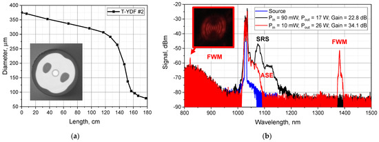
Figure 2.
(a) Diameter profile of T-YDF #2, insert—image of cross section of T-YDF; (b) output signal spectra at different gain regime; insert—image of red glowing at fiber output.
3.3. Dependence of SRS and FWM Thresholds on the Gain Regime
As was shown in the previous paragraph, changing the gain regime of the fiber significantly affects the thresholds of nonlinear effects. In order to investigate this dependence in detail, we conducted experiments to measure the thresholds of SRS and FWM at different repetition rates and input power levels. The thresholds were estimated from the output radiation spectra. Figure 3 shows as an example the characteristic dependence of the power fraction in the unwanted spectral components (in all Stokes wavelengths in the case of SRS and in the Stokes long wavelengths in the case of FWM) on the gain at the same pulse repetition rate of 4.47 MHz, but at different average input signal powers (ranging from 90 to 5 mW). In the present study, we defined the threshold power as the power of the output signal at which the power fraction in the undesired spectral components is at the level of 0.04% of the output power. The figure of 0.04% was chosen after analyzing Figure 3, due to the fact that this power level could be captured for the Stokes components of both nonlinear effects in most measurements. It is interesting to note that FWM develops much faster with increasing pump power than SRS (see Figure 3).
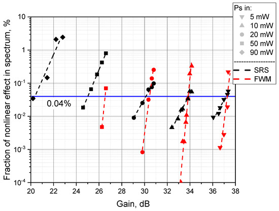
Figure 3.
Power fraction in nonlinear effect at different gain in T-YDF #2.
The pulse repetition rate is another factor that determines the gain regime of the fiber. For example, by changing the pulse repetition rate, it is possible to compare two regimes with the same gain but with different input and output signal powers. In addition, we can keep the peak power of the signal at the input of the T-YDF while changing its average power. In this way, we can check, for example, the relationship between the magnitude of the thresholds of the investigated nonlinear effects and the maximum average power.
In general, we can expect that the main factor that determines the threshold of the nonlinear effects will be the gain. Indeed, since we use the same tapered fiber in the present experiment for a fixed gain but different output power levels, the signal power distribution along the length of the tapered fiber normalized to the signal output power will be almost identical (see Figure 4a). As a consequence, the thresholds of nonlinear effects in this case should be approximately the same.
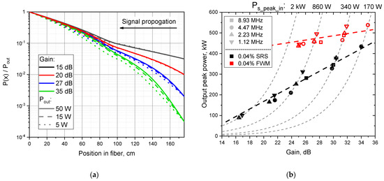
Figure 4.
(a) Normalized power distribution in T-YDF at different gain and output power; (b) dependence of nonlinear effects thresholds on gain at different repetition rates in T-YDF #1 (176 cm).
Figure 4b shows the obtained thresholds of nonlinear effects (SRS and FWM) measured in T-YDF #1 (see T-YDF parameters in Table 2), where for each of the possible repetition frequencies the measurements were performed with different levels of input signal power. It can be seen that the points corresponding to the different repetition frequencies lie on the same curve with reasonably good accuracy. This means that the gain is the main factor determining the thresholds of nonlinear effects, and the influence of the input or output power level itself (at the same gain) is much weaker. In particular, to illustrate the last statement, we have drawn dashed lines, which correspond to the case of signal amplification with fixed peak power at the input, and thus the points lying on the same dashed curve differ only in the average power at the input (as a consequence of changing the pulse repetition rate). It can be seen that in the vast majority of cases, the nonlinear effects threshold is higher at lower frequencies and hence lower average power. However, this dependence is an order of magnitude weaker than the dependence on the gain.

Table 2.
Characteristics of the studied T-YDFs.
It is important to note that FWM is the limiting factor for T-YDF #1 from Figure 4b at large gain. Despite the fact that the SRS threshold, defined as 0.04% in the Stokes component, is reached at lower peak powers, FWM develops much faster than SRS (see Figure 3). Studying the reasons for this behavior is beyond the scope of this article, as FWM occurs with one of high-order modes, and its dispersion properties are difficult to analyze. In this work we limit ourselves by indicating such behavior only.
Based on the above observations, it is logical to conclude that in order to increase the nonlinear effect thresholds, it is necessary to maximize the gain. Unfortunately, such an approach has its own limitations. As the gain increases, the pump-to-signal conversion efficiency decreases (on average, from 60% to 50%) while simultaneously increasing ASE. At a gain greater than 32 dB, the power fraction of ASE in the output emission spectrum can reach several percent, and the power propagating back towards the signal source can reach up to 100–200 mW (at a pump power of ~80 W). Moreover, the high gain corresponds to a high level of inversion of ytterbium ions in the tapered fiber. As a consequence, the rate of pump absorption decreases (the tapered fiber becomes bleached) and more pump reaches the thin end of the fiber, increasing the thermal load on the tapered transition, which must be taken into account when working with high average power. The leakage was observed at the part of the tapered fiber where the outer diameter is reduced below ~150–300 µm (depending on the input pump NA). In accordance with [26], we calculated that it is necessary to keep pump power on the level below 250 W for 15 dB gain and below 230 W for 35 dB gain to guarantee no thermal issue at the leakage point during 105 h of operation.
3.4. Profile of Tapered Fiber Diameter
The next important factor affecting the thresholds of nonlinear effects is the T-YDF diameter profile (the dependence of the core and cladding diameter on the coordinate along the fiber axis). First of all, it is worth paying attention to the total length of the T-YDF. Fiber itself is a nonlinear medium, which means that if we pursue the goal of increasing the nonlinear effects threshold, this parameter must also be optimized. Moreover, the peculiarity of tapered fibers is the fact that the threshold of nonlinear effects with length can both increase and decrease [17]. In addition, the length determines the amount of pumping that the fiber can absorb, as well as the effects of signal re-absorption. It should be noted that we did not consider very short lengths of tapered fiber in this case, as even for a length of 1.7 m in some regimes (with high gain and high output signal power), a significant fraction of the pump begins to pass through the T-YDF.
Our previous work [17] has already investigated the effect of T-YDF length on the SRS threshold value. However, these studies were conducted at relatively low gain, leading to extremely low SRS thresholds (it should be noted that when the length was increased to 2 m, the significant ASE in the 1064 nm region prevented signal amplification at 1030 nm and the correct determination of the SRS threshold). As was shown in the previous paragraph, the maximum threshold of nonlinear effects is reached at high gain. As a consequence, the dependence of the amplifier parameters on the length of the tapered fiber should be checked again.
Figure 5 shows the results of the power comparison of T-YDF #1, the length of which was 207 cm at first, and then, by cutting the thick part, we reduced it to 176 cm. Reducing the length of T-YDF leads to an increase in efficiency of almost one and a half times, from 55% to 73% (Figure 5). The SRS threshold in this case practically did not change (the increase did not exceed 10%) in the whole range of investigated pulse repetition frequencies (1.03–8.93 MHz) and gain coefficients (15–35 dB). At the same time, a slight increase in the FWM threshold (~50–100 kW) was observed. Similar to our previous work [17], the ASE decreased with length reduction; however, in this regime of operation (with high gain) in a 207 cm T-YDF, the ASE fraction did not exceed a couple of percent at the highest gains.
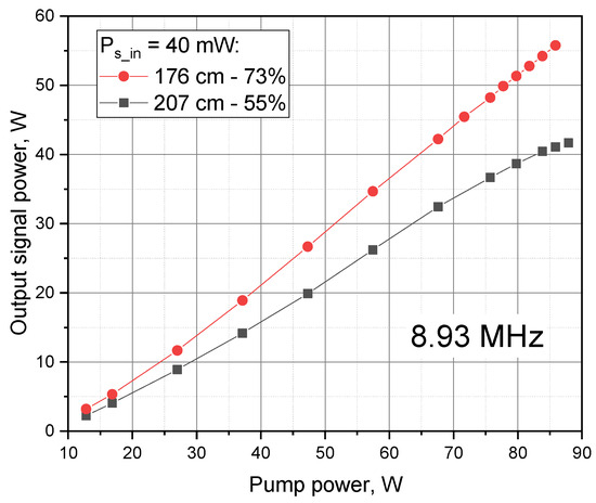
Figure 5.
Pump-to-signal conversion efficiency at different lengths of T-YFD #1.
Next, the influence of the length of the thin part of the T-YDF was tested. In the publication [17], it exceeded 30 cm. In the present work, we compared the thresholds in two T-YDFs having the same length and MFD but different length ratios of the thin and thick parts. In sample #3, the thin part was extremely short, while in sample #1, the thin part had a length of ~59 cm (Figure 6b). In Figure 6a, it is shown that T-YDF #3 with a short narrow part has a ~1.5 times greater SRS threshold than T-YDF #1 in a high gain operation regime. The FWM threshold is also greater in T-YDF #3 (red and black lines). Such behavior is expected as the average value of the diameter along the length of sample #3 is greater than that of sample #1, which is the main condition for increasing the threshold of nonlinear effects.
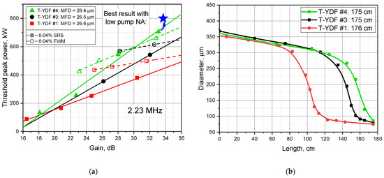
Figure 6.
(a) Dependence of nonlinear effects thresholds on different T-YDF configurations; highest peak power achieved by reducing NA is marked with the blue star; (b) T-YDFs diameter profiles.
From Figure 6, it can be seen that further shortening of the thin part (the diameter profile was changed so that the single-mode regime of the core comes directly after the tapered transition) and increasing the MFD allowed the threshold of SRS to be increased by about 100–150 kW. Larger MFD in T-YDF #4 was achieved due to the perfectly flat refractive index profile of the core [27]. In other tapered fibers, MFD was smaller due to a small rise in the refractive index in the center of the core and corresponding mode shrinking. It is worth noting that, if the refractive index is higher at the edges of the core, it increases the MFD further, but may also lead to deformation of the mode to a donut shape.
Table 2 shows the characteristics of the studied T-YDFs. MFD was measured via the near field technique (by observing the mode’s image with an IR camera) on the level 1/e2 at the output end of the T-YDF. The length of the thin part was defined as the distance from the thin end of the T-YDF to the point where its outer diameter increased to 100 μm. The two pump conversion efficiency values correspond to amplification at high and low gain regimes, respectively. It should be noted that the given threshold values are averaging the results of measurements at several repetition rates in the high gain regime (~31–33 dB). The table clearly demonstrates the growth of thresholds of nonlinear effects with increasing mode field diameter.
3.5. Influence of Numerical Aperture
In the process of the study, it became clear that one more additional factor could affect the thresholds of nonlinear effects. The use of pump radiation with 0.15 NA instead of 0.22 NA allowed us to slightly increase the FWM threshold (the SRS threshold did not change significantly; in Figure 6a, the blue dot marks the best achieved result at 2.23 MHz). Reducing the pump aperture causes more pump power to pass into the thin part, which leads to a slight change in the signal gain profile as well as a change in the heating profile of the fiber. Since the SRS threshold did not change significantly, we believe that in this case the phase matching conditions have changed, which led to a change in the FWM threshold.
3.6. Record Peak Power Directly from T-YDF Amplifier
Having established all factors influencing the value of nonlinear effects thresholds, we chose the regime of tapered fiber operation, which provides the achievement of maximum peak power values for our T-YDFs. For this purpose, we used a 173 cm long T-YDF with a short thin part and the largest MFD value. The coupled pump numerical aperture was 0.15, and the gain lay in the range of 32–36 dB.
First, we tested amplifier behavior at high average power. In T-YDF #5 with a 29.1 µm MFD, a 50 mW input signal with a pulse repetition rate of 4.47 MHz was amplified to 39 W, corresponding to 670 kW peak power. In the output signal spectrum, the fractions of ASE, SRS, and FWM were approximately 0.6%, 0.5%, and 0.1%, respectively.
By reducing the pulse repetition rate to 2.06 MHz, we amplified a 9.2 mW signal to 21 W average and 0.8 MW peak power. In this case, the ASE and SRS did not exceed 1% and 0.5%, respectively. The limiting factor was FWM; ~1 W of power was propagating toward the multimode pump side, but in the output spectrum the FWM fraction was less than 0.1%.
We then lowered the frequency to 1.03 MHz, and the signal was amplified from 5 mW to 13.8 W of average power, corresponding to 1 MW of peak power. At the same time, the ASE fraction was ~2%, SRS was ~0.2%, and the FWM fraction remained negligible in the output signal spectrum (Figure 7). In all the above measurements, the beam quality was close to being diffraction limited (M2 < 1.2), which is typical for tapered fibers having a strictly single-mode thin end [9,10,11,17,19,21]. To the best of our knowledge, the peak powers obtained are the record for the 1030 nm wavelength, and thus a MW level comparable to the results for 1040 and 1064 nm was achieved.
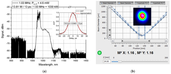
Figure 7.
(a) Output signal spectrum at 1 MW peak power; inset—autocorrelation function (ACF) at T-YDF input; (b) output beam caustics at M2 parameter measurement; inset—image of the output beam.
4. Discussion and Conclusions
As can be seen above, one of the most important factors determining the threshold of nonlinear effects is the gain in the signal. In the examined tapered fibers operated near 1030 nm, increasing the gain from ~16 dB to ~33 dB allowed the SRS threshold to be increased by 4–7 times. In this case, it is quite interesting that the ratio of the lengths of the thin part and the thick part of the tapered fiber apparently affects the rate of growth of the SRS threshold; in the case of a fiber with the shortest thin part, the threshold growth was maximum (by more than seven times).
An increase in gain is expected to lead to the growth in amplified spontaneous emission and pump bleaching of the fiber, which in turn leads to an increase in the unabsorbed pump in the tapered fiber. A rather unexpected result of the present study is that, in addition to SRS, FWM was found to be another nonlinear effect limiting the peak power in lasers with pulse durations of the order of tens of ps. This effect apparently develops due to the phase matching between the radiation amplified in the fundamental mode with a central wavelength of 1030 nm and high-order modes in the visible and near-IR ranges. Excitation of high-order modes is quite possible in the T-YDF since it is double-cladded and its thick part is multimode, despite the signal propagation being solely in the fundamental mode. This means that FWM is predominantly generated in the thick part of the T-YDF, in contrast to SRS, which depends on the length of the thin part of the T-YDF (Figure 3a). This assumption is confirmed by the increase in the FWM threshold when the length of the thick part is reduced (Figure 3a).
Interestingly enough, the FWM was found to be quite sensitive both to the profile of the diameter of the tapered fiber and even to its pumping regime (the FWM threshold varied with the pump numerical aperture). Moreover, in some cases, we observed the generation of several wavelengths in the IR regions of the spectrum (Figure 8), which we attribute to the appearance of phase matching with different high-order modes. In addition, the comparison of different series of tapered fibers showed that the wavelength of FWM peaks is not the same for different T-YDFs. All this suggests that a large number of factors affect the fulfillment of the condition of phase matching in the generation of radiation in the visible and near-infrared ranges. In general, almost all factors (such as the profile of the refractive index, the profile of the fiber diameter along the length, and even the characteristics of the pump source) used affect which higher-order modes will develop interaction and, accordingly, which wavelength of radiation will be generated. As a consequence, the dependence of the FWM threshold on the parameters of the tapered fiber is ambiguous and not necessarily reproducible in another series of T-YDF. Therefore, within the framework of this work, we stopped at the statement that this effect can also limit the maximum peak power of the signal and requires optimization of both of the design features of the tapered fiber (diameter profile along the length and refractive index profile) in order to increase the FWM threshold.
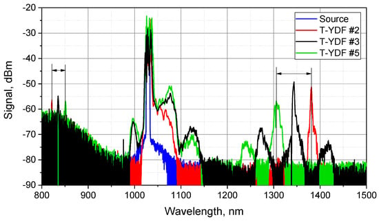
Figure 8.
FWM generation at various wavelengths in different T-YDFs.
Within the scope of the present work, the factors limiting the scaling of peak power in T-YDF in the spectral range of 1030 nm were investigated. It was shown that the signal gain largely determines the maximum achievable peak power; increasing the gain from 17–20 dB to 32–36 dB allows the achievable peak power to be increased by a factor of 3–7. It has been demonstrated that when amplifying picosecond pulses in the T-YDF, in addition to SRS, the FWM also limits the maximum peak power. As a rule, FWM starts to limit the peak power at gains greater than 30–35 dB. By optimizing the shape of the T-YDF diameter profile (reducing the length of the thin part with a corresponding increase in the length of the thick part), the SRS threshold was shown to increase by one and a half times. It was also verified that the increase in the area of the mode at the exit of the tapered fiber (by optimizing the refractive index profile) leads to a proportional increase in the SRS threshold. It was found that the numerical aperture of the pump radiation, which is coupled into the T-YDF from the thick end, can also change the threshold of nonlinear effects.
Figure 9a shows the peak and corresponding average powers achieved. In the cases of points at 1.03 and 2.06 MHz, the limiting factor was FWM. One can see some decrease in the achieved peak power with increasing average power. Thus, with the best amplification regimes, a record peak power of 1 MW at 1029 nm wavelength was achieved directly at the output of the T-YDF with an average power of 13.8 W. Furthermore, a regime with a peak power of 0.8 MW and an average power of 21.5 W was demonstrated. Additionally, a peak power of 670 kW was obtained at an average power of 39 W. All of the above results are records for monolithic fiber amplifiers operated near 1030 nm (Figure 9b).
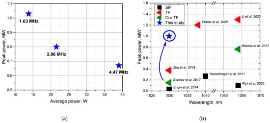
Figure 9.
(a) The powers achieved in the present work; (b) peak powers achieved in setups with fiber signal input [14,15,16,17,18,19,20].
Author Contributions
Conceptualization, M.E.L. and M.M.B.; methodology, M.E.L., K.K.B., A.E.L., V.V.V., S.S.A. and D.S.L.; software, K.K.B.; validation, E.K.M. and K.K.B.; formal analysis, M.E.L.; investigation, E.K.M., K.K.B., T.S.Z.; resources, M.E.L., A.E.L., V.V.V., D.V.K. and D.S.L.; data curation, E.K.M.; writing—original draft preparation, E.K.M.; writing—review and editing, M.E.L. and K.K.B.; visualization, E.K.M.; supervision, M.E.L.; project administration, M.E.L.; funding acquisition, M.E.L. All authors have read and agreed to the published version of the manuscript.
Funding
This work was supported by the Center of Excellence “Center of Photonics” funded by the Ministry of Science and Higher Education of the Russian Federation under Contract 075-15-2022-315.
Institutional Review Board Statement
Not applicable.
Informed Consent Statement
Not applicable.
Data Availability Statement
No data was created.
Acknowledgments
Authors thank the staff of the Large-scale research facility “Fibers” (UNU Fibers) of GPI RAS for the fabrication and characterization of the used fibers.
Conflicts of Interest
The authors declare no conflict of interest.
References
- Teodoro, F.; Hemmat, M.; Morais, J.; Cheung, E. High peak power operation of a 100 μm-core Yb-doped rod-type photonic crystal fiber amplifier. In Proceedings of the SPIE 7580, Fiber Lasers VII: Technology, Systems, and Applications, San Francisco, CA, USA, 25–28 February 2010. [Google Scholar]
- Brooks, C.; Teodoro, F. Multimegawatt peak-power, single-transverse-mode operation of a 100 μm core diameter, Yb-doped rodlike photonic crystal fiber amplifier. Appl. Phys. Lett. 2006, 89, 111119. [Google Scholar] [CrossRef]
- Wang, Z.; Li, Q.; Wang, Z.; Zou, F.; Bai, Y.; Feng, S.; Zhou, J. 255 W picosecond MOPA laser based on self-made Yb-doped very-large-mode-area photonic crystal fiber. Chin. Opt. Lett. 2016, 14, 081401–81404. [Google Scholar] [CrossRef]
- Zou, F.; Wang, Z.; Wang, Z.; Bai, Y.; Li, Q.; Zhou, J. 1-MW peak power, 574-kHz repetition rate picosecond pulses at 515 nm from a frequency-doubled fiber amplifier. In Proceedings of the SPIE 10016, High-Power Lasers and Applications VIII, Beijing, China, 12–14 October 2016. [Google Scholar]
- Ma, X.Q.; Zhu, C.; Hu, I.N.; Kaplan, A.; Galvanauskas, A. Single-mode chirally-coupled-core fibers with larger than 50 μm diameter cores. Opt. Express 2014, 22, 9206. [Google Scholar] [CrossRef]
- Dong, L.; McKay, H.A.; Fu, L.; Ohta, M.; Marcinkevicius, A.; Suzuki, S.; Fermann, M.E. Ytterbium-doped all glass leakage channel fibers with highly fluorine-doped silica pump cladding. Opt. Express 2009, 17, 8962. [Google Scholar] [CrossRef]
- Dauliat, R.; Benoot, A.; Darwich, D.; Jamier, R.; Kobelke, J.; Grimm, S.; Schuster, K.; Roy, P. Demonstration of a homogeneous Yb-doped core fully aperiodic large-pitch fiber laser. Appl. Opt. 2016, 55, 6229. [Google Scholar] [CrossRef]
- Gu, G.C.; Kong, F.T.; Hawkins, T.W.; Jones, M.; Dong, L. Extending mode areas of single-mode all-solid photonic bandgap fibers. Opt. Express 2015, 23, 9147. [Google Scholar] [CrossRef]
- Filippov, V.; Chamorovskii, Y.; Kerttula, J.; Golant, K.; Pessa, M.; Okhotnikov, O.G. Double clad tapered fiber for high power applications. Opt. Express 2008, 16, 1929–1944. [Google Scholar] [CrossRef]
- Kerttula, J.; Filippov, V.; Ustimchik, V.; Chamorovskiy, Y.; Okhotnikov, O.G. Mode evolution in long tapered fibers with high tapering ratio. Opt. Express 2012, 20, 25461–25470. [Google Scholar] [CrossRef]
- Koptev, M.Y.; Anashkina, E.A.; Bobkov, K.K.; Likhachev, M.E.; Levchenko, A.E.; Aleshkina, S.S.; Semjonov, S.L.; Denisov, A.N.; Bubnov, M.M.; Lipatov, D.S.; et al. Fibre amplifier based on an ytterbium-doped active tapered fibre for the generation of megawatt peak power ultrashort optical pulses. Quantum Electron. 2015, 45, 443. [Google Scholar] [CrossRef]
- Sidharthan, R.; Lin, D.; Lim, K.J.; Li, H.; Lim, S.H.; Chang, C.J.; Seng, Y.M.; Chua, S.L.; Jung, Y.; Richardson, D.J.; et al. Ultra-low NA step-index large mode area Yb-doped fiber with a germanium doped cladding for high power pulse amplification. Opt. Lett. 2020, 45, 3828–3831. [Google Scholar] [CrossRef] [PubMed]
- Zhao, Z.; Dunham, B.M.; Wise, F.W. Generation of 150 W average and 1 MW peak power picosecond pulses from a rod-type fiber master oscillator power amplifier. J. Opt. Soc. Am. 2014, B 31, 33–37. [Google Scholar] [CrossRef]
- Roy, V.; Desbiens, L.; Boivin, M.; Grenier, P.; Deshaies, S.; Martineau, Q.; Deladurantaye, M.; Proulx, A.; Taillon, Y. 35/250 ytterbium-doped LMA polarization-maintaining fiber for high average and high peak power amplifiers. In Proceedings of the SPIE 12400, Fiber Lasers XX: Technology and Systems, San Francisco, CA, USA, 28 January–3 February 2023. [Google Scholar]
- Kanzelmeyer, S.; Sayinc, H.; Theeg, T.; Frede, M.; Neumann, J.; Kracht, D. All-fiber based amplification of 40 ps pulses from a gain-switched laser diode. Opt. Express 2011, 19, 1854–1859. [Google Scholar] [CrossRef]
- Engin, D.; Burton, J.; Darab, I.; Kimpel, F.; Mathason, B.; Gupta, S. 1030nm Yb-fiber-MOPA-based, multi-aperture high power, high energy uplink laser beacon for deep space communication. In Proceedings of the SPIE 8971, Free-Space Laser Communication and Atmospheric Propagation XXVI, San Francisco, CA, USA, 1–6 February 2014. [Google Scholar]
- Bobkov, K.; Andrianov, A.; Koptev, M.; Muravyev, S.; Levchenko, A.; Velmiskin, V.; Aleshkina, S.; Semjonov, S.; Lipatov, D.; Guryanov, A.; et al. Sub-MW peak power diffraction-limited chirped-pulse monolithic Yb-doped tapered fiber amplifier. Opt. Express 2017, 25, 26958–26972. [Google Scholar] [CrossRef]
- Li, W.; Ma, P.; Lai, W.; Song, J.; Wang, T.; Ren, B.; Liu, W.; Zhou, P.; Si, L. Tapered active fiber simultaneously enabled 141 W high average and 1.3 MW high peak power via all-fiber and polarization-maintained picosecond amplifier. Opt. Laser Technol. 2022, 152, 108166. [Google Scholar] [CrossRef]
- Petrov, A.; Odnoblyudov, M.; Gumenyuk, R.; Minyonok, L.; Chumachenko, A.; Filippov, V. Picosecond Yb-doped tapered fiber laser system with 1.26 MW peak power and 200 W average output power. Sci. Rep. 2020, 10, 17781. [Google Scholar] [CrossRef]
- Zhu, Y.; Leich, M.; Lorenz, M.; Eschrich, T.; Aichele, C.; Kobelke, J.; Bartelt, H.; Jäger, M. Yb-doped large mode area fiber for beam quality improvement using local adiabatic tapers with reduced dopant diffusion. Opt. Express 2018, 26, 17034–17043. [Google Scholar] [CrossRef]
- Ustimchik, V.; Chamorovskii, Y.; Filippov, V. High average power (500 W/50 ps) and high peak power (3.2 MW/50 ps) picosecond pulsed MOPA system with tapered double-clad ytterbium fiber. In Proceedings of the SPIE 11981, Fiber Lasers XIX: Technology and Systems, San Francisco, CA, USA, 22 January–28 February 2022. [Google Scholar]
- Galvanauskas, A.; Cheng, M.-Y.; Hou, K.-C.; Liao, K.-H. High Peak Power Pulse Amplification in Large-Core Yb-Doped Fiber Amplifiers. IEEE J. Sel. Top. Quantum Electron. 2007, 13, 559–566. [Google Scholar] [CrossRef]
- Leich, M.; Kalide, A.; Eschrich, T.; Lorenz, M.; Lorenz, A.; Wondraczek, K.; Schönfeld, D.; Langner, A.; Schötz, G.; Jäger, M. 2 MW peak power generation in fluorine co-doped Yb fiber prepared by powder-sinter technology. Opt. Lett. 2020, 45, 4404–4407. [Google Scholar] [CrossRef]
- Bogatyrev, V.A.; Bubnov, M.M.; Dianov, E.M.; Kurkov, A.S.; Mamyshev, P.V.; Prokhorov, A.M.; Rumyantsev, S.D.; Semenov, V.A.; Semenov, S.L.; Sysoliatin, A.A.; et al. A single-mode fiber with chromatic dispersion varying along the length. J. Light. Technol. 1991, 9, 561–566. [Google Scholar] [CrossRef]
- Bogatyrjov, V.A.; Sysoliatin, A.A. Efficient method to produce fibers with outer diameter varying along the length. In Proceedings of the SPIE 4204, Fiber Optic Sensor Technology II, Boston, MA, USA, 5–8 November 2000. [Google Scholar]
- Bobkov, K.; Levchenko, A.; Kashaykina, T.; Aleshkina, S.; Bubnov, M.; Lipatov, D.; Laptev, A.; Guryanov, A.; Leventoux, Y.; Granger, G.; et al. Scaling of average power in sub-MW peak power Yb-doped tapered fiber picosecond pulse amplifiers. Opt. Express 2021, 29, 1722–1735. [Google Scholar] [CrossRef]
- Lipatov, D.S.; Guryanov, A.N.; Yashkov, M.V.; Bubnov, M.; Likhachev, M.E. Fabrication of Yb2O3–Al2O3–P2O5–SiO2 Optical Fibers with a Perfect Step-Index Profile by the MCVD Process. Inorg. Mater. 2018, 54, 276–282. [Google Scholar] [CrossRef]
- Kerttula, J.; Filippov, V.; Chamorovskii, Y.; Ustimchik, V.; Golant, K.; Okhotnikov, O. Principles and performance of tapered fiber lasers: From uniform to flared geometry. Appl. Opt. 2012, 51, 7025–7038. [Google Scholar] [CrossRef] [PubMed]
- Bobkov, K.K.; Lipatov, D.S.; Salgansky, M.Y.; Guryanov, A.N.; Bubnov, M.M.; Likhachev, M.E. All-Fiber Chirped-Pulse Amplifier Emitting 670 fs Pulses With 92 MW Peak Power. IEEE Photonics Technol. Lett. 2022, 34, 977–980. [Google Scholar] [CrossRef]
- Cao, X.; Li, Q.; Li, F.; Zhao, H.; Zhao, W.; Wang, Y.; Li, D.; Yang, Y.; Wen, W.; Si, J. Femtosecond Yb-doped tapered fiber pulse amplifiers with peak power of over hundred megawatts. Opt. Express 2023, 31, 5507–5518. [Google Scholar] [CrossRef]
- Veinberg, V.B.; Sattarov, D.K. Waveguide Optics; Chapter 5; Mashinostroenie: Leningrad, Soviet Union, 1977. [Google Scholar]
- Filippov, V.; Kerttula, J.; Chamorovskii, Y.; Golant, K.; Okhotnikov, O.G. Highly efficient 750 W tapered double-clad ytterbium fiber laser. Opt. Express 2010, 18, 12499–12512. [Google Scholar] [CrossRef]
- Nodop, D.; Jauregui, C.; Schimpf, D.; Limpert, J.; Tünnermann, A. Efficient high-power generation of visible and mid-infrared light by degenerate four-wave-mixing in a large-mode-area photonic-crystal fiber. Opt. Lett. 2009, 34, 3499–3501. [Google Scholar] [CrossRef]
- Yatsenko, Y.P.; Pryamikov, A.D.; Mashinsky, V.M.; Likhachev, M.E.; Mavritsky, A.O.; Dianov, E.M.; Guryanov, A.N.; Khopin, V.F.; Salgansky, M.Y. Four-wave mixing with large Stokes shifts in heavily Ge-doped silica fibers. Opt. Lett. 2005, 30, 1932–1934. [Google Scholar] [CrossRef]
Disclaimer/Publisher’s Note: The statements, opinions and data contained in all publications are solely those of the individual author(s) and contributor(s) and not of MDPI and/or the editor(s). MDPI and/or the editor(s) disclaim responsibility for any injury to people or property resulting from any ideas, methods, instructions or products referred to in the content. |
© 2023 by the authors. Licensee MDPI, Basel, Switzerland. This article is an open access article distributed under the terms and conditions of the Creative Commons Attribution (CC BY) license (https://creativecommons.org/licenses/by/4.0/).