Abstract
In this paper, as an introduction, the nonlinear model of a distillation column is presented in order to understand the fundamental paper that the column heating actuator has in the distillation process dynamics as well as in the quality and safety of the process. In order to facilitate the implementation control strategies to maintain the heating power regulated in the distillation process, it is necessary to represent adequately the heating power actuator behavior; therefore, three different models (switching, nonlinear and fuzzy Takagi–Sugeno) of a DC-DC Buck-Boost power converter, selected to regulate the electric power regarding the heating power, are presented and compared. Considering that the online measurements of the two main variables of the converter, the inductor current and the capacitor voltage, are not always available, two different fuzzy observers (with and without sliding modes) are developed to allow monitoring the physical variables in the converter. The observers response is compared to determine which has a better performance. The role of the observer in estimating the state variables with the purpose of using them in the sensors fault diagnosis, using the analytical redundancy concept, likewise, from the estimation of these variables other non-measurable can be determined; for example, the caloric power. The stability analysis and observers gains are obtained by linear matrix inequalities (LMIs). The observers are validated by MATLAB simulations to verify the observers convergence and analyze their response under system disturbances.
1. Introduction
Nowadays, industrial processes have become increasingly complex to meet the quality and speed requirements that society demands. These requirements are reflected in a greater number of components and tasks that must have greater reliability, so they must comply with characteristics such as greater tolerance to failures and wear derived from their continuous operation, which implies the need to have control techniques that allow verifying and monitoring the even under fault conditions.
However, in the control of industrial processes, the online estimation of the variables that are not directly measurable is a fundamental problem, requiring measuring secondary variables that provide information to continuously monitor the status of the process.
One of the control elements used to carry out continuous monitoring of a system, which does not require investing in additional sensors, is the state observer. The observer operation is based on a mathematical model of the system and the information is obtained to reconstruct the variables that cannot be directly or easily measured. State observers can be used in several industrial applications.
One of the most widely used industrial processes today is distillation. Distillation is the process used to separate the components that form miscible liquid mixtures since 800 BC. Distillation is highly used in the chemical, petrochemical, food, pharmaceutical, and perfume industries. Currently, the need to produce chemical substances, such as ethanol, with an increasing demand to satisfy the need for disinfecting products, as well as the generation of biofuels that minimize damage to the environment, has incremented the need for optimal performance of the distillation process.
The distillation column is the most widely used equipment to carry out the distillation process. The operation of a distillation column involves working not only with chemicals but also under pressure and temperature conditions that may result in a risk for the user and the system if there is inadequate monitoring of the process. Figure 1 shows a simplified diagram of the distillation column.
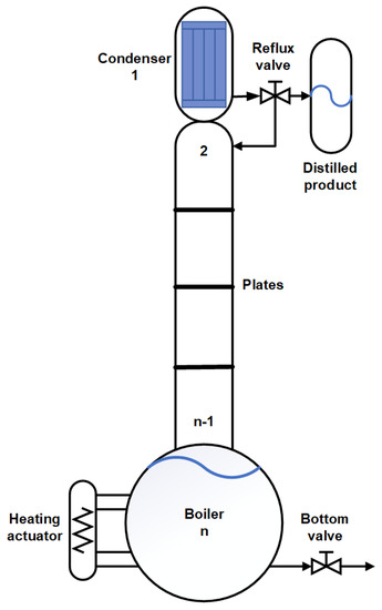
Figure 1.
Distillation column simplified diagram.
Simulation is a key technology in the design, analysis, and operation of distillation columns. The reliability of simulations to represent the real process strongly depends on model quality, which needs to be reliable and predictive [1].
In the literature, modeling and control techniques, such as observers and control systems, have been applied to distillation columns to obtain a better analysis and understanding of the dynamics of the process, improving the quality of the distilled product and enhancing the user safety.
For instance, in [2], the authors model the phase equilibrium in biodiesel production by reactive distillation, The model is validated against experimental results for biodiesel production by reactive distillation. In [3], a surrogate-based optimization of distillation columns is investigated, the authors propose an implicit surrogate to cope with output multiplicities of the model.
In [4], the authors cope with modeling distillation columns with unknown parameters by proposing an intelligent, auto-regressive, exogenous Laguerre (AI-ARX-Laguerre) technique, which achieves average estimation accuracy improvements of 16% and 9% compared with the ARX and ARXLaguerre techniques, respectively.
In [5], a geometric observer (GO) based on the data from the Automatic Continuous Online Monitoring of Polymerization reactions (ACOMP) system for a semi-batch free radical polymerization reactor is presented.
In [6], a distributed high-gain observer design for a binary distillation process and another chemical process is presented and validated.
However, although there exist different works regarding the design and validation of distillation column models and observers, the importance of the related actuators is not always considered.
Actuators in a distillation column are fundamental in the process dynamics since they can modify physical process variables, such as temperature and pressure [7], modifying the purity of the product from reflux [8] or the speed of distillation.
The boiler actuator provides the amount of heat that is necessary to heat and evaporate the mixture to be distilled. This actuator generally controls the heat output by controlling electrical power. The amount of caloric power generated allows for controlling the speed for distillation in the process.
There are different ways to generate heat in a distillation column boiler, some of them use combustion appliances, such as natural gas, propane, and oil furnaces, which are cheap but difficult to control. An alternative is using heating resistors (Figure 2), which generated heat can be controlled by using an electronic power converter that can regulate the electric power that feeds the resistor.
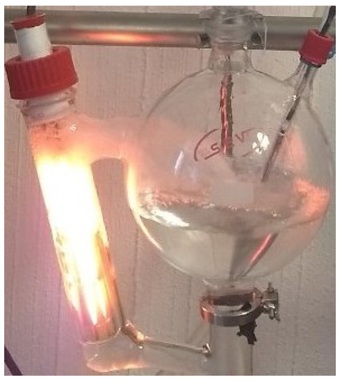
Figure 2.
Distillation column heating actuator.
As in the distillation columns, adequate modelling can facilitate the development of a control task, allowing to monitor the process dynamics by using state observers.
Different power converters models have been reported in the literature. Authors in [9] present a small-signal model for a single-stage PV fed Buck converter that acts as a battery charge-controller in order to improve its MPPT performance. In [10], a multi-physics model of Building-integrated photovoltaics (BIPV) integrated DC/DC converter is developed to quantify the potential of BIPV.
Other authors have reported models of different power converters such as a bidirectional DC/DC Buck [11], switching converters with power semiconductor filters [12] and a three-level T-type grid-connected converter system [13].
Additionally, different observers related to power converters have been reported. In [14], the authors estimate the power electronics modules by using a reduced-order state-space observer. A disturbance estimator to minimize the estimation error is coupled to the observer.
The developed observers can be used combined with other control structures, such as the observer developed in [15], where the authors estimate capacitor voltages from a modular multilevel converter and correct the estimation error by using a sliding mode control.
In [16], a Luenberger observer used as a residual generator is presented. The residuals help to detect open circuit faults in the power transistors of a DC-DC converter applied to a fuel cell. The inductor current is selected as a diagnostic variable to avoid the use of additional sensors to the system.
In [17], the design and simulation of a fault detection system based on a Luenberger observer are presented. This observer is used as a residual generator applied in DC-DC converter with Boost topology. The system detects faults in the voltage and current sensors used in the converter. The proposed system can reconfigure the converter output through the residual analysis.
In this paper, a Takagi–Sugeno fuzzy model that represents a Buck-Boost converter, used to regulate the heating power in a distillation column boiler is presented. The heating power is selected due to its impact in the thermal performance of the distillation process; when the thermal behavior of the columns is unstable can derive in several problems, for instance, a thermal shock to the boiler mixture can cause a violent siphon effect, affecting the measurements, the rate of the distilled product, and even the security of the process.
The developed Takagi–Sugeno fuzzy model is based on four fuzzy rules corresponding to two maximum and minimum operating points selected from the simulation of the case study. The Takagi–Sugeno model is simulated in Matlab and compared to the corresponding reduced nonlinear model of the converter in order to verify its performance.
Additionally, two different fuzzy observers based on the Takagi–Sugeno fuzzy model are presented and compared. The Takagi–Sugeno fuzzy observers difference is the inclusion or absence of a sliding mode term. The observer gains are obtained by linear matrix inequalities (LMIs), which are solved using mathematical software according to the methodology presented by [18].
2. Case Study: Distillation Column Heating Actuator
A distillation column is made up of three main parts: a condenser, a boiler, and the column body consisting of perforated plates. The vapor flow ascends through the plates of the column body enriching the light element (the element with the lowest boiling point of the mixture).
The vapor that reaches the condenser is condensed and, according to the state of the reflux valve, extracted as a distilled product or returned to the column. The returned liquid descends by gravity in the body of the column, enriching the heavy element (the element with the highest boiling point). Each plate in the distillation column corresponds to a degree of purity of the light element, known as the mole fraction.
Fractional distillation is used to separate homogeneous liquid mixtures in which the difference between the boiling points of the components is less than C. Each of the separated components is called a fraction.
In a distillation column, it is essential to continuously monitor all of the process variables to guarantee the quality and quantity of the distilled product, as well as the safety of the process and operators. To achieve this objective, it is necessary to have adequate control techniques.
2.1. Distillation Column Nonlinear Model
The mathematical model of a distillation column consists of a set of differential equations that represent the dynamics of each plate in the column in a stable state, i.e., when the first drop is distilled. Generally, the model of a distillation column is based on the balance of the light component in all of the plates, as shown in (1).
where V is the molar vapor flow, L the molar liquid flow, the retained mass in plate i, the liquid composition in plate i, the vapor composition in plate i, the liquid composition in plate , the vapor composition in plate , the liquid composition in plate , and the vapor composition in plate , with .
The diagram of the condenser is shown in Figure 3, its dynamics are expressed by the Equation (2), and the condenser is denominated as plate 1.
where is the retained mass in the condenser, the liquid composition in the condenser, the vapor composition in the condenser, the liquid composition in plate 2, the vapor composition in plate 2, and D the distilled product.
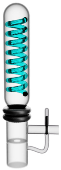
Figure 3.
Distillation column condenser.
Figure 4 shows the scheme of a plate in the body column as well as the variables that are involved in the plate dynamics, expressed in Equation (3).
with i = 2, 3, … n − 1.
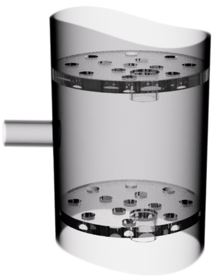
Figure 4.
Plates in the column body.
Figure 5 shows a scheme of the boiler in a distillation column, denominated plate n, its dynamics is presented in (4).
where is the retained mass in the boiler, the liquid composition in the boiler, the vapor composition in the boiler, the liquid composition in plate , and n the total number of plates.
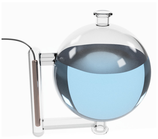
Figure 5.
Distillation column boiler.
Besides, the molar flows are considered in the model, in a batch distillation column these flows are [19]: vapor molar flow (5), liquid molar flow (6), and distilled product (7).
where is the heating power, the reflux, the vapor enthalpy of the light component in the mixture, and the vapor enthalpy of the heavy component in the mixture.
As can be seen, the heating power determines the distillation column dynamics, thus it is essential to have an adequate representation of its behavior.
2.2. Heating Actuator (Boiler) Model
The heating power is determined by the Joule law of heating [20] expressed as:
The power of heating generated by an electrical conductor is proportional to the product of its resistance and the square of the electric current passing through the conductor and the time the current flows through the wire.
The Joule law is defined by (8)
where J is the generated heat in joules, i the electrical current in amperes, R the resistance in ohms and t the time in seconds.
The law of conservation of energy affirms that energy cannot be created or destroyed, it can only be changed from one form to another. Joule’s Law expressed in Electric Power (P) is expressed in (9):
The heating resistance converts electrical energy into heat by circulating current in the conductor; therefore, the thermal power of a boiler can be manipulated and modeled on the electrical power dissipated by the resistance.
Figure 6 shows the actuator scheme, which adjusts the power in the boiler heating resistor by regulating the voltage with a DC-DC converter. This is a simplified model of the buck-boost converter [21], widely used for the analysis of its operation and control [22,23,24,25,26]. DC-DC converters can regulate the output voltage to the desired value from the switching of electronic devices, usually diodes and transistors. Differences with the actual behavior of the converter are compensated by the further inclusion of a state observer.
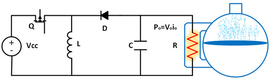
Figure 6.
Scheme of the heating power actuator.
These power electronics converters have applications in renewable energy systems, smart grids, and home and laboratory equipment power systems [27,28]. The basic topologies of DC-DC converters are Buck, Boost, and Buck-Boost [21]. The Buck converter is characterized by the output voltage being lower than the input voltage, the Boost converter is characterized by the output voltage being greater than the input voltage and the Buck-Boost converter is a step-down converter, depending on the cycle (d). For d less than 0.5, the converter reduces the voltage and for d more than 0.5 the voltage is increased.
The operating principle of DC-DC converters is the switching of topological states.
3. Buck-Boost Converter Models
3.1. State-Space Model of the Buck-Boost Converter
The model of the Buck-Boost converter is obtained from commuting the Q switch on and off, which is, from the set of expressions obtained by each topological state. The system is represented as the states matrix form (10) taking as state variables the inductor current () and the capacitor voltage ().
During the on time (), the converter is described by (11):
During the off time (), the converter is described by (12):
The resulting model of the Buck-Boost converter is a commuting model between two linear subsystems, represented in (11) and (12), which commutation depends on the switch state Q. The general representation of the system in matrix form (10) is expressed in (13).
where k is the subsystem for each switch state:
Switching Model Simulation
The parameters of the electrical variables of converter operation, considered as a specific case study, are presented in Table 1.

Table 1.
Buck-Boost converter operation parameters.
Figure 7 and Figure 8 show the simulation of the Buck-Boost converter dynamics, as well as the output ripple, when considering initial conditions in the state variables equal to zero ().
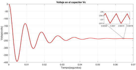
Figure 7.
Capacitor voltage in the Buck-Boost switching model.
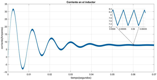
Figure 8.
Inductor current in the Buck-Boost switching model.
3.2. Nonlinear Model
3.3. Takagi–Sugeno Fuzzy Model
The Takagi–Sugeno Fuzzy Model has an important advantage, because it analyzes the operation range of nonlinear systems, using the local sector concept; this means that it takes advantage of the characteristic of the physical systems which are bounded, which allows for modeling the nonlinear systems through a linear subsystems set.
Based on the nonlinear model of the Buck-Boost converter presented in (16) and considering as fuzzy variables the states () that operate between maximum and minimum nominal values (), a Takagi–Sugeno (T-S) fuzzy model that interpolates between four linear submodels based on the following rules is proposed:
| Rule 1: |
| If is and if is |
| Then: |
| Rule 2: |
| If is and if is |
| Then: |
| Rule 3: |
| If is and if is |
| Then: |
| Rule 4: |
| If is and if is |
| Then: |
According to the converter characteristics, the linear submodels are obtained while using the nonlinear sector (). Where:
The membership functions () for the fuzzy sets are determined by Equation (17) for the capacitor voltage :
and Equation (18) for the inductor current :
The normalized weights are given by (19):
The T-S fuzzy model for the DC-DC converter is given in (20) when considering .
3.4. Models Comparison
In this section, the converter nonlinear and the Takagi–Sugeni models are compared to the response of the switching model in simulation.
In the models simulation in 0.1 s, the load is decreased to 78.94.88% () of its nominal value, in 0.2 s it is increased to 113.79% (). In 0.3 s, two simultaneous disturbances are simulated, the load increases to 113.79% () of its nominal value, and the input voltage is increased to 116.66% ( V) of its nominal value.
Figure 9 shows the behavior of the capacitor voltage () as compared to the nonlinear and the Takagi–Sugeno models response.
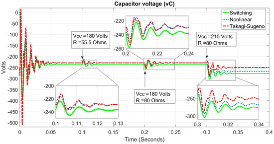
Figure 9.
Comparison of the models capacitor voltage dynamics.
Figure 10 shows the behavior of the inductor current () as compared to the nonlinear and the Takagi–Sugeno models response.
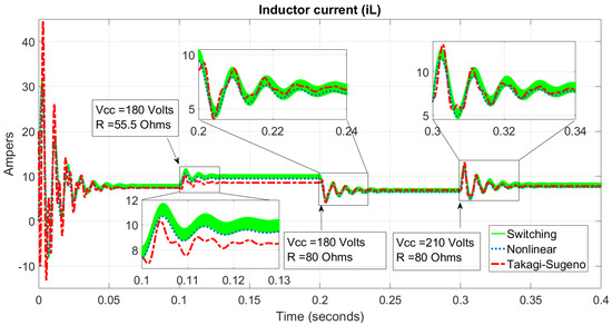
Figure 10.
Comparison of the models inductor current dynamics.
The Takagi–Sugeno model has an adequate response as long as the system dynamics are constrained into the operating points used for its design.
4. Observers
A state observer is a dynamic system that estimates state variables or parameters from available measurements. Observers, also called virtual sensors, are widely used because they allow estimating difficult-to-measure variables of a system from available mathematical algorithms and measurements, and they are also suitable for detecting and locating faults in actuators and sensors.
Observers have a systematic and simple design procedure, facilitating their implementation and execution in real time. The mathematical model is a fundamental part of an observer since it allows describing the dynamics of a real system.
Given a system expressed in the form (10), the observer general equation for reconstructing or estimating states of a system is described in (21):
where represents the estimated state during time and the estimated output is defined in (22):
The system that is presented in (21) and (22) is also denoted as observer Luenberger identity and it is coupled to the original process through the inputs and outputs, as shown in Figure 11. The observer consists of two parts: a predictive stage, based on the model of the observed system, and a corrective stage, formed by the estimation error defined by the difference between the real output and the estimated output , expressed in (23):
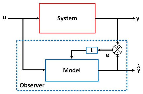
Figure 11.
State observer general scheme.
4.1. Fuzzy Observer
Combining the Takagi–Sugeno fuzzy model of a nonlinear system expressed in (24) with the Luenberger observer (21), the general structure of a fuzzy observer is obtained [29].
Tanaka, in [18], demonstrates the stability of the fuzzy observer as long as there is a P matrix that satisfies the LMI’s expressed in (25):
4.2. Robust Observer under Parameter Variation
The general structure of the observer with sliding modes proposed in [30], is expressed in (26)
where, is the sliding-mode discontinuous vector.
For the convergence analysis, the estimation error is defined in (27).
The error dynamics is defined in (28)
where is defined in (29).
where the Lyapunov function expressed in (30)
is derived (30) omitting the time dependence.
and is defined as (32).
Rewriting (31)
Because corresponds to a Lyapunov inequality, it is defined negative, so the is negative. To achieve the condition of , it is proposed that has the following form.
where M is a constant positive gain. is a defined positive matrix, which must fulfill the Lyapunov equation.
4.3. Fuzzy Observer with Sliding Modes
The fuzzy observer with sliding modes [31] is based on the Luenberger observer [32] for linear systems and the Tanaka fuzzy observer [29].
Using the fuzzy observer (24), it is possible to build local observers with sliding modes for each linear subsystem [30]. Each observer is associated with a fuzzy rule i, given as:
| If: |
| is and, …, and is , |
The complete observer is given by the weighted sum of each subsystem.
is the discontinuous vector of sliding modes for the subsystem i, which has the following form:
where is a positive constant, so the Lyapunov equation is fulfilled, and is defined as the estimated state error.
The stability of the complete observer is demonstrated if each pair , is observable and fulfills the Lyapunov equation.
where,
The structure of the fuzzy observer with sliding modes for Takagi–Sugeno systems defined in [31,33] is expressed in (43).
The fuzzy observer estimation error with sliding modes is determined by
and is the discontinuous vector of sliding modes for the subsystem i, when considering the estimation error as the sliding surface expressed in (45):
The stability of the fuzzy system expressed in (43) is obtained using quadratic Lyapunov functions of the form (46);
Asymptotic stability is guaranteed if there is a defined positive P matrix () such that fulfills the Lyapunov equation expressed in (47).
for each subsystem with .
The resulting linear matrix inequalities (LMI) that guarantee the stability of the fuzzy observer in all subsystems and their combinations are expressed in (48):
Observer gains are defined by the LMI’s system solution defined in (49)
5. Fuzzy Observer for the Heating Resistor Actuator
According to the fuzzy Takagi–Sugeno model for the boiler Buck-Boost converter defined in (20), the expression of the fuzzy observer with sliding modes for Buck-Boost converter is defined in (50).
The observer estimation error is defined by the difference of the nonlinear model states of the converter () and the estimated states of the fuzzy observer () expressed in (52).
The block diagram of the observer applied to the Buck-Boost converter is shown in Figure 12, where the fuzzy variables () are the states of the system (), the gains of the fuzzy observer are defined as and .
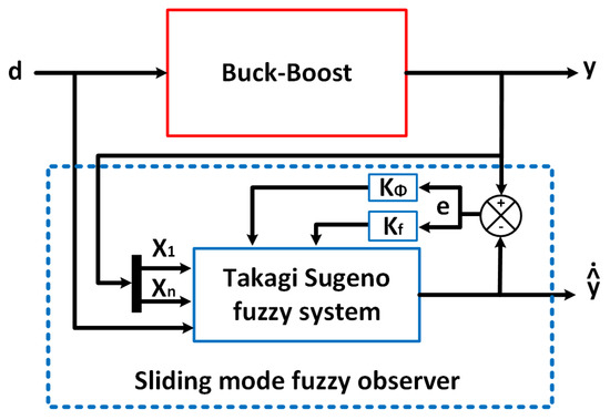
Figure 12.
DC-DC converter fuzzy observer.
According to the characteristics of the converter fuzzy model of the converter (20), where the state matrices are identical, the LMI’s system to guarantee the stability of the fuzzy observer for the Buck-Boost converter is defined in (53).
Given the solution for , the gain for the observer is determined by (54)
6. Discussion, Analysis and Results
The observer simulation is performed for a Buck-Boost converter that regulates the voltage to a 350 W heating resistor for a distillation column boiler.
The observer design parameters are determined for the case study presented in Table 2; and, the behavior of observer is validated by simulation in MATLAB when considering the following disturbances: variation in input voltage to the converter caused mainly by the supply voltage (line voltage) and variations in load are usually due to degradation or manufacturing of the heating resistance.
Table 2.
Parameters of the Buck-Boost converter.
According to the characteristics of the fuzzy system, where , the LMI’s system used to determine the stability of the fuzzy system with eight closed-loop rules with observer is expressed in (55).
The LMI’s that represent the overlaps of the membership functions are expressed in (56)
6.1. Simulation and Comparison of the Heating Actuator Observers
The observer simulation is performed for a Buck-Boost converter with the characteristics presented in Table 2.
Figure 13 shows the simulation in the voltage transient in the capacitor () with different initial conditions of the observer and the nonlinear model ( V, V), where the convergence of the fuzzy observer () is shown at 400 s, and the convergence of the fuzzy observer with sliding modes is shown at 9 ms.
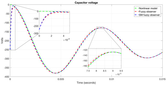
Figure 13.
Voltage transient in with different conditions, 0 V and V.
Figure 14 shows the transient in the inductor current () with different initial conditions between the observer and the nonlinear model ( A and A), where the convergence of the fuzzy observer is shown at 100 s and the convergence of the fuzzy observer with sliding modes is shown at 14 ms.
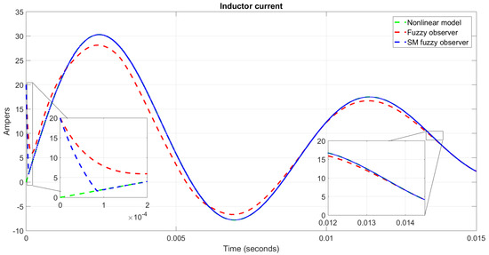
Figure 14.
Current transient in with different conditions, ( A, A).
Figure 15 shows the convergence of the observer in the capacitor voltage with disturbances in the nominal input voltage ( V). In the observer simulation in s, the voltage is decreased to 88.88% ( V) of its nominal value, in s it is increased to 111.11% ( V), in both cases, the observer () converges to the capacitor voltage () of the nonlinear model under these disturbances. The observer has a maximum estimation error of V and a minimum error of 100 V due to the chattering effect of the sliding surface.
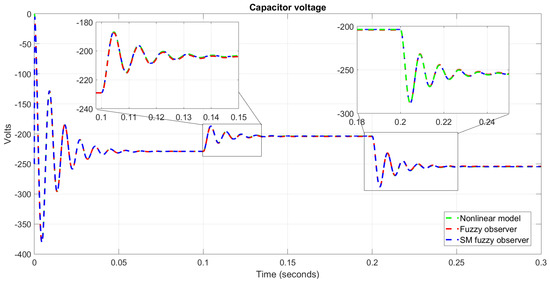
Figure 15.
Observer response for the voltage with disturbances in the supply voltage .
Figure 16 shows the convergence of the observer in the inductor current before disturbances in the nominal input voltage ( V). In s the voltage is decreased to 88.88% ( V) and, in s, it is increased to 111.11% V, in both cases the observer () converges to the current in the inductor () of the nonlinear model before these disturbances. The observer presents a maximum estimation error of 394 mA and a minimum error of 80 A.
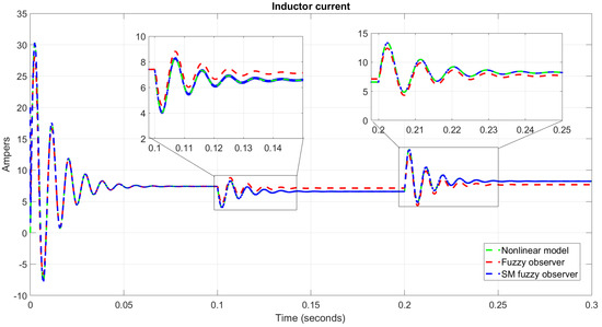
Figure 16.
Observer response for the inductor current with disturbances in supply voltage .
Figure 17 shows the observer convergence in the capacitor voltage under variations in the nominal load (). In s the load is decreased to 78.23% () and in s it is increased to 113.79% (), in both cases, the observer () converges to the capacitor voltage () of the nonlinear model. The observer has a maximum error of 1 V and a minimum of 75 V.
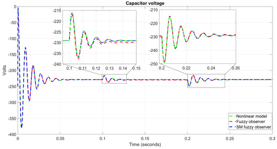
Figure 17.
Observer response for the voltage of with variations in load R.
Figure 18 shows the observer convergence in the inductor current under variations in the nominal magnitude of the load (). In s, the load is decreased to 78.23% () and, in s, it is increased to 113.79% (), in both cases the observer converges on the inductor current. The observer has a maximum error of 13 mA and a minimum error of 100 A.
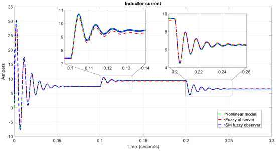
Figure 18.
Observer response on inductor current with variations in load R.
According to the simulation results of the fuzzy observer with sliding modes for the actuator and the experimental validation for the distillation column, it is verified that the fuzzy observer with sliding modes complies with the necessary characteristics of convergence and robustness under disturbances in order to design and implement fault detection and diagnosis systems with analytical redundancy.
6.2. Heating Behavior in the Distillation Column
Regulating the inductor current and the capacitor voltage in the converter implies to regulate the output electrical power, Equation (9), that energies the electrical resistor in the heating actuator of the distillation, hence regulating the heating power, as presented in Equation (5), defines the distillation dynamics.
A distillation process is performed considering an Ethanol–Water mixture in order to validate the power regulation effect in a distillation column. The parameters of the mixture components are specified in Table 3.
Table 3.
Parameters of the Ethanol–Water mixture.
Table 4 presents the initial parameters of the process.
Table 4.
Initial parameters of the distillation process.
The minimum electrical power required to boil the selected mixture is experimentally determined in 180 watts for the used distillation pilot plant.
This distillation pilot plant is formed by the boiler (plate 1), nine plates, and the condenser (plate 11). Seven RTD Pt-100 sensors are located in plates 1, 2, 4, 6, 8, 10, and 11, allowing to monitor the plates temperatures required to estimate the mixture compositions in the column.
In the state-space model of a distillation column described in Equation (58), the inputs to the system are the heating power (), and the reflux valve (), where the heating power is defined by the electrical power used in the boiler heating actuator defined by the output voltage and the heating resistance, determined by Equation (59). The heating power influence in the thermal behavior of the column is denoted in Equation (5).
Two different tests are performed to validate the regulation effect of the heating power in the distillation process. In both processes, the distillation column is heated and maintained in the steady-state, when considering that the reflux valve is always off, i.e., the not distilled product is retired from the column.
Figure 19 shows the temperatures measured in the distillation plates when a non-regulated power supply is used.
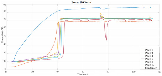
Figure 19.
Thermal behavior of the distillation column using a non-regulated power supply.
Figure 20 shows the temperatures measured in the distillation plates when the presented Buck-Boost converter is used.
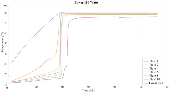
Figure 20.
Thermal behavior of the distillation column using the regulated power supply.
As can be seen in Figure 19, when the electrical power supplied to the heating actuator of the distillation column is not regulated, the thermal performance of the distillation process is unstable, which can derive in several problems, due to a thermal shock to the boiler mixture being able to cause a violent siphon effect, affecting the measurements and the rate of the distillation process. These problems are avoided when using a controlled power, as shown in Figure 20.
7. Conclusions
The heating behavior of the distillation column depends mostly on the boiler and its heating actuator, which must be monitored to guarantee its adequate operation.
In this work, a fuzzy model and two fuzzy observer to estimate the inductor current and capacitor voltage in a DC-DC Buck-Boosy power converter, used to regulate the heating power in a distillation column boiler, are presented.
The observer is based on the Takagi–Sugeno fuzzy model of four rules. The gains are calculated by means of LMIs in order to guarantee the stability for each of the closed loop linear subsystems.
The fuzzy model and fuzzy observers are validated in simulation. Different tests were carried out with ideal and different initial conditions between the nonlinear system and the fuzzy observer, as well as disturbances in the nonlinear system, in order to validate the fuzzy observer convergence.
The Takagi–Sugeno fuzzy observer has an adequate response as long as the disturbances occur in the operating points selected in its designing stage. By adding the sliding-mode term, the fuzzy observer increases its robustness under load and input voltage perturbations, making it suitable to be applied in different control strategies, such as Fault Detection and Isolation (FDI) and Fault Tolerant Control (FTC) systems.
Author Contributions
Conceptualization, J.A.-M. and A.d.C.T.-A.; methodology and formal analysis, M.H.-C.; writing—review and editing, A.d.C.T.-A. and M.H.-C.; supervision, E.E.-J. All authors have read and agreed to the published version of the manuscript.
Funding
This research received funding from Scientific Research Coordination, UMSNH (Conv. 2016–2017) and Conacyt grant number 401203.
Acknowledgments
Authors thank Juan Jesús Silva Romero for the experimentation support.
Conflicts of Interest
The authors declare no conflict of interest.
References
- Asprion, N. Modeling, Simulation, and Optimization 4.0 for a Distillation Column. Chemie Ingenieur Technik 2020, 92, 879–889. [Google Scholar] [CrossRef]
- Albuquerque, A.A.; Ng, F.T.; Danielski, L.; Stragevitch, L. Phase equilibrium modeling in biodiesel production by reactive distillation. Fuel 2020, 271, 117688. [Google Scholar] [CrossRef]
- Keßler, T.; Kunde, C.; McBride, K.; Mertens, N.; Michaels, D.; Sundmacher, K.; Kienle, A. Global optimization of distillation columns using explicit and implicit surrogate models. Chem. Eng. Sci. 2019, 197, 235–245. [Google Scholar] [CrossRef]
- Piltan, F.; TayebiHaghighi, S.; Jowkar, S.; Bod, H.R.; Sahamijoo, A.; Heo, J.S. A Novel Intelligent ARX-Laguerre Distillation Column Estimation Technique. Int. J. Intell. Syst. Appl. 2019, 11, 52–60. [Google Scholar] [CrossRef]
- Salas, S.; Romagnoli, J.A.; Tronci, S.; Baratti, R. A geometric observer design for a semi-batch free-radical polymerization system. Comput. Chem. Eng. 2019, 126, 391–402. [Google Scholar] [CrossRef]
- Yin, X.; Liu, J. Distributed state estimation for a class of nonlinear processes based on high-gain observers. Chem. Eng. Res. Des. 2020, 160, 20–30. [Google Scholar] [CrossRef]
- Paraschiv, N.; Olteanu, M. Feedforward process control of a distillation column based on evolutionary techniques. In Proceedings of the 2015 19th International Conference on System Theory, Control and Computing (ICSTCC), Cheile Gradistei, Romania, 14–16 October 2015; pp. 730–735. [Google Scholar]
- Shafeeq, A.; Daood, S.S.; Muhammad, A.; Ijaz, A. Effect of variable reflux ratio on binary distillation in a laboratory scale distillation column. In Proceedings of the 2010 2nd International Conference on Chemical, Biological and Environmental Engineering, Cairo, Egypt, 2–4 November 2010; pp. 35–38. [Google Scholar]
- Venkatramanan, D.; John, V. Dynamic modeling and analysis of buck converter based solar PV charge controller for improved MPPT performance. IEEE Trans. Ind. Appl. 2019, 55, 6234–6246. [Google Scholar] [CrossRef]
- Spiliotis, K.; Gonçalves, J.E.; Van De Sande, W.; Ravyts, S.; Daenen, M.; Saelens, D.; Baert, K.; Driesen, J. Modeling and validation of a DC/DC power converter for building energy simulations: Application to BIPV systems. Appl. Energy 2019, 240, 646–665. [Google Scholar] [CrossRef]
- Ortigoza, R.S.; Juarez, J.N.A.; Sanchez, J.R.G.; Cruz, M.A.; Guzman, V.M.H.; Taud, H. Modeling and experimental validation of a bidirectional DC/DC buck power electronic converter-DC motor system. IEEE Lat. Am. Trans. 2017, 15, 1043–1051. [Google Scholar] [CrossRef]
- Fan, J.W.T.; Chow, J.P.W.; Chan, W.T.; Zhang, K.; Relekar, A.; Ho, K.W.; Tung, C.P.; Wang, K.W.; Chung, H.S.H. Modeling and experimental assessment of the EMI characteristics of switching converters with power semiconductor filters. IEEE Trans. Power Electron. 2019, 35, 2519–2533. [Google Scholar] [CrossRef]
- Xu, S.; Zhang, J.; Huang, Y.; Jatskevich, J. Dynamic average-value modeling of three-level T-type grid-connected converter system. IEEE J. Emerg. Sel. Top. Power Electron. 2019, 7, 2428–2442. [Google Scholar] [CrossRef]
- Dong, X.; Griffo, A.; Hewitt, D.A.; Wang, J. Reduced-Order Thermal Observer for Power Modules Temperature Estimation. IEEE Trans. Ind. Electron. 2019, 67, 10085–10094. [Google Scholar] [CrossRef]
- Grégoire, L.A.; Wang, W.; Seleme, S.I.; Fadel, M. High reliability observers for modular multilevel converter capacitor voltage evaluation. In Proceedings of the 2016 IEEE 8th International Power Electronics and Motion Control Conference (IPEMC-ECCE Asia), Hefei, China, 22–26 May 2016; pp. 2332–2336. [Google Scholar]
- Zhuo, S.; Gaillard, A.; Xu, L.; Liu, C.; Paire, D.; Gao, F. An Observer-Based Switch Open-Circuit Fault Diagnosis of DC-DC Converter for Fuel Cell Application. IEEE Trans. Ind. Appl. 2020, 56, 3159–3167. [Google Scholar] [CrossRef]
- Li, J.; Zhang, Z.; Li, B. Sensor fault detection and system reconfiguration for DC-DC boost converter. Sensors 2018, 18, 1375. [Google Scholar] [CrossRef] [PubMed]
- Tanaka, K.; Sugeno, M. Stability analysis and design of fuzzy control systems. Fuzzy Sets Syst. 1992, 45, 135–156. [Google Scholar] [CrossRef]
- Skogestad, S. Dynamics and control of distillation columns: A tutorial introduction. Chem. Eng. Res. Des. 1997, 75, 539–562. [Google Scholar] [CrossRef]
- Hyde, J.; Cuspinera, A.; Regué, J. Control Electroneumático y Electrónico; Marcombo: Barcelona, Spain, 1997; Volume 2. [Google Scholar]
- Rashid, M.H. Power Electronics Handbook; Butterworth-Heinemann: Oxford, UK, 2017. [Google Scholar]
- Boora, A.A.; Zare, F.; Ledwich, G.; Ghosh, A. A general approach to control a positive buck-boost converter to achieve robustness against input voltage fluctuations and load changes. In Proceedings of the 2008 IEEE Power Electronics Specialists Conference, Rhodes, Greece, 15–19 June 2008; pp. 2011–2017. [Google Scholar]
- Zhou, X.; He, Q. Modeling and simulation of Buck-Boost converter with voltage feedback control. In Proceedings of the 2015 7th International Conference on Mechanical and Electronics Engineering, Bali, Indonesia, 1–2 July 2015. [Google Scholar]
- Çorapsiz, M.R.; Kahveci, H. Voltage Control Strategy for DC-DC Buck-Boost Converter. In Proceedings of the 4th International Conference on Advanves in Natural & Applied Sciences, Agri, Turkey, 19–22 June 2019; pp. 436–446. [Google Scholar]
- Feshara, H.F.; Ibrahim, A.M.; El-Amary, N.H.; Sharaf, S.M. Performance evaluation of variable structure controller based on sliding mode technique for a grid-connected solar network. IEEE Access 2019, 7, 84349–84359. [Google Scholar] [CrossRef]
- Javed, K.; Vandevelde, L.; De Belie, F. Feed-Forward Control Method for Digital Power Factor Correction in Parallel Connected Buck-Boost Converter (CCM Mode). In Proceedings of the 2020 International Symposium on Power Electronics, Electrical Drives, Automation and Motion (SPEEDAM), Sorrento, Italy, 24–26 June 2020; pp. 827–831. [Google Scholar]
- Arazi, M.; Payman, A.; Camara, M.B.; Dakyo, B. Study of different topologies of DC-DC resonant converters for renewable energy applications. In Proceedings of the 2018 Thirteenth International Conference on Ecological Vehicles and Renewable Energies (EVER), Monte Carlo, Monaco, 10–12 April 2018; pp. 1–6. [Google Scholar]
- Rojas, C.A.; Kouro, S.; Perez, M.A.; Echeverria, J. DC-DC MMC for HVDC grid interface of utility-scale photovoltaic conversion systems. IEEE Trans. Ind. Electron. 2018, 65, 352–362. [Google Scholar] [CrossRef]
- Tanaka, K.; Ikeda, T.; Wang, H.O. Fuzzy regulators and fuzzy observers: Relaxed stability conditions and LMI-based designs. IEEE Trans. Fuzzy Syst. 1998, 6, 250–265. [Google Scholar] [CrossRef]
- Anzurez-Marín, J. Diagnóstico de Fallas en Sistemas no Lineales Usando Lógica Difusa y Observadores con Modos Deslizantes. Ph.D. Thesis, CINVESTAV, Mexico City, Mexico, 2007. [Google Scholar]
- Castillo-Toledo, B.; Anzurez-Marin, J. Model-based fault diagnosis using sliding mode observers to Takagi–Sugeno fuzzy model. In Proceedings of the 2005 IEEE International Symposium on Mediterrean Conference on Control and Automation Intelligent Control, Limassol, Cyprus, 27–29 June 2005; pp. 652–657. [Google Scholar]
- Luenberger, D. Observers for multivariable systems. IEEE Trans. Autom. Control 1966, 11, 190–197. [Google Scholar] [CrossRef]
- Bergsten, P.; Palm, R.; Driankov, D. Observers for Takagi–Sugeno fuzzy systems. IEEE Trans. Syst. Man Cybern. B Cybern. 2002, 32, 114–121. [Google Scholar] [CrossRef] [PubMed]


© 2020 by the authors. Licensee MDPI, Basel, Switzerland. This article is an open access article distributed under the terms and conditions of the Creative Commons Attribution (CC BY) license (http://creativecommons.org/licenses/by/4.0/).