Abstract
Ultrafine particles, as raw materials for various industries such as construction and environmental protection, are currently obtained through repeated ball milling and multiple classifications, but classification efficiency remains at a low level. Based on the principle of hydrocyclone classification, this paper designs a hydrocyclone with a triple-vortex finder structure that can achieve finer particle size distributions without altering the main structure of the hydrocyclone. The classification performance of the triple-vortex finder hydrocyclone is investigated through numerical analysis and experimental methods, with numerical comparisons made to single-vortex finder and double-vortex finder structures. The results indicate that with an increase in the number of vortex finders, the static pressure and tangential velocity gradually decrease, reducing the likelihood of tangential vortex formation while meeting classification requirements. The axial velocity in the triple-vortex finder structure is significantly reduced, which extends the residence time within the hydrocyclone and facilitates sufficient particle classification. As the number of vortex finders increases, the zero-velocity envelope surface (LZVV) gradually migrates inward, enlarging the external swirling classification space. Through numerical and experimental analyses, it is found that the triple-vortex finder hydrocyclone exhibits the highest classification efficiency, the strongest cutting ability, and the best classification accuracy. Compared to the single-vortex finder structure, the cutting particle size of the triple-vortex finder hydrocyclone decreases by 2.5 µm, and the content of fine particles in the underflow is reduced by 4.36 percentage points, effectively decreasing the fine particle content in the underflow. The quality efficiency improves by 18.85 percentage points compared to the single-vortex finder, while the quantity efficiency shows no significant decline. The obtained data provide a theoretical foundation and data support for the structural design of the new hydrocyclone.
1. Introduction
With the iterative advancement of industrialization, the hydrocyclone classification industry is gradually developing towards high-end refinement, imposing higher requirements on the application of traditional equipment. Ultrafine particles, as fundamental raw materials, are widely used in various industries such as environmental protection, coatings and inks, and chemicals [1,2,3,4]. Currently, ultrafine particles are predominantly produced through repeated ball milling to meet fine particle standards; however, this often leads to the over-milling of some qualified products, resulting in low concentrate recovery rates. Therefore, one of the key challenges in current research is how to improve separation efficiency while ensuring the precision of fine particles. A hydrocyclone is a physical device that achieves particle classification through a centrifugal force field [5,6]. Due to its high classification efficiency and small footprint, it is widely utilized across various classification sectors. A hydrocyclone consists of five main components: the cylindrical section, conical section, feed body, vortex finder, and spigot. The vortex finder, as the discharge outlet for fine particles, significantly impacts the classification accuracy of these particles. Consequently, many researchers have investigated this aspect.
Li [7] studied the effects of varying the wall thickness of the vortex finder on the separation performance of the hydrocyclone. The results indicated that for a hydrocyclone with a diameter of 75 mm, as the wall thickness of the vortex finder increases, the short-circuit flow decreases significantly, and the cut size initially decreases and then increases. When the wall thickness is 10 mm, the cut size is only 17.1 µm. The highest classification efficiency is achieved when the wall thickness is 15 mm. Hwang [8] designed three types of vortex finder structures with different wall thicknesses: conical exterior, inverted conical exterior, and various thicknesses. By combining computational fluid dynamics with experimental methods, he explored the classification performance of different vortex finder structures, concluding that the inverted conical exterior achieved the highest separation efficiency. The optimal design features conical and inverted conical lengths of 5 mm each, balancing pressure drop and particle cut size. Huang [9] optimized the insertion depth of the vortex finder in a fine hydrocyclone through a combination of experiments and simulations. The findings revealed that as the insertion depth increases, the separation efficiency first rises and then declines, with the zero vertical velocity trajectory (LZVV) extending toward the spigot outlet, ultimately reaching the particle enrichment zone. This causes particles to migrate radially into the inner vortex, thus reducing separation efficiency. In summary, the structure and dimensions of the vortex finder significantly influence the separation performance of the hydrocyclone. In response to the current issues of low classification precision for fine particles, this paper proposes a multi-vortex finder structure without altering the shape of the vortex finder. Based on the principle of swirling classification, it categorizes fine particles into ultrafine, fine, and subfine particles, with particle sizes decreasing closer to the inner side of the vortex finder. Traditional hydrocyclones typically use a single vortex finder structure, which causes interlocking of the three fine particle types, leading to a marked reduction in the precision of ultrafine particles. The multi-vortex finder structure effectively isolates the three fine particle types, preventing interference during discharge and motion and thereby maintaining particle purity.
To evaluate the classification performance of the multi-vortex finder structure hydrocyclone, this study employs a combination of numerical analysis and experimental methods. Given the complex flow field characteristics within the hydrocyclone, the Reynolds Stress Model (RSM) is utilized for turbulence field prediction. Compared to other turbulence models, the RSM model fully considers the anisotropic turbulence within the hydrocyclone, facilitating the calculation of turbulent viscosity. The Volume of Fluid (VOF) model is used to acquire the characteristics of pressure field, velocity field, and air core variation within the hydrocyclone. The VOF model enables numerical calculations for two or more immiscible fluids by solving the momentum equations and tracking the volume fraction of each fluid throughout the computational domain, providing high prediction accuracy for gas–liquid flows. The Two-Fluid Model (TFM) from the Eulerian model is applied for numerical predictions of the particle phase within the hydrocyclone. This model establishes a set of momentum and continuity equations for numerical solution, allowing for more precise simulation of multiphase flow behavior. Additionally, the coupling of pressure phase and interfacial exchange coefficients enhances the accuracy and efficiency of the calculations. Laboratory experiments were conducted to test the classification performance of the multi-vortex finder hydrocyclone, obtaining classification efficiency under various operating conditions and validating the accuracy of the numerical analysis [10,11,12,13,14].
This study investigated the classification performance of the multi-vortex finder hydrocyclone through numerical analysis and experimental validation. Compared to the single vortex finder structure, the multi-vortex finder hydrocyclone can achieve fine particles of various high-precision sizes. The obtained data provide a theoretical basis and data support for the structural design of the new hydrocyclone.
2. Mathematical Model
2.1. Physical Model
To investigate the impact of the number of vortex finders on the classification performance of the hydrocyclone, this study examined hydrocyclones with a diameter of 75 mm featuring single, double, and triple vortex finders, with their structures illustrated in the accompanying Figure 1. Three-dimensional modeling was conducted using Solidworks 2020 software, with the center of the spigot designated as the origin and the direction from the spigot to the vortex finder set as the Z-axis. Apart from the varying numbers of vortex finders, all other structural parameters remained the same, as detailed in Table 1. Three hollow cross-sections were selected as characteristic interfaces, namely the lower part of the hydrocyclone’s conical section at Z = 70 mm, the cylindrical-conical transition section at Z = 150 mm, and the upper part of the cylindrical section at Z = 230 mm. These interfaces could fully reflect the axial variation law of the flow field inside the hydrocyclone and provide key data nodes for subsequent flow field analysis.
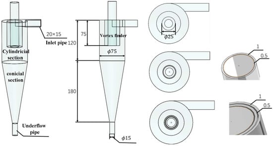
Figure 1.
Structure of the Hydrocyclone.

Table 1.
Structural Parameters of the Hydrocyclone.
2.2. Grid Generation and Boundary Condition Settings
This study employed CFD-FLUENT to conduct a numerical analysis of the flow field and particle classification performance within the hydrocyclone. Before performing numerical analysis on the physical model, mesh generation must first be implemented. Common mesh types include tetrahedral and hexahedral meshes [15,16]. While tetrahedral meshes are simple to partition, they typically offer lower computational accuracy and are usually suitable for large and irregular volumes. In contrast, hexahedral meshes, characterized by high precision and faster computation speeds, are widely used for meshing regular objects. This study adopted Fluent 22.0 for the numerical simulation of hydrocyclones, which was generally divided into two steps. Firstly, the RSM+VOF model was used to conduct numerical analysis of the internal flow field of the hydrocyclone, with the flow field balance at the inlet and outlet as the convergence criterion—the error did not exceed 2%, the residuals were less than 1 × 10⁻⁵, the number of operating steps was not less than 60,000, and the operating time was 21 h. Secondly, the RSM+Mixture model was employed for the numerical simulation of the particle phase, taking the flow balance of particles with different sizes at the inlet and outlet as the convergence condition, where the error did not exceed 2%, the operating time was 36 h, and the number of operating steps was 80,000. Therefore, this study utilized ICEM 22.0 to create a hexahedral mesh for the physical model. To capture the subtle flow near the vortex finder, the mesh was refined along the wall surface of the vortex finder, as shown in Figure 2. The number of mesh elements is a key parameter affecting computational accuracy and efficiency. Consequently, to select an appropriate number of mesh elements, a mesh independence verification was conducted, illustrated in Figure 3. Tangential velocity was adopted as the evaluation criterion; when the number of mesh elements exceeded 3.09 × 10⁵, the tangential velocity showed little variation with changes in mesh count, indicating that further increases in mesh quantity would not enhance numerical accuracy. To save computational time, this study selected 3.2 × 10⁵ hexahedral mesh elements as the computing domain units. The convergence condition is based on balancing the inflow and outflow rates.
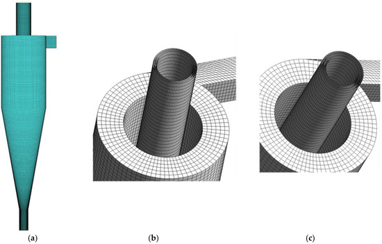
Figure 2.
Meshes. (a) Global Mesh Generation. (b) Double-Vortex Finder Mesh. (c) Triple-Vortex Finder Mesh.
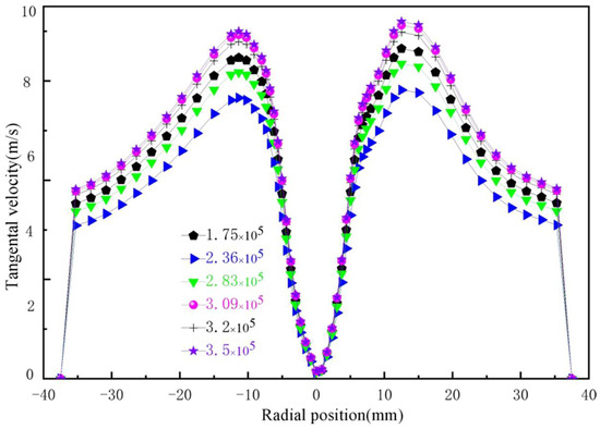
Figure 3.
Grid Independence Verification.
This study employed Fluent 2024 for numerical simulations, using water as the continuous phase and quartz sand (with a density of approximately 2650 kg/m3) as the particulate phase. The rationale behind this selection is that the density of quartz sand closely resembles that of the particles commonly encountered in industrial scenarios such as mineral processing and water treatment (e.g., ore fragments and siliceous impurities), accurately reflecting the balance between the centrifugal forces and resistances experienced by particles during actual separation processes. Additionally, quartz sand possesses high hardness and strong chemical inertness, making it resistant to changes in particle size and density due to wear or dissolution during the simulation, thus ensuring data stability. The mass concentration was set at 17.5% (corresponding to a volume concentration of approximately 7.5%), and the particle size distribution of the quartz sand is presented in Table 2.
Table 2.
Particle Size and Volume Fraction.
The inlet of the hydrocyclone is set as a velocity inlet, with both the water phase and particle phase inlet velocities configured at “5 m/s.” The spigot and all overflow outlets are designated as pressure outlets, and the air recirculation coefficient is set to 1, ensuring that air enters through at least one outlet. The pressure-velocity coupling employs the SIMPLE algorithm, while the wall of the hydrocyclone is treated with a no-slip boundary condition. The pressure equation utilizes the PRESTO scheme, and the momentum equations are solved using the third-order accurate QUICK format. The volume fraction of the two phases is discretized using the Geo-Reconstruct method to more accurately track the gas–liquid interface, while the remaining equations use a first-order upwind scheme. The time step for transient simulations is set at 1 × 10⁻⁴ s, with flow balance at the inlet and outlet serving as the convergence criterion, ensuring that the error does not exceed 2.5%.
2.3. Model Validation
It is quite necessary to validate the established mathematical model before the present numerical simulation. In 1988, Hsieh experimentally investigated the flow field in the hydrocyclone with a diameter of 75 mm (φ75 mm) and obtained the detailed data of the flow field [17]. The Mixture model was then validated based on Delgadillo’s experiment [18], in which the quartz sand with a solid-phase concentration of 10.47% was used as the feeding material. The particle separation efficiency was validated under the same solid-phase concentration condition.
3. Results and Discussion
3.1. Static Pressure
The total pressure within a hydrocyclone primarily consists of static pressure and dynamic pressure. Dynamic pressure is the pressure that reflects the fluid flow phenomena; it acts only in the direction of the fluid’s advance and has a positive value, which can be simply understood as the pressure that occurs after the fluid flows within the pipeline. Static pressure refers to the pressure acting perpendicular to the surface of the fluid and is one of the main pressures during fluid motion [19,20,21]. It significantly influences the energy conversion within the hydrocyclone and operational energy consumption. The effect of the number of internal vortex finders on static pressure in the ZX plane is shown in Figure 4, where the static pressure is highest at the wall and gradually decreases towards the center, becoming negative at the center. This situation is a result of the conversion between pressure energy and kinetic energy and is also the primary reason for the formation of the air core. The influence of the number of internal vortex finders on the characteristics of static pressure variation is relatively minor. To describe the variation in static pressure at a microscopic level, the distributions along three diameters at Z = 70 mm, 150 mm, and 230 mm are examined, as shown in Figure 5. The overall static pressure exhibits a “V”-shaped variation, which is consistent with the static pressure changes in the ZX plane. In the vicinity of the spigot area (Z = 70 mm), the structure with triple vortex finders maintains a higher static pressure. As the axial distance increases, the static pressure of the dual and triple vortex finder structures gradually falls below that of the single vortex finder structure. This variation not only ensures sufficient pressure energy for particles within the conical section but also facilitates the stable discharge of particles from the overflow, thereby enhancing the grading accuracy of the particles.
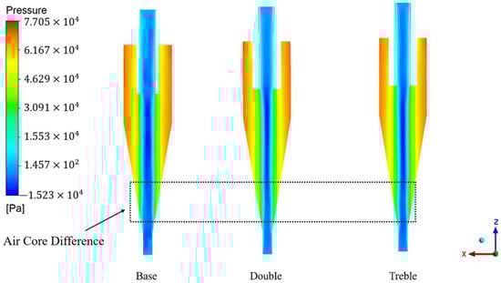
Figure 4.
Distribution of Static Pressure in the ZX Plane.
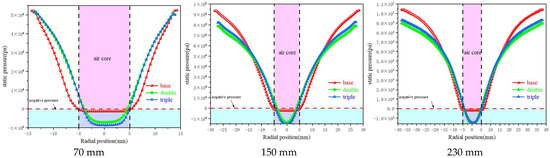
Figure 5.
Distribution of Static Pressure along the Characteristic Line.
3.2. Tangential Velocity
Particle separation in a hydrocyclone primarily relies on centrifugal force and pressure gradient force. When the centrifugal force exceeds the pressure gradient force, particles migrate outward and are discharged from the spigot; conversely, they are discharged from the overflow outlet if the centrifugal force is lower, ultimately achieving particle classification [22,23,24]. The tangential velocity is the highest velocity in the velocity field of the hydrocyclone, as it is the main source of the centrifugal force required for the particles. According to the centripetal force formula: it is evident that larger particles experience substantially greater centrifugal force than smaller particles. When the tangential velocity is excessively high, smaller particles can easily enter the outer swirling flow, leading to a finer underflow; conversely, when the tangential velocity is too low, particles struggle to be classified. Thus, an appropriate tangential velocity is one of the critical factors influencing the precision of particle classification. The effect of the number of internal vortex finders on tangential velocity is shown in Figure 6, where the tangential velocity gradually increases along the wall towards a specific position in the center. This change is opposite to that of static pressure, which is consistent with Bernoulli’s equation. The maximum tangential velocity occurs in the central region between the vortex finder and the spigot, commonly referred to as the trajectory of maximum tangential velocity. The influence of the number of internal vortex finders on tangential velocity in the ZX plane is relatively minor. To describe the morphological changes in tangential velocity at a microscopic level, the distributions along diameters at Z = 70 mm, 150 mm, and 230 mm are examined, as shown in Figure 7. The overall tangential velocity exhibits an “M”-shaped variation, which corresponds to a composite vortex distribution. As the number of internal vortex finders increases, the tangential velocity gradually decreases, showing significantly better symmetry compared to the single vortex finder structure. This indicates that the internal flow field of the multi-vortex finder structure is more stable, which benefits the enhancement of particle classification precision. Although the tangential velocity values in the multi-vortex finder structure show a slight reduction, this does not affect normal particle classification. Additionally, it lowers the probability of tangential vortices occurring, thereby facilitating the regular migration of particles.
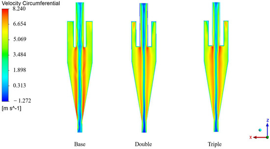
Figure 6.
Distribution of Tangential Velocity in the ZX Plane.
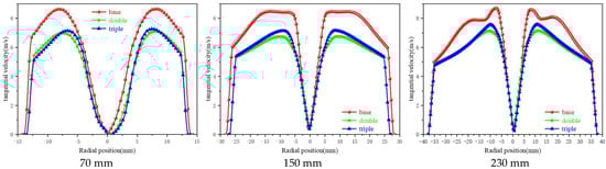
Figure 7.
Distribution of Tangential Velocity along the Characteristic Line.
3.3. Axial Velocity
Axial velocity is another important velocity component within the velocity field. The magnitude of axial velocity directly affects the residence time of particles in the hydrocyclone and determines the split ratio (the split ratio refers to the ratio of underflow flow rate to overflow flow rate) [25,26,27]. The effect of the number of internal vortex finders on axial velocity is illustrated in Figure 8. Axial velocity can be positive or negative, with the default direction of internal swirling flow (upward) taken as positive and external swirling flow (downward) considered negative. Additionally, the axial velocity reaches its maximum value in the central region, with a positive direction, indicating that the gas flow direction within the air core is from the spigot to the overflow outlet. At the diameters of Z = 150 mm and Z = 230 mm, the axial velocity of the structure with triple vortex finders is at its minimum. The reduced axial velocity leads to a longer residence time for particles within the hydrocyclone, which is beneficial for the precise classification of fine particles.
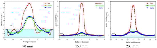
Figure 8.
Distribution of Axial Velocity along the Characteristic Line.
When the direction of axial velocity changes, there will inevitably be points where the velocity is zero. Connecting all these zero points forms the zero-velocity envelope surface (LZVV), which serves as the boundary between internal swirling flow and external swirling flow. It is one of the important flow patterns during the operation of the hydrocyclone and significantly affects the classification performance of the hydrocyclone. The impact of the number of vortex finders on the LZVV is illustrated in Figure 9. The LZVV of conventional hydrocyclones is displaced outward, indicating a larger space for fine particle classification, but with a larger cut size (the particles at the LZVV position are in a state of radial force balance), resulting in reduced cutting capacity of the hydrocyclone. In comparison to conventional hydrocyclones, the LZVV of the dual and triple vortex finder structures shifts inward, enhancing the cutting capacity of the hydrocyclone. Additionally, the shape of the LZVV with triple vortex finders closely resembles that of the inner wall surface of the hydrocyclone, which is more rational. The regular variation of the LZVV indicates smoother particle movement and a more stable internal flow field.
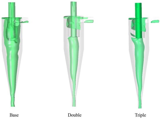
Figure 9.
Effect of the Number of Vortex Finders on the LZVV.
3.4. Radial Velocity
Radial velocity is the lowest velocity within the hydrocyclone and is highly susceptible to external influences. Therefore, employing numerical analysis to investigate the variations in radial velocity within the hydrocyclone is one of the reliable methods. Although radial velocity does not directly affect the classification performance of the hydrocyclone, like tangential and axial velocities, it has a significant impact on the formation of the radial particle layer [28]. The influence of the number of vortex finders on radial velocity is shown in Figure 10. It can be observed that axial velocity exhibits both positive and negative characteristics. This phenomenon arises from the following reasons: in the external swirling flow, the fluid experiences strong centrifugal force due to high rotation speeds, pushing heavy-phase particles toward the walls of the hydrocyclone while also driving the surrounding fluid toward the walls. The internal swirling flow is located in the central region of the hydrocyclone and is influenced by the “compression” from the external swirling flow and the pressure gradient, causing particles near the walls to replenish toward the center to maintain the circulation of the internal swirling flow. This also explains the alternating positive and negative characteristics of the radial velocity. In conventional structures, the variation of radial velocity is more frequent and exhibits poor symmetry, indicating instability in the internal flow field. In contrast, the radial velocity symmetry of dual and triple vortex finder structures is better. At diameters Z = 150 mm and Z = 230 mm, the radial velocity in dual and triple vortex finder structures is greater than that in conventional structures. The larger radial velocity reduces the time taken for particles to form a particle layer in the radial direction, minimizing particle displacement and thereby enhancing the classification accuracy of the hydrocyclone.
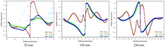
Figure 10.
Distribution of Radial Velocity along the Characteristic Line.
3.5. Air Core
The air core is one of the unique characteristics of a hydrocyclone. During the process of converting pressure energy into kinetic energy, the pressure energy gradually decreases. When the pressure drops below the atmospheric pressure, air is drawn into the center of the hydrocyclone, forming an air core. Although the air core does not participate in particle classification, it occupies the separation space, compressing surrounding particles and indirectly affecting the classification accuracy. The influence of the number of internal vortex finders on the air core is shown in Figure 11. The air core does not have a fixed shape, and its diameter changes frequently, reflecting the vigorous fluid compression on the air. This also indirectly demonstrates that the internal environment of the hydrocyclone is a high turbulence field. The effect of the internal vortex finders on the diameter of the air core is illustrated in Figure 11. The conventional vortex finder structure exhibits a peak at Z = 260 mm (approximately two-thirds the distance from the bottom of the vortex finder), which is commonly referred to as the “throat-like” bulge. This phenomenon arises from multiple convergences in that region. The dual-wall and triple-wall vortex finders effectively eliminate this phenomenon, reducing the impact of convergence on particle movement. Moreover, the air core diameter in the dual and triple vortex finder structures is significantly smaller than that in conventional hydrocyclones, occupying a smaller separation space. Under the same operating conditions, this results in a larger particle separation space, facilitating more thorough classification of the particles.

Figure 11.
Effect of the Number of Vortex Finders on the Air core.
3.6. Efficiency Curve
The efficiency curve is one of the important evaluation factors of the classification performance of standard hydrocyclones, representing the recovery rate of particles of different sizes in the underflow [29,30,31]. The influence of the number of vortex finders on classification efficiency is illustrated in Figure 12. As the particle size increases, the recovery rate of particles in the underflow continues to rise, which is consistent with the classification principle of the hydrocyclone. To provide a more comprehensive description of the classification performance of the hydrocyclone, the cut size and steepness index are introduced. The cut size refers to the particle size corresponding to a classification efficiency of 50%, usually denoted as d50. A smaller particle size indicates a stronger cutting ability of the hydrocyclone. The steepness index refers to the slope of the efficiency curve at d50, typically expressed as the ratio of d25 to d75. A higher value indicates greater classification accuracy. The influence of the number of vortex finders on the cut size and steepness index is shown in Figure 13, where the hydrocyclone with triple vortex finders exhibits the smallest cut size and the highest steepness index, indicating that it has the strongest cutting ability and the highest classification accuracy.
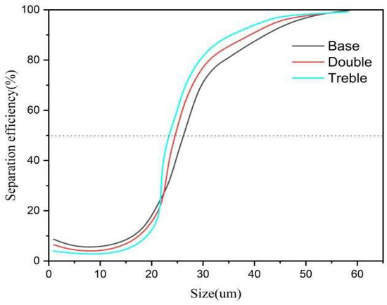
Figure 12.
Numerical Simulation of Classification Efficiency.
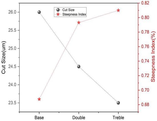
Figure 13.
Cut Size and Steepness Index.
4. Experimental Investigation and Numerical-Experimental Consistency Validation
To explore the classification behavior of particles in the hydrocyclone and to verify the accuracy of the numerical analysis, laboratory experiments were conducted. First, suitable experimental materials were selected, maintaining the average particle size of around 25 µm for the fine particles, with the specific particle size distribution shown in Table 3. An experimental setup was constructed, as illustrated in Figure 14. The experimental setup mainly consists of a high-pressure plunger pump, a variable frequency drive, a feed cylinder, a pressure gauge, a flow meter, and various piping systems. To maintain the continuity of the experiments, the material from the overflow pipe and the underflow material were fed back into the feed cylinder to form a closed-loop circulation. After ensuring the system operates normally, samples of the feed, overflow, and underflow materials were collected separately for each of the three vortex finder configurations (single, double, triple). For each configuration, three parallel experiments were conducted under the same operating conditions (inlet velocity 5 m/s, mass concentration 17.5%), and the final results were averaged to reduce random errors (relative standard deviation < 3%). The final measurement results were averaged to reduce experimental errors. Finally, a high-precision Malvern laser particle size analyzer was used for measuring particle size to obtain the classification performance of the hydrocyclone.
Table 3.
Material particle size composition.
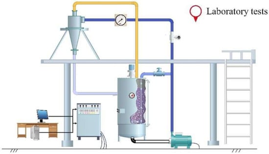
Figure 14.
Experimental Setup.
Once the material collection is complete, the classification efficiency curve is generated using the principle of particle size balance and experimental methods. The specific formula is as follows:
where represents classification efficiency, represents the computed grade content in the feed, represents the computed grade content in the overflow, and represents the computed grade content in the underflow.
The influence of the number of vortex finders on the classification efficiency of the hydrocyclone is illustrated as shown. From Figure 15, it can be observed that in the underflow, the structure with triple vortex finders has the lowest content of fine particles (particle size less than 10 µm), significantly improving the fine particle bypass phenomenon. As the number of vortex finders increases, the efficiency curve gradually shifts to the left, and the cutting ability gradually enhances. This change is consistent with that shown in Figure 12, confirming the accuracy of the numerical simulation.
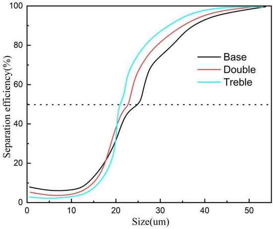
Figure 15.
Experimental Classification Efficiency.
We used the content of −20 µm fine particles in the underflow, the content of −20 µm fine particles in the overflow, as well as mass efficiency and volumetric efficiency as evaluation indicators for the classification performance of the hydrocyclone. The classification results are shown in Table 4. It can be observed that as the number of vortex finders increases, the content of −20 µm fine particles in the underflow decreases while the content in the overflow increases. The structure with triple vortex finders reduces the content of fine particles in the underflow by 4.36 percentage points compared to the single vortex finder (Base), effectively minimizing fine particle bypass. The mass efficiency improves by 18.85 percentage points compared to the single vortex finder, while volumetric efficiency does not significantly decrease. This indicates that it is possible to effectively enhance particle classification accuracy while ensuring classification efficiency.
Table 4.
Separation efficiency comparison.
5. Conclusions
- The use of a hydrocyclone with triple vortex finders can achieve higher classification accuracy for fine particles of various sizes compared to conventional methods. Additionally, it can be employed in a parallel configuration to achieve high-efficiency separation, effectively addressing the issue of low concentrate recovery rates caused by excessive grinding of qualified products.
- The pressure and velocity fields within the hydrocyclone with triple vortex finders exhibit greater stability compared to those with a single vortex finder. This results in smoother particle movement within the hydrocyclone, while the LZVV shifts inward, allowing fine particles to migrate more easily toward the inner swirling flow, thereby reducing the carryover of fine particles in the underflow. Meanwhile, the diameter of the air core is minimized, and the “throat-like” bulge within the vortex finder disappears, which reduces the impact of convergence on the particles.
- Experimental analysis indicates that the content of fine particles in the underflow structure with triple vortex finders decreased by 4.36 percentage points compared to the single vortex finder. The mass efficiency improved by 18.85 percentage points, while the volumetric efficiency did not show a significant decrease. This demonstrates that it is possible to effectively enhance particle classification accuracy while ensuring classification efficiency.
Author Contributions
Data curation, F.L., G.H., B.M., Y.F. and J.L.; Investigation, C.Z. (Chaoqi Zou); Methodology, F.L., G.H., B.M., C.Z. (Chaoqi Zou), J.L., Y.F. and J.L.; Project administration, J.L., Y.W., C.Z. (Chaoqi Zou), Y.F. and J.L.; Validation, J.L., Y.W. and C.Z. (Chenglei Zhang); Writing—original draft, F.L., G.H., B.M., J.L., Y.W. and C.Z. (Chenglei Zhang); Writing—review and editing, B.M. All authors have read and agreed to the published version of the manuscript.
Funding
This work was financially supported by Shandong Province Key Research and Development Plan (Competitive Innovation Platform) Project (2025CXPT150).
Institutional Review Board Statement
Not applicable.
Informed Consent Statement
Not applicable.
Data Availability Statement
The original contributions presented in this study are included in the article. Further inquiries can be directed to the corresponding author.
Conflicts of Interest
The authors declare no conflicts of interest.
References
- Mustafa, A.K.Q. Hydrocyclone flow characteristics and measurements. Flow Meas. Instrum. 2020, 73, 101741. [Google Scholar] [CrossRef]
- Liu, P.K.; Chu, L.Y.; Wang, J.; Yu, Y.F. Enhancement of hydrocyclone classification efficiency for fine particles by introducing a volute chamber with a pre-sedimentation function. Chem. Eng. Technol. 2008, 31, 474–478. [Google Scholar] [CrossRef]
- Chu, L.Y.; Yu, W.; Wang, G.J.; Zhou, X.-T.; Chen, W.-M.; Dai, G.-Q. Enhancement of hydrocyclone separation performance by eliminating the air core. Chem. Eng. Process. 2004, 43, 1441–1448. [Google Scholar] [CrossRef]
- Liu, L.; Zhao, L.X.; Sun, Y.; Gao, S.; Jiang, M.; Jiang, M.; Rosso, D. Separation performance of hydrocyclones with medium rearrangement internals. J. Environ. Chem. Eng. 2021, 9, 105642. [Google Scholar] [CrossRef]
- Huang, A.N.; Maeda, N.; Shibata, D.; Fukasawa, T.; Yoshida, H.; Kuo, H.-P.; Fukui, K. Influence of a laminarizer at the inlet on the classification performance of a cyclone separator. Sep. Purif. Technol. 2017, 174, 408–416. [Google Scholar] [CrossRef]
- Yang, Q.; Wang, H.-L.; Liu, Y.; Li, Z.-M. Solid/liquid separation performance of hydrocyclones with different cone combinations. Sep. Purif. Technol. 2010, 74, 271–279. [Google Scholar] [CrossRef]
- Wu, Z.; Liang, Z.; Li, P.; Li, F.; Yang, H. Effect of Vortex Finder Wall Thickness on Internal Flow Field and Classification Performance in a Hydrocyclone. Separations 2025, 12, 149. [Google Scholar] [CrossRef]
- Hwang, K.J.; Chou, S.P. Designing vortex finder structure for improving the particle separation efficiency of a hydrocyclone. Sep. Purif. Technol. 2017, 172, 76–84. [Google Scholar] [CrossRef]
- Li, T.; Su, B.; Huang, Y.; Wang, Y.; Lv, W.; Xiang, M.; Li, H. Optimization of vortex finder length of the mini-hydrocyclone. Powder Technol. 2025, 465, 121262. [Google Scholar] [CrossRef]
- Amani, A.; Shamloo, A.; Vatani, P.; Ebrahimi, S. Particles Focusing and Separation by a Novel Inertial Microfluidic Device: Divergent Serpentine Microchannel. Ind. Eng. Chem. Res. 2022, 61, 152369. [Google Scholar] [CrossRef]
- Pietro, B.; Marco, M. Selective dissolution process featuring a classification device for the removal of fines in crystallization: Experiments. Ind. Eng. Chem. Res. 2021, 60, 15752–15765. [Google Scholar] [CrossRef]
- Otto, A.; Rauh, S.; Ihlenfeldt, S.; Radons, G. Stability of milling with non-uniform pitch and variable helix tools. Int. J. Adv. Manuf. Technol. 2017, 89, 2613–2625. [Google Scholar] [CrossRef]
- Insperger, T.; Stepan, G. Updated semi-discretization method for periodic delay-differential equations with discrete delay. Int. J. Numer. Methods Eng. 2004, 61, 117–141. [Google Scholar] [CrossRef]
- Zhao, B.T.; Shen, H.G.; Kang, Y.M. Development of a symmetrical spiral inlet to improve cyclone separator performance. Powder Technol. 2004, 145, 47–50. [Google Scholar] [CrossRef]
- Frausto, J.J.; Ballantyne, G.R.; Runge, K.; Powell, M.S.; Wightman, E.M.; Evans, C.L.; Gonzalez, P.; Gomez, S. The effect of screen versus cyclone classification on the mineral liberation properties of a polymetallic ore. Miner. Eng. 2021, 169, 106930. [Google Scholar] [CrossRef]
- Sun, R.; Hou, F.; Ding, Y.; Geng, K.; Yang, Q. Design and performance evaluation of soil washing on heavy metal contaminated soil by hydrocyclone. Chin. J. Environ. Eng. 2018, 12, 1208–1217. [Google Scholar]
- Hsieh, K.T.; Rajamani, K. Phenomenological model of hydrocyclone: Model development and verification for single-phase flow. Int. J. Miner. Process. 1988, 22, 223–237. [Google Scholar] [CrossRef]
- Delgadillo, J.A. Modelling of 75- and 250-mm Hydrocyclones and Exploration of Novel Designs Using Computational Fluid Dynamics. Ph.D. Thesis, The University of Utah, Salt Lake City, UT, USA, 2006. [Google Scholar]
- Li, X.; Li, D.; Zhang, G.; Lu, Z.Y. Study on real-time control of humanoid robot using EMGs. China Mech. Eng. 2006, 17, 488–492. [Google Scholar]
- Wang, G.; Li, D.; Qian, X.; Shi, Q.; Zhang, Q. Developing of a new dexterous three fingered hand. Chin. J. Mech. Eng. 1997, 33, 71–75. [Google Scholar]
- Olga, V.; Bongers, R.M.; Van, D. Functionality of i-LIMB and i-LIMB pulse hands: Case report. J. Rehabil. Res. Dev. 2013, 50, 1123–1128. [Google Scholar]
- Flores-Luna, R.I.; Dorador-González, J.; Espinosa-Bautista, A. Prosthesis analysis based on TRIZ. Key Eng. Mater. 2013, 572, 135–138. [Google Scholar] [CrossRef]
- Jacobsen, S.C.; Wood, J.E.; Knutti, D.F.; Biggers, K.B. The UTAH/M.I.T. dextrous hand: Work in progress. Int. J. Robot. Res. 1984, 3, 21–50. [Google Scholar] [CrossRef]
- Bridgwater, L.B.; Ihrke, C.A.; Diftler, M.A.; Abdallah, M.E.; Radford, N.A.; Rogers, J.M. The robonaut 2 hand-designed to do work with tools. In Proceedings of the 2012 IEEE International Conference on Robotics and Automation, St. Paul, MN, USA, 14–18 May 2012; pp. 3425–3430. [Google Scholar]
- Hands, D.; Robot, S. Developments in dextrous hands for advanced robotic applications, 2004. In Proceedings of the World Automation Congress, Seville, Spain, 28 June–1 July 2004. [Google Scholar]
- Kochan, A. Shadow delivers first hand. Ind. Robot. 2005, 32, 15–16. [Google Scholar] [CrossRef]
- Ji, L.; He, L.; Chu, K.; Kuang, S. How Particles with Sizes Close to Cut Size Affect the Multiphase Flows and Performance of Hydrocyclones. Ind. Eng. Chem. Research. 2021, 60, 18477–18489. [Google Scholar] [CrossRef]
- Hsieh, K.T. Phenomenological Model of the Hydrocyclone. Ph.D. Thesis, The University of Utah, Salt Lake City, UT, USA, 1988. [Google Scholar]
- Hou, D.; Cui, B.; Zhao, Q.; Wei, D.; Song, Z.; Feng, Y. Research on the structure of the cylindrical hydrocyclone spigot to mitigate the misplacement of particles. Powder Technol. 2021, 387, 61–71. [Google Scholar] [CrossRef]
- Vakamalla, T.R.; Mangadoddy, N. The dynamic behaviour of a large-scale 250-mm hydrocyclone: A CFD study. Asia-Pac. J. Chem. Eng. 2019, 14, e2287. [Google Scholar] [CrossRef]
- Ye, J.; Xu, Y.; Song, X.; Yu, J. Numerical modelling and multi objective optimization of the novel hydrocyclone for ultra-fine particles classification. Chem. Eng. Sci. 2019, 207, 1072–1084. [Google Scholar] [CrossRef]
Disclaimer/Publisher’s Note: The statements, opinions and data contained in all publications are solely those of the individual author(s) and contributor(s) and not of MDPI and/or the editor(s). MDPI and/or the editor(s) disclaim responsibility for any injury to people or property resulting from any ideas, methods, instructions or products referred to in the content. |
© 2025 by the authors. Licensee MDPI, Basel, Switzerland. This article is an open access article distributed under the terms and conditions of the Creative Commons Attribution (CC BY) license (https://creativecommons.org/licenses/by/4.0/).