Abstract
For reliability and safety issues of injection wells, corrosion resistance of materials used needs to be determined. Herein, representative low-cost materials, including carbon steel X70/1.8977 and low alloyed steel 1.7225, were embedded in mortar to mimic the realistic casing-mortar interface. Two types of cement were investigated: (1) Dyckerhoff Variodur commercial Portland cement, representing a highly acidic resistant cement and (2) Wollastonite, which can react with CO2 and become stable under a CO2 stream due to the carbonation process. Exposure tests were performed under 10 MPa and at 333 K in artificial aquifer fluid for up to 20 weeks, revealing crevice corrosion and uniform corrosion instead of expected pitting corrosion. To clarify the role of cement, simulated pore water was made by dispersing cement powder in aquifer fluid and used as a solution to expose steels. Surface analysis, accompanied by element mapping on exposed specimens and their cross-sections, was carried out to trace the chloride intrusion and corrosion process that followed.
Keywords:
carbon capture storage (CCS); carbon dioxide; corrosion; carbon steels; aquifer fluid; cement; casing; pitting 1. Introduction
Carbon capture and storage (CCS) is identified as a promising technology to reach the target of CO2 reduction. However, the safety issues and cost effectiveness hinder the future of CCS [1]. As a final and crucial step in the CCS process, CO2 geological storage, which is required to last for hundreds of years, needs to be ensured by a proper well integrity. Conventionally, steel tubulars and cement seals are used to prevent leakage of CO2, utilizing the very low permeability of cement (typically less than 0.1 Millidarcy). However, possible failure can still happen due to: (1) mechanical deformation of wellbore cement; (2) chemical degradation of wellbore cement due to CO2 in the form of carbonic acid; and (3) corrosion of the wellbore casing steels. Except the first one, which caused mainly by operational activities or natural stresses, the other two are in focus of corrosion research groups worldwide [2,3,4,5,6,7,8,9,10,11,12,13,14,15,16].
Although CO2 itself is not corrosive, it reacts with water in wet supercritical CO2 or CO2-saturated brine to form carbonic acid (1), which may lead to the dissolution of cementitious phases and the carbonation process of mortar (2)–(5), followed by leaching of carbonate (6) and increasing porosity and permeability, finally creating pathways through a steel surface. Upon leakage of CO2 and brine into the casing surface, corrosion processes, including localized and pitting, can occur [2,6]. This can dramatically reduce the casing performance and lifetime (Figure 1).
where, in the “[]” of Equations (4) and (5), the notation “C” stands for CaO and “S” for SiO2 after standard cement chemistry. C3.4−S2−H8 is calcium-silicate-hydrate (C-S-H), which is the binding phase in the cement, whereas SiOxOHx is an amorphous silica gel.
𝐶𝑂2 + 𝐻2𝑂 ⇌ 𝐻2𝐶𝑂3 ⇌ 𝐻+ + 𝐻𝐶𝑂3− ⇌ 2𝐻+ + 𝐶𝑂32−
𝐶𝑎(𝑂𝐻)2(𝑠) + 2𝐻+ + 𝐶𝑂32− →𝐶𝑎𝐶𝑂3(𝑠) + 2𝐻2𝑂
𝐶𝑎(𝑂𝐻)2(𝑠) + 𝐻+ + 𝐻𝐶𝑂3− →𝐶𝑎𝐶𝑂3(𝑠) + 2𝐻2𝑂
[𝐶3.4−𝑆2−𝐻8](𝑠) + 2𝐻+ + 𝐶𝑂32− →𝐶𝑎𝐶𝑂3(𝑠) +𝑆𝑖𝑂𝑥𝑂𝐻𝑥(𝑠)
[𝐶3.4−𝑆2−𝐻8](𝑠) + 𝐻+ + 𝐻𝐶𝑂3− →𝐶𝑎𝐶𝑂3(𝑠) +𝑆𝑖𝑂𝑥𝑂𝐻𝑥(𝑠)
𝐶𝑎𝐶𝑂3(𝑠) + 𝐻+ ⇌ 𝐶𝑎2+ + 𝐻𝐶𝑂3−
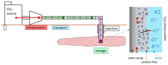
Figure 1.
Sketch of the carbon capture and storage (CCS) process and possible corrosion mechanisms happening at casing steel/cement due to CO2-brine penetration.
If the material is not compatible with the injected fluids, excessive casing corrosion will occur. A corrosion process that happened on various steels due to corrosive brine was thoroughly reported by previous researchers, revealing chloride induced pitting as a main and severe appearance form of corrosion even for some high alloyed steels [6,7,8,9,10,11]. These laboratory observations were further confirmed by field studies. Laumb et al. (2016) reported case studies in the Weyburn CO2 capture field, signifying wellbore corrosion and failure in the form of small pits to complete penetration through the steel casing [4]. The main reasons for this were the effects of injected CO2, injected fluid, formation fluid, and the corrosive environment of the perforated area. On the other hand, possible debonding of cement leading to leakage pathways along a cemented well and the effect of CO2 on the alternation of cement properties were addressed in some other studies [11,12,13,14,15]. Although problems stemming from either steel or cement are well addressed, few works have been devoted to the corrosion process that might happen at the interface of cement and casing steels upon exposure to supercritical CO2 and brine [2,3,4,16]. Thus, the present work aims to fill this gap with realistic materials and experiment conditions. It is noted that the term “mortar” instead of “cement” (as discussed above) will be used in this study to describe a mixture of cement and sands, since “cement” is a fine binding powder that is never used alone but is a component of both concrete and mortar. Since the quality of mortar is important to the wellbore integrity, in this study, a commercial system (Variodur®50 by Dyckerhoff) with high resistance to acidic environment has been chosen. Another alternative is a new emerging natural material called Wollastonite, which can react with CO2 and become stable under a CO2 stream due to the carbonation process [17,18,19,20]. Comparison tests were carried out to shed light on its merit over traditional cement.
Two representative steels, 1.8977 and 1.7225, were used to mimic casing materials and compared to high alloyed reference material 1.4562, also known as alloy 31. To mimic a realistic and highly corrosive aquifer fluid, the test solution/electrolyte was prepared according to the composition of the aggressive Northern German Basin (NGB) aquifer fluid, having a pH ~5.6 and a very high concentration of chloride (4.7 M).
2. Materials and Methods
2.1. Materials
Two representative steels, 1.8977 (comparable to X70) and 1.7225, were used to mimic casing metallic materials. 1.4562 was chosen as the reference material. Elemental composition of these steels based on optical emission spectroscopy can be found in Table 1.

Table 1.
Chemical composition with major elements 1 as the weight percent of the investigated material.
Two types of cement were chosen to be investigated in this study. The first cement was a commercial cement named Variodur®50 (Dyckerhoff AG, CEM III, according to DIN EN 197-1). The main components were CaO (53.40 wt.%), SiO2 (27.90 wt.%), Al2O3 (7.63 wt.%), and MgO (3.95 wt.%), while each of the other components (Fe2O3, K2O, SrO, ZrO, MnO, TiO2, Na2O) were less than 1 wt.%. The second cement was a natural material named Wollastonite, i.e., CaSiO3, from Alfa Aeser (calcium silicate, meta, reagent grade, <20 µm powder). The main components were SiO (50.55 wt.%) and CaO (45.95 wt.%), while each of the other components (Fe2O3, Al2O3, MgO, MnO, TiO2, K2O, and SrO) were less than 1.5 wt.%.
The synthetic aquifer fluid was prepared according to the composition of the Northern German Basin (NGB) aquifer fluid, having a pH ~5.6. The exact weight of each salt to make 5 L of test solution can be found in Table 2.

Table 2.
Chemical composition in grams of 5 L Northern German Basin (NGB) fluid.
2.2. Methods
2.2.1. Corrosion Tests in CO2 Saturated Synthetic Aquifer Fluid
A Polytetrafluoroethylene (PTFE) mold was designed to embed steel coupon in mortar (Figure 2). In the case of Variodur, the mortar was prepared according to DIN 196-7 and poured in the mold containing a steel coupon. The mold was then removed after 24 h, and the metal/mortar specimens were further hydrated in tap water for 28 days before corrosion experiments. In the case of Wollastonite, a ratio of 1 g Wollastonite mixed with 5 mL water was used to prepare the slurry, which was then filled into the mold with the steel coupon. The whole mold was then placed inside an autoclave for hardening at 333 K under 2 MPa of CO2 for 7 days.
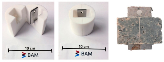
Figure 2.
A home-made PTFE mold for embedding steel coupons in mortar and (right side) a 1.8977/Variodur specimen after hydrating for 28 days. A hole was made on each steel coupon to allow hanging of the specimen inside the autoclave.
To reveal the corrosion behavior of the steel/mortar specimen, exposure tests were performed by exposing steel specimens with and without mortar at 333 K in synthetic aquifer fluid and under 10 MPa of supercritical CO2 using high-pressure stainless-steel autoclave (Parr Instruments). Before the test, the exposed steel surface was ground with carbide paper, then cleaned with ethanol and dried up to activate the metal surface. After the test, exposed specimens were then rinsed with water, ethanol, and acetone before drying to be documented.
2.2.2. Corrosion Tests in Simulated Pore-Water Mixed with Synthetic Aquifer Fluid
To mimic the worst-case scenario, where aquifer fluid penetrates mortar and reaches the metal surface, simulated pore-water was made by stirring cement powder with the electrolyte (distilled water or synthetic aquifer fluid) and was further used as a medium for exposure tests. A total of 5 g cement powder was weighed and then mixed with 500 mL electrolyte for 10 min. The pH value was then determined by a pH meter and the conductivity by a conductometer (both Knick Portamess). Both the electrolyte solutions with cement and the pure fluid were saturated with CO2 and heated to approximately 50–60 °C by a heating system. Immediately before immersing the test specimen into the solution, pH-value and conductivity were measured again.
An exposure test was performed in a glass beaker, putting it inside an autoclave, which again was placed inside a climate chamber to adjust and maintain the test temperature. The exposed specimens were then rinsed with water, ethanol, and acetone before drying to be documented.
2.2.3. Post-Characterization and Surface Analysis
To determine the corrosion rate (according to ASTM G1-03) and reveal pitting corrosion underneath the corrosion products, the specimens were then etched when needed to remove the carbonate layer. Metallographic cross-sections, including embedding in epoxy resin, cutting, and polishing, were carried out when needed to examine the interface between steel and mortar. The epoxy resin had two additives: a diluent that allowed the resin to penetrate the small pores of the mortar and a fluorescent powder (Struers EpoDye) that helped to observe the pores under UV light.
Macro-photography, three-dimensional laser scanning, and surface morphological characterization using a scanning electron microscope (SEM, VEGA3, TESCAN, Czech Republic) of exposed specimens were carried out after drying the exposed specimens. 3D-computed tomography (RayScan Technologies GmbH, Meersburg, Germany) was used to non-destructively image the pores inside the steel/mortar specimen. Chemical analysis on the cross-sectioned specimen was performed by using Energy Dispersive X-Ray (EDS, Aztec software, Oxford Instruments) to identify the elemental composition and the distribution/penetration of the aquifer fluid components and corrosion products.
3. Results and Discussion
3.1. Impact of Supercritical CO2 and Aquifer Fluid on the Corrosion Behaviour of Steel Specimens
Pitting behavior of steels due to high concentration of chloride in formation water/aquifer fluid has been thoroughly reported in previous reports [6,7,8,9,10,11]. Economical carbon steels corrode strongly in the form of uniform loss on the surface, as well as pitting. On the other hand, high alloyed steel, such as 1.4021 (X20Cr13), 1.4034 (X46Cr13), and 1.4542 (X5CrNiCuNb164), are more resistant to homogenous loss on the surface but prone to pitting; thus, it is difficult to predict their corrosion behavior over a long period of time [6]. Among the low alloyed steels, 1.7225 (known as 42CrMo4) has been proven to have better corrosion resistance than carbon steels (1.8977/X70 or 1.0582/X52) with shallower pits or localized corrosion instead of pitting [6,7]. Taking into account these previous results, in this study, carbon steel 1.8977 was compared to 1.7225 and high alloyed steel 1.4562.
Herein, to verify the additional effect of CO2 pressure on the corrosion tendency of steels, especially for pitting corrosion, exposure tests were carried out in the same synthetic aquifer fluid saturated with pure CO2 under ambient pressure and 10 MPa. After three weeks of exposition in CO2-saturated synthetic aquifer fluid at 333 K, the 1.8977 specimen showed strong pitting corrosion with a maximum pit depth of ~96 µm, while the material 1.7225, alloyed with 1% Cr, was significantly more resistant to pitting corrosion, indicated by a lower number of pits and the maximum pit depth of ~16 µm (Figure 3b). At a pressure of 10 MPa, the pitting corrosion in both materials was stronger than at ambient pressure and the pits were both deeper and wider (Figure 4). However, it is noted that the pit density in the case of specimens tested under ambient pressure was higher than at 10 MPa. A brief summary of the analyzed data is listed in Table 3.
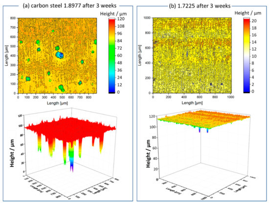
Figure 3.
3D surface scans of 3-week exposed (a) 1.8977 and (b) 1.7225 specimens in synthetic aquifer fluid at 333 K, ambient pressure, and continuous CO2 flow via glass frit.
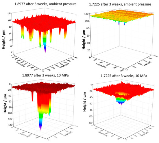
Figure 4.
3D surface scans showing effects of CO2 pressure (10 MPa versus ambient pressure) on pitting behavior of steels.

Table 3.
Pitting analysis of each steel under different testing conditions.
3.2. Impact of Supercritical CO2 and Aquifer Fluid on the Corrosion Behaviour of Steel/Mortar Specimens: Variodur Versus Wollastonite
To avoid the possible cement alternation and dissolution, either a highly acid-resistant cement or a cement that becomes stable under a CO2 stream and high saline aquifer fluid should be used [3,4,12,13,14,15,16]. In this study, commercial Variodur50 cement was chosen, since it is known to have better performance in aggressive medium, while, for the second option, natural Wollastonite was chosen, since it was proven to be able to turn into CaCO3 in a so-called carbonation process [17,18,19,20]. Despite its merit, Wollastonite did not show a good binding to the steel surface, showing mostly no or only partially hardened binding (Figure 5a,b, respectively). Thus, further optimization of extra binding materials and the hardening process are needed. The mortar made of Variodur and standard sand showed, in contrast to Wollastonite, a dense and firm binding to the steel surface. Figure 6 shows images of steel/Variodur specimens after taking it out from the mold and hydrating for 28 days. Some signs of corrosion products were found on 1.8977/Variodur and 1.7225/Variodur due to contact with oxygen, containing electrolytes, while 1.4562/Variodur did not show any changes on the metal surface. The control specimens were then embedded in an epoxy resin containing a fluorescent dye under vacuum, followed by hardening, cross-sectioning, and polishing. The whole preparation process was carried out without using water to avoid a further corrosion process that might happen on carbon steels. Pictures of embedded specimens under white light (Figure 7b) and ultraviolet light (Figure 7c) reveal a dense structure of Variodur mortar with some pores distributed inhomogenously in the matrix and some close to the steel surface. This indicates possible capillary porosity, which may lead to the intrusion of CO2-saturated fluid to the steel surface. To further image and quantify the pores, X-ray computed tomography was carried out. As can be seen in Figure 8, there were not only macro pores, as seen under UV light, but also micro pores were present. To quantify the volumetric amount of the pore, two selected areas were chosen to be measured (Figure 8). The amount of pores was 1.95 % in the case of the 1.8977/Variodur specimen and 2.33 % for 1.7225/Variodur. The standard deviation was 0.19% between all the samples (regardless of metallic materials). After 3 weeks of exposure, the amount of pores slightly increased, but so did the standard deviation (2.97 ± 0.32%). After 20 weeks, the pore volume slightly decreased again to about 2.32%. Thus, the significant trend could not be confirmed to elucidate the dissolution of cement phases and re-filling phenomenon due to carbonation, as discussed in some previous works.
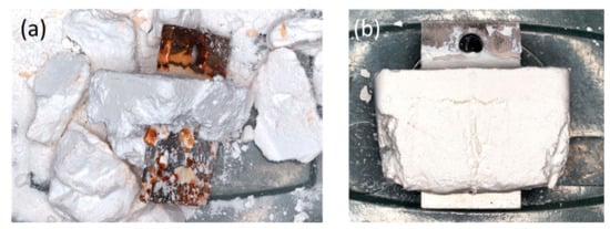
Figure 5.
Example of an incompletely cured 1.8977/Wollastonite composite specimen. (a) Wollastonite mostly not hardened; (b) Wollastonite partially hardened.

Figure 6.
Steel/Variodur specimens after hydrating for 28 days.
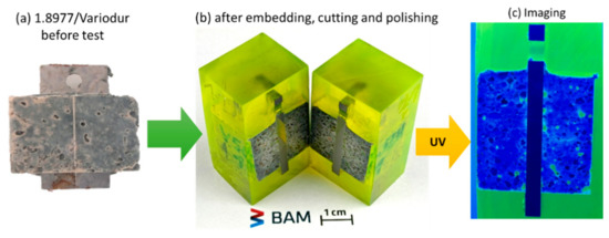
Figure 7.
Control steel/Variodur specimen (without exposing to aquifer fluid and CO2) before (a), after embedding, cutting, and polishing under white light (b) and blue light (c).
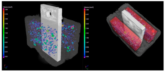
Figure 8.
Computed tomography scan of steel/Variodur specimen in pristine form (control specimen). The pores are imaged (left) and quantified in the red area (right).
As can be seen in Figure 9, in its pristine form, before exposing to aquifer fluid, the interfaces between steel and mortar, both inside and outside, even at the pore, show no sign of corrosion products, which might happen during the molding and curing process. Since carbon steels are well-known to be readily corroded when in contact with electrolyte, this result indicates the positive effect of high pH-induced solution of water-mixed cement and sand on the corrosion behavior of carbon steels.
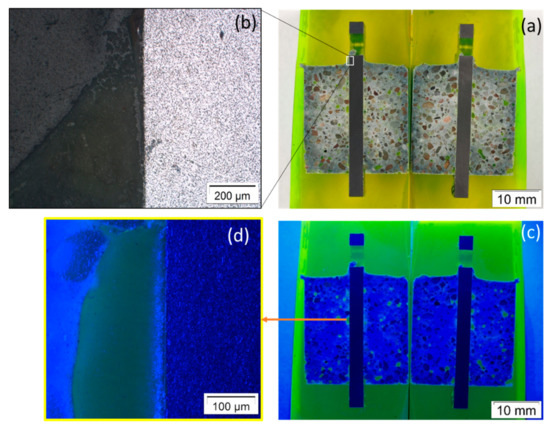
Figure 9.
Images of steel/Variodur interface in pristine form (control specimen) under (a,b) white light and (c,d) ultraviolet light.
However, Figure 10 clearly shows the corrosion process that happened at the triple point, e.g., steel/mortar in contact with electrolyte, which was somewhat similar to crevice corrosion after 3 weeks of exposure. Back-scattered electron images revealed the dissolved part of the 1.8977 surface (appeared dark) and the losing texture in the case of 1.7225 steel. It is suggested that the aquifer fluid penetrated the steel/mortar interface. The steel was then dissolved due to low pH of the CO2 saturated aquifer fluid, as can be seen clearly in the case of 1.8977/Variodur (Figure 10a). A similar process happened on 1.7225/Variodur, albeit to a lesser extent, which was in agreement with results discussed above, from exposure tests for these steels in aquifer fluid.
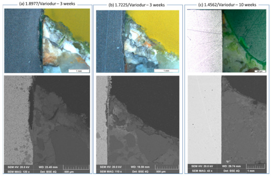
Figure 10.
Crevice corrosion at the steel/Variodur interface after exposure to 333 K, 10 MPa, and synthetic aquifer fluid. Crevice formation from the top. The upper row images were taken by a stereomicroscope, while the image (right) below was taken by back-scattered electrons in the same region of interest. In contrast to (a) 1.8977 and (b) 1.7225 (exposed for 3 weeks), (c) 1.4562 did not show any sign of crevice corrosion even after 10 weeks of exposure.
In contrast, high-alloyed steel 1.4562 did not show any sign of crevice corrosion even after 10 weeks of exposure under the same condition, indicating excellent corrosion resistance, attributed to the high content of Cr, Mo, and Ni. This image further confirmed that when no dissolution of metallic materials happens due to interacting with aquifer fluid, the casing-interface will remain well bonded. After 10 weeks, the mortar did not change its texture at this triple junction. Our finding partly differs from results by Veccia et al., in which the authors reveal no signs of degradation in perfectly bonded cement-steel interfaces but show corrosion in the not-perfectly bonded interface [12]. We found crevice corrosion in all exposed 1.8977/Variodur specimens, regardless of bonding quality. The reason for this might be very high aggressivity of the NGB aquifer fluid. This further signifies the need for corrosion testing under conditions as close as possible to the in-situ condition of the planned CO2 capture field site.
To further analyze corrosion mechanisms at the interface of steel/mortar, element mapping was carried out on both 1.8977/Variodur and 1.7225/Variodur specimens (Figure 11 and Figure 12). In both cases, Fe depletion, along with migration of Cl and Ca, were clearly observed. In the case of 1.8977/Variodur, the anodic dissolution of steel was clearly shown by a loss of Fe, creating a gap at the beginning of the crevice, followed by a gradient of Fe concentration at the end of the penetration depth. Since the synthetic aquifer fluid contained a very high concentration of CaCl2, it is expected that the Ca2+ reacted with carbonate species and precipitated in the form of CaCO3 inside this crevice, raising the concentration of Ca and O in this gap. Another possibility is the dissolution of the portlandite, followed by the carbonation process, leading to the formation of CaCO3 [12]. As a result of fluid migration into the crevice, Cl was found along the gap, indicating the pitting possibility if the test was prolonged under fluid exchange condition. Besides these crevice corrosion behaviors, it was noted that the map of Si showed a clearly defined boundary of mortar with a steel surface, showing almost no dissolution of this cementitious phase into the gap. The same mechanism was observed in the case of 1.7225/Variodur after 20 weeks of exposure. Due to a longer exposure time, chloride concentration in the crevice was significantly increased, along with Fe migration into the mortar matrix.
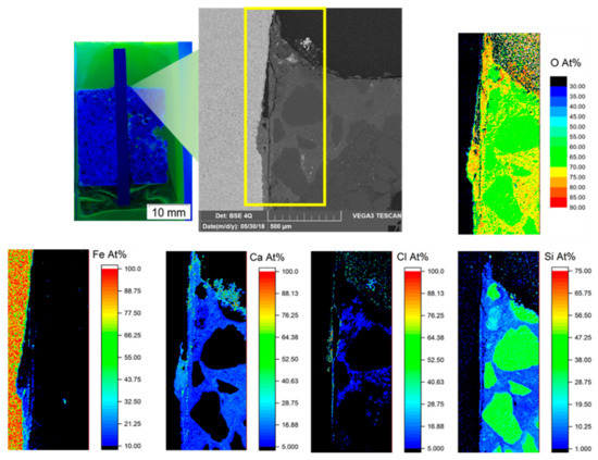
Figure 11.
Element mapping at the 1.8977/Variodur interface by EDS.

Figure 12.
EDS element mapping at the 1.7225/Variodur interface after 20 weeks of exposure to aquifer fluid under 10 MPa CO2.
3.3. Possibility of Aquifer Fluid Penetration into the Pores at the Interface of Mortar/Steel
To immobilize the corrosion products after exposure tests, the specimens were dried and embedded with epoxy resin under vacuum, allowing resin to penetrate into the pores. The fluorescent dye was mixed with epoxy to enable differentiation between these pores and other grains under a microscope. As can be seen in Figure 13a, in a pristine state, at the pore/metal interface, there were no signs of corrosion products. This was attributed to the very high pH of pore water (between 12.5 and 13.5), which induced a thin passive layer made of iron oxides (α-Fe2O3 and γ-Fe3O4), similar to passivation of reinforcing steel in concrete during the hydration process [21]. However, this passivation may be broken in the presence of chlorides at a certain concentration ratio of Cl¯/OH¯. This ratio, in turn, depends on the chloride concentration in aquifer fluid/brine and the pH range of the pore water during the contamination process [22].
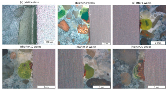
Figure 13.
Observation of corrosion products at the pores positioned at the interface between mortar and carbon steel 1.8977 surface before (a) and after (b) 3, (c) 6, (d) 10, (e) 14, and (f) 20 weeks of exposure.
In this study, the cross-sections of exposed specimens after 3, 6, 10, 14, and 20 weeks all showed the orange corrosion products at the interface of pores (appeared in light yellow and green due to fluorescent dye) with steel compared to the interface between solid grains and metal surfaces (Figure 13b–f). This suggests the intrusion of aquifer fluid into the pores, leading to the breakdown of the passive layer by increasing the concentration of chloride, along with the decrease of pH. The pH value of NGB after being saturated with CO2 at 333 K was ~3.0, and at the end of 20 weeks of exposure, it was ~5.2. The concentration of chloride did not change, since it was too high (4.7 M) at the beginning. However, it is impossible to measure pH changes as well as chloride concentration in pores at the metal–mortar interface. Thus, to shed light on what happens when aquifer fluid is mixed with available pore water at the steel-mortar contact point, further exposure tests were carried out in so-called simulated pore water using genuine cement powder instead of simplified chemical mixtures of NaOH, KOH, CaSO4.2H2O, and Ca(OH)2 [21,22].
3.4. Effect of Cement on the Corrosion Behavior of Steels at the Brine Intruded Pores
Even 20 weeks of exposure without changing the brine could not be extrapolated into the final field application. Therefore, an attempt was made to simulate the worst-case scenario, where the brine/aquifer fluid penetrated into the mortar through micro-pores and reached the steel surface. The question is whether or not the cement matrix can provide a passivation process on the steel surface so that the normal pitting process (as discussed in part 3.1) can be lessened to some extent or even completely inhibited. As shown in Figure 13, the penetration of the fluid via pores is possible; however, no pits were revealed in all cross-sections of all exposure specimens. Here, time plays a significant role. Supposedly, at the significant period of time, an increasing concentration of chloride can reach the steel surface. Thus, to mimic this final state, a simulated pore water was proposed by dispersing cement powder with aquifer fluid, while representative noncontaminated pore water was made by dispersing cement powder in pure water. This was further used as a medium to carry out static exposure tests in autoclaves at 333 K and ambient pressure of CO2.
Figure 14 provides an overview of the specimen surfaces before and after 4 weeks of exposure in NGB with and without cement. In both cases, the 1.8977 and 1.7225 specimens suffered from both uniform and pitting corrosion processes, with a large amount of carbonate salts deposition on the exposed surface. After very short etching (up to 4 s in HCl with the inhibitor, then cleaned with acetone), the precipitations could be removed, which revealed the pitting underneath. Pitting was found to be much more profound in the case of 1.8977 than that of 1.7225, which is in agreement with the results of the exposure test in NGB only. However, the maximum pit depth showed almost no change in the case of 1.7225 (28 to 31 µm) and slightly decreased in the case of 1.8977 (64 to 54 µm), with and without cement dispersed in NGB, respectively. This slightly inhibiting effect can be attributed to the increase of the pH with and without cement dispersed in NGB. NGB itself had pH around 5.6, and after being saturated with CO2, the pH decreased to 3.0. In contrast, after 10 min of stirring Variodur powder in NGB at room temperature, the solution got the pH of 9.6 due to the alkalinity of cement. Although pH was decreased significantly after being saturated with CO2 at 333 K and reached the value of 4.7 (Table 4), it was still higher than that of NGB without cement suspension. As a result of lower pH, the dissolution of metallic materials inside the pit was expected to be faster, thus deeper pits were formed.
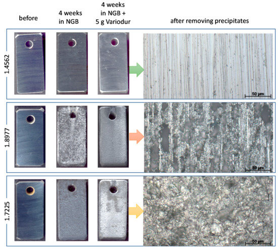
Figure 14.
Macrophotographs (left) and stereomicroscope pictures (right) of 4-week-exposed steel specimens in simulated pore water with and without mixing with aquifer fluid. The total volume of the test solution in each test was 500 mL, and 5 g of Variodur was used.

Table 4.
Effects of cement suspension on the pH of testing solutions and maximum pit depth.
As discussed above, pitting was caused mainly by aggressive high chloride concentration in NGB and not due to Variodur. This again can be proved by exposing 1.8977 in Variodur mixed in ultra-pure water (pH ~11.7 after mixing and down to ~5.7 after being saturated by CO2 at 333 K). Figure 15a shows the exposed surface with mostly uniform corrosion. The same phenomenon was found with Wollastonite (Figure 15b). The alkalinity of Wollastonite was found lower than that of Variodur based on a lower pH of the suspended water-based solution (9.7). However, after being saturated by CO2 at 333 K, the pH was comparable (~6.0). Mixing NGB with the cement induced pitting in both cases. Interestingly, bigger pits with less pit density were found in the case of Wollastonite compared to that of Variodur (Figure 15c,d, respectively). The pH-values after being saturated by CO2 at 333 K and before immersing the specimens were found to be the same in both cases, ~4.7. Thus, in this case, it is the cement’s nature that induces the difference between two types of pitting behavior. One possible reason for this is the pitting effect from silicates, the chemical component of Wollastonite. Considering this negative effect from Wollastonite, it is not recommended to use this type of cement in its pristine form. On the other hand, the results clearly demonstrate the possibility of pitting upon intrusion of aquifer fluid into pores that were located at the steel-mortar interface. The degree of pitting is expected to be depended on chloride concentration of formation water, porosity, permeability, diffusion rate, and, last but not least, exposure time.
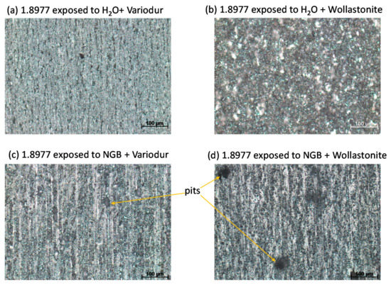
Figure 15.
Stereomicroscope images showing the effect of cement on the pitting behavior of 1.8977 in simulated pore water mixed with (c,d) and without (a,b) aquifer fluid NGB.
4. Conclusions
Carbon steel X70/1.8977, considered as the construction material for wellbores, is shown to be susceptible to pitting corrosion (up to a depth of 140 µm after 3 weeks) due to high chloride concentration in aquifer fluid. In the same testing condition, low alloyed steel 1.7225 with 1 % Cr performed better against pitting corrosion and superaustenite steel 1.4562 was pitting-resistant. Considering the casing-cement interface, two types of cement were chosen; a representative highly acid-resistant commercial Portland cement, Variodur50, and an emerging natural material, called Wollastonite, which becomes stable under CO2 due to the carbonation process. Despite its merits, Wollastonite showed unfavorable properties not only on adhesion to the metal surface during the hardening process under CO2, but also due to increasing pitting susceptibility of carbon steels. Thus, it is not further recommended for wellbore integrity in its pristine form.
Although the interface between mortar and steel is known to be passivated due to a high pH of pore water (~13), the corrosion process can happen at the exposed metal surface and process along with casing, which is somewhat similar to crevice corrosion. This happened earlier than direct pitting due to the intrusion of chlorides through capillary pores of mortar. Further testing with simulated pore water showed that pitting can occur when the brine/aquifer fluid penetrates the pores and reaches the interface of the metal-mortar, leading to the breakdown of the passive layer. It is therefore suggested that, depending on the aggressivity of the aquifer fluid, care should be taken in choosing the cement type combined with high alloyed steel to avoid crevice corrosion, as well as pitting in the far future of wellbore.
Author Contributions
Conceptualization, L.Q.H, D.B., R.B., and M.B.; methodology, E.B., B.N.S., and L.Q.H.; investigation, E.B., B.N.S., and L.Q.H.; writing—original draft preparation, L.Q.H.; writing—review and editing, R.B. and D.B.; project administration, D.B. All authors have read and agreed to the published version of the manuscript.
Funding
This research was funded by the German Federal Ministry for Economic Affairs and Energy, grant number FKZ 03ET7031C, in Project CLUSTER.
Acknowledgments
The authors would like to acknowledge Michaela Buchheim, Heike Strehlau, Sibylle Engel, and Christoph Peetz for technical support and cement preparation and curing: Andreas Neumann, Kristoff Svennson (Martin-Luther-Universität Halle Wittenberg, Germany), C. Stephan-Scherb, and Axel Kranzmann for advising students, discussion, and hints.
Conflicts of Interest
The authors declare no conflict of interest.
References
- Andersen, S.T. Risk, Liability, and Economic Issues with Long-Term CO2 Storage-A Review. Nat. Resour. Res. 2017, 26, 89–112. [Google Scholar] [CrossRef]
- Choi, Y.-S.; Young, D.; Něsíc, S.; Gray, L.G.S. Wellbore integrity and corrosion of carbon steel in CO2 geologic storage environments: A literature review. Int. J. Greenh. Gas Control 2013, 16S, S70–S77. [Google Scholar] [CrossRef]
- Carey, J.W. Geochemistry of Wellbore Integrity in CO2 Sequestration: Portland Cement-Steel-Brine-CO2 Interactions. Rev. Mineral. Geochem. 2013, 77, 505–539. [Google Scholar] [CrossRef]
- Laumb, J.D.; Glazewaki, K.A.; Hamling, J.A.; Azenkeng, A.; Watson, T.L. Wellbore corrosion and failure assessment for CO2 EOR and storage: Two case studies in the Weyburn field. Int. J. Greenh. Gas Control 2016, 54, 479–489. [Google Scholar] [CrossRef]
- Carey, J.W.; Wigand, M.; Chipera, S.J.; WoldeGabriel, G.; Pawar, R.; Lichtner, P.C.; Wehner, S.C.; Raines, M.A.; Guthrie, G.D. Analysis and performance of oil well cement with 30 years of CO2 exposure from the SACROC Unit, West Texas, USA. Int. J. Greenh. Gas Control 2007, 1, 75–85. [Google Scholar] [CrossRef]
- Yevtushenko, O.; Bettge, D.; Bohraus, S.; Bäßler, R.; Pfennig, A.; Kranzmann, A. Corrosion behavior of steels for CO2 injection. Process. Saf. Environ. Prot. 2014, 92, 108–118. [Google Scholar] [CrossRef]
- Pfennig, A.; Bäßler, R. Effect of CO2 on the stability of steels with 1% and 13% Cr in saline water. Corros. Sci. 2009, 51, 931–940. [Google Scholar] [CrossRef]
- Pfennig, A.; Zastrow, P.; Kranzmann, A. Influence of heat treatment on the corrosion behaviour of stainless steels during CO2-sequestration into saline aquifer. Int. J. Greenh. Gas Control 2013, 15, 213–224. [Google Scholar] [CrossRef]
- Pfennig, A.; Kranzmann, A. Effects of Saline Aquifer Water on the Corrosion Behaviour of Injection Pipe Steels 1.4034 and 1.7225 during Exposure to CO2 Environment. Energy Procedia 2009, 1, 3023–3029. [Google Scholar] [CrossRef][Green Version]
- Yang, Z.; Kan, B.; Li, J.; Su, Y.; Qiao, L.; Volinsky, A.A. Pitting Initiation and Propagation of X70 Pipeline Steel Exposed to Chloride-Containing Environments. Materials 2017, 10, 1076. [Google Scholar] [CrossRef]
- Pfennig, A.; Kranzmann, A. Effect of CO2 and pressure on the stability of steels with different amounts of chromium in saline water. Corros. Sci. 2012, 65, 441–452. [Google Scholar] [CrossRef]
- Vecchia, F.D.; dos Santos, V.H.J.M.; Schütz, M.K.; Ponzi, G.G.D.; Stepanha, A.S.D.G.E.; Malfatti, C.D.F.; Costa, E.M.D. Wellbore integrity in a saline aquifer: Experimental steel-cement interface degradation under supercritical CO2 conditions representative of Brazil’s Parana basin. Int. J. Greenh. Gas Control 2020, 98, 103077. [Google Scholar] [CrossRef]
- Lecampion, B.; Quesada, D.; Loizzo, M.; Bunger, A.; Kear, J.; Deremble, L.; Desroches, J. Interface debonding as a controlling mechanism for loss of well integrity: Importance for CO2 injector wells. Energy Procedia 2011, 4, 5219–5226. [Google Scholar] [CrossRef]
- Vrålstad, T.; Saasen, A.; Fjær, E.; Øia, T.; Ytrehus, J.D.; Khalifeh, M. Plug & abandonment of offshore wells: Ensuring long-term well integrity and cost-efficiency. J. Pet. Sci. Eng. 2019, 173, 478–491. [Google Scholar]
- Liteanu, E.; Spiers, C.J.; Peach, C.J. Failure behaviour wellbore cement in the presence of water and supercritical CO2. Energy Procedia 2009, 1, 3553–3560. [Google Scholar] [CrossRef]
- Wolterbeek, T.K.T.; Raoof, A. Meter-Scale Reactive Transport Modeling of CO2-Rich Fluid Flow along Debonded Wellbore Casing-Cement Interfaces. Environ. Sci. Technol. 2018, 52, 3786–3795. [Google Scholar] [CrossRef] [PubMed]
- Huijgen, W.J.J.; Witkamp, G.-J.; Comans, R.N.J. Mechanisms of aqueous Wollastonite carbonation as a possible CO2 sequestration process. Chem. Eng. Sci. 2006, 61, 4242–4251. [Google Scholar] [CrossRef]
- Svensson, K.; Neumann, A.; Menezes, F.F.; Lempp, C.; Pöllmann, H. Carbonation of Natural Wollastonite at Non-Ambient Conditions Relevant for CCS-the Possible Use as Cementitious Material in Wellbores. Appl. Sci. 2019, 9, 1259. [Google Scholar] [CrossRef]
- Svensson, K.; Neumann, A.; Menezes, F.F.; Lempp, C.; Pöllmann, H. The Conversion of Wollastonite to CaCO3 Considering Its Use for CCS Application as Cementitious Material. Appl. Sci. 2018, 8, 304. [Google Scholar] [CrossRef]
- Svensson, K.; Neumann, A.; Pöllmann, H.; Menezes, F.; Lempp, C. Curing by carbonatisation of Wollastonite. GDCh-Conf. Bauchem. 2017, 52, 80–83. [Google Scholar]
- Andrade, C.; Merino, P.; Nóvoa, X.R.; Pérez, M.C.; Soler, L. Passivation of Reinforcing Steel in Concrete. Mater. Sci. Forum 1995, 192–194, 891–898. [Google Scholar] [CrossRef]
- Garcés, P.; Sáez, A.; Andreu, C.G.; Andrade, C. The Influence of the Ratio [Cl−]/[OH−] on the Corrosion Rate of Reinforcing Steel in Neutral and Acid Solutions. Mater. Sci. Forum 1995, 192, 907. [Google Scholar] [CrossRef]
Publisher’s Note: MDPI stays neutral with regard to jurisdictional claims in published maps and institutional affiliations. |
© 2021 by the authors. Licensee MDPI, Basel, Switzerland. This article is an open access article distributed under the terms and conditions of the Creative Commons Attribution (CC BY) license (http://creativecommons.org/licenses/by/4.0/).