Article

Numerical Simulation of Axial Vortex in a Centrifugal Pump as Turbine with S-Blade Impeller

School of Energy and Power Engineering, Lanzhou University of Technology, Lanzhou 730050, China
*
Author to whom correspondence should be addressed.
Processes 2020, 8(9), 1192; https://doi.org/10.3390/pr8091192
Submission received: 18 August 2020 / Revised: 10 September 2020 / Accepted: 11 September 2020 / Published: 20 September 2020

Abstract

:
Pump as turbines (PATs) are widely applied for recovering the dissipated energy of high-pressure fluids in several hydraulic energy resources. When a centrifugal pump operates as turbine, the large axial vortex occurs usually within the impeller flow passages. In view of the structure and evolution of the vortex, and its effect on pressure fluctuation and energy conversion of the machine, a PAT with specific-speed 9.1 was analyzed based on detached eddy simulation (DES), and the results showed that vortices generated at the impeller inlet region, and the size and position of detected vortices, were fixed as the impeller rotated. However, the swirling strength of vortex cores changed periodically with double rotational frequency. The influence of vortices on pressure fluctuation of PAT was relatively obvious, deteriorating the operating stability of the machine evidently. In addition, the power loss near impeller inlet region was obviously heavy as the impact of large axial vortices, which was much more serious in low flow rate conditions. The results are helpful to realize the flow field of PAT and are instructive for blade optimization design.

1. Introduction

In recent decades, pump as turbine (PAT) has drawn increasing attention in energy recovery systems where a high-pressure water source exists. With a pump operating as turbine, the direction of flow and rotation are opposite. For pump, energy is supplied to the fluid via a rotating shaft, as shown in Figure 1a, it is a energy absorbing device. For PAT, energy is extracted from the fluid and output via the rotating shaft, as shown in Figure 1b, it is a energy producing device. Compared with a conventional hydraulic turbine, PAT is simple, inexpensive, easy to maintain, readily available worldwide, and has a short capital payback period. It is an attractive solution for micro-hydro power with capacity below 100 kW [1]. It would be economical to use PAT, recovering the dissipated energy of high-pressure fluids in several hydraulic energy resources, such as water distribution network (WDN) [2,3,4,5], sea water reverse osmosis (SWRO) [6], chemical processes [7], nature falls [8], etc.
Although there is a wide application of PAT, the selection of a proper pump operating as turbine is particularly challenging. Many selection techniques have been published so far, while researchers have tested their models on few pumps and recorded deviations in the order of ±10~20% [9]. PAT may not have optimum or favorable flow behavior since pumps are usually not designed for turbine operation. The mismatch between turbine flow parameters and pump geometry may affect the stability of flow performance [10]. In addition, PATs have poor part-load performances [11,12]. Many researchers have presented the optimization of the turbine mode performance for overcoming these challenges. All mentioned issues above require a detailed understanding of the internal flow mechanism of PAT, which is important and imperative to predict the performances of PAT, as well as improve its efficiency and operating stability.
Computational fluid dynamics (CFDs) were adopted extensively in many earlier research studies to investigate the flow behavior of PAT. A detailed analysis of the turbulence flow structure of a pump and its reverse mode were performed by Pascoa et al. [13]. Singh and Nestmann [14] revealed the wakes and the corresponding losses (flow separation) at the inlet and exit of a PAT impeller. Yang et al. [15] discussed the velocity distribution and hydraulic losses of PAT with different blade wrap angles. Ardizzon and Pavesi [11] researched the effect of relative through-flow and eddy vortex on flow behavior in PAT impellers and established the optimum incidence angle in outward- and inward-flow impellers. Zhang et al. [16] presented a numerical simulation study that the reverse flow causes a great deal of vortex in impellers. Stanbli et al. [17] studied the instability of PAT during start-up process using numerical-based method. Zobeiri et al. [18] investigated the rotor–stator interactions in turbine mode of a pump and presented the pressure fluctuation in stator flow channels. Singh and Nestmann [9] analyzed the flow condition in different flow zones of PAT and concluded the hydraulic loss of each flow zone. Simão et al. [19,20] investigated the hydrodynamic flow behavior of centrifugal PAT to better understand the energy recovery system behavior and to reach the best efficiency operation conditions. Additionally, collaborative design of rotor and stator of PAT have been concerned to improve its efficiency recently [21,22].
The PATs have poor hydraulic performances usually as the pump manufactures do not pay attention to the performances of a pump in reverse operation. As a consequence, low efficiency and instability have been found generally due to the poor flow conditions of vortices, secondary flow, and pressure fluctuation. In this research, the flow behavior of PAT was simulated by the CFD method. The structure and evolution of the large axial vortex in impeller channels were revealed, and its impact on pressure fluctuation and power losses was observed. The results can be expected to be a support for the optimization design of PAT.

2. Theoretical Model of Vortex

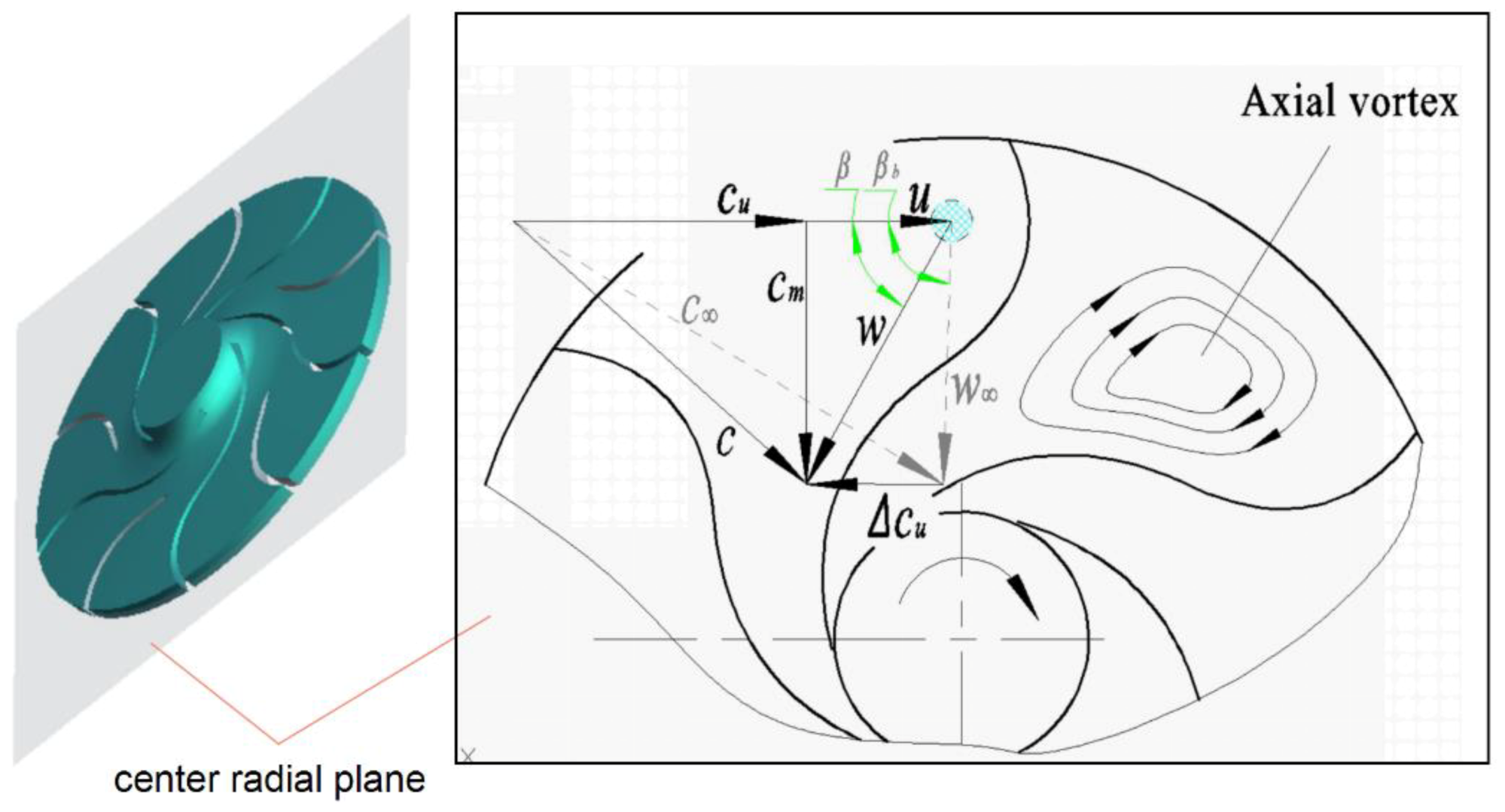
For PAT, the slip phenomenon occurs inevitably in flow passages caused by finite blades. Due to the finite blades with certain thickness of PAT, the fluid in the flow passages is guided weakly, and subsequently a slip velocity Δcu is generated, as shown in Figure 2 (where u is the peripheral velocity of impeller, w is relative velocity, c is absolute velocity, cm and cu are the meridian and peripheral components of absolute velocity, respectively, Δcu is slip velocity, β is relative flow angle and βb is the blade angle, the subscript ∞ represents infinite blades). As a consequence, the large axial vortices induced reasonably. In part-load operation, this phenomenon is much more serious on account of the non-optimum incoming flow.
In recent decades, various vortex identification methods, including closed or spiral path lines, minimum local pressure, vorticity magnitude, etc., have been used to interpret vortical structures in instantaneous flow fields [23]. The vorticity magnitude is widely applied in qualifying the intensity of vortices, and the swirling strength has been adopted—usually to qualify the vorticity magnitude.
For a random element of vortex flow, the velocity gradient tensor dij can be described as
[ d i j ] = [ v r v c r v c i ] [ λ r 0 0 0 λ c r λ c i 0 λ c i λ c r ] [ v r v c r v c i ] 1
where vr, vcr, and vci represent the axial, radial, and tangential components of the element velocity, respectively. The velocity gradient tensor dij exists one real eigenvalue λr and two conjugated complex eigenvalues λcr ± λci. The swirling strength is the imaginary part of the complex eigenvalues of the velocity gradient tensor, λci; it is positive if and only if the discriminant is positive and its value represents the strength of swirling motion around local centers. The greater the absolute value of the swirling strength, the stronger the internal circulation of fluid.

3. Numerical Simulation

3.1. Numerical Method

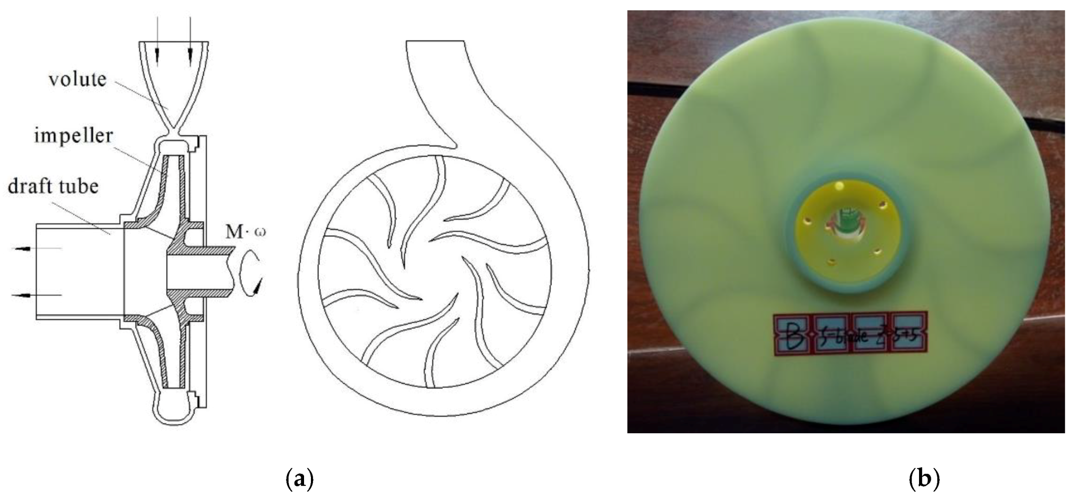
A modified PAT with specific speed (nQ1/2/H3/4, where n is rotational speed, Q is flow rate, and H is head) 9.1 was selected for numerical simulation, and the hydraulic parameters were 50 m for head and 50 m3/h for flow rate with the rotational speed 1500 r/min. The flow zones consisted of volute, impeller, and draft tube as shown in Figure 3. The main geometrical parameters were shown in Table 1.
The numerical simulation was performed by means of the Navier–Stokes equation with an appropriate turbulence model. The Reynolds Averaged Navier-Stokes (RANS) turbulence model is not appropriate for the unsteady flow prediction, while a fully-resolved Large Eddy Simulation (LES) is almost unfeasible nowadays [24]. Recently, the Detached Eddy Simulation (DES) showed the superiority of the prediction of unsteady flow phenomenon in studies by Magnoli and Schilling [25]. DES can be described as a hybrid RANS-LES turbulence modeling approach and can be applied in a numerical simulation of rotor–stator interaction, inter-blade vortices and vortex rope successfully. It is acting as a Sub-Grid-Scale (SGS) model of LES in regions where the grid resolution is fine enough to resolve turbulent structures, while in other regions the model is used as a pure RANS model [26]. It features the advantages of a less refined grid near the wall, as well as the memory requirements of a computer. DES can be explicitly presented in the Spalart–Allmaras (SA) kε model or Shear Stress Transport (SST) model.
In the present work, the CFX (17.0, ANSYS, Pittsburgh, PA, USA, 2016) was adopted for the solution of 3D Navier–Stokes equations due to its characteristics of robust and fast convergence [15]. Steady simulations were achieved using the RNG kε model and the results were applied as the initial value of transient analysis, the SA-DES turbulence model was applied for transient simulations.
The one equation SA-DES model can be described as
v ˜ t + u v ˜ = 1 σ R e [ ( ( v + v ˜ ) v ˜ ) + c b 2 | v ˜ | 2 ] + c b 1 S ˜ v ˜ c w 1 f w R e ( v ˜ d D E S ) 2
where v ˜ is a destruction term for the eddy viscosity, which is proportional to ( v ˜ / d ) 2 , where d is the distance to the closest wall, Re is Reynolds number. The second and last terms on the right side of the equation are the product term and destruction term, respectively. When balanced with the production term, the eddy viscosity is adjusted to scale with the local deformation rate S and d: v ˜ S d 2 . In the Smagorinsky model, the sub-grid-scale (SGS) eddy viscosity scales with S and the grid spacing Δ: μ S G S S Δ 2 . Thus, the SA model turns into the SGS model when d is replaced by a length proportional to Δ.
If we replace d in the SA destruction term with d ˜ , described as
d ˜ = min ( d , C D E S Δ )
then the model is an SA turbulence model when d Δ , while an SGS model when d Δ .
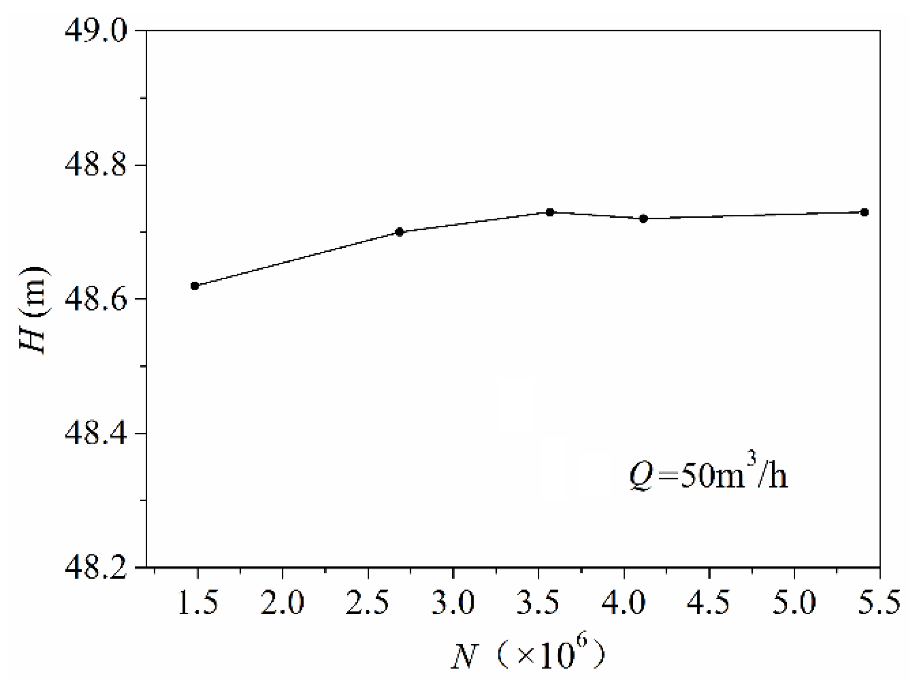
Since the SA-DES model does not require any wall functions, the mesh that is close to the wall surface must be designed to accurately predict the hydrodynamic force; hence, the high-aspect-ratio cells near the wall have been generated [27]. The mesh of the fluid domain was generated using ICEM-CFD (17.0, ANSYS, Pittsburgh, PA, USA, 2016) as its advantage of a well-adapted and efficient hexahedral grid was applied for meshing, as shown in Figure 4. The length of the inlet and outlet pipes was extended to eliminate the influence of back flow. The grid convergence and grid independence tests were performed, and the results showed that the head–flow rate curve became stable as the elements of mesh over 3,612,548, as shown in Figure 5. Therefore, the final element numbers of the volute, impeller, and draft tube were 865,260, 3,007,154, and 243,200, respectively.
The boundary condition of the inlet was the total pressure with an initial value of 0.5 MPa, and the outlet was the flow rate with an initial value of 50 m3/h for design condition; the rotational speed of the impeller was fixed with 1500 r/min. The fluid was the normal water with a temperature of 20 °C, all the wall surfaces were adiabatic, and the roughness was set to 50 μm. To obtain reasonable results, the proper selection of time steps is of great importance. It is suggested that time steps for a runner rotation of 0.5–5° could provide useful information for the flow field under transients [28]. Hence, the time steps in this study were 3.3 × 10⁻⁴ s, corresponding to 3° of the impeller rotational angle. The max coefficient loop of convergence control was 40, and the residual target of the convergence criteria was 10−5. The total time of the duration data was 0.4 s corresponding to 10 rotor revolutions and the last four revolution data were analyzed.
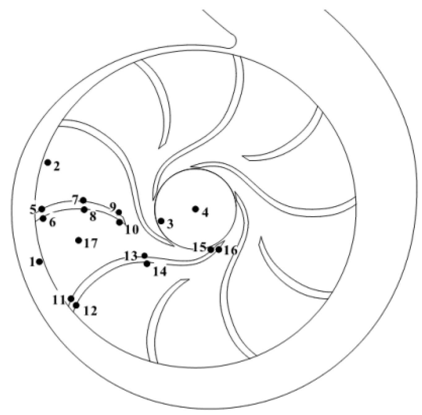
For revealing the vortex structure and pressure fluctuation in PAT flow channels, 17 monitoring points were set in the middle plane of PAT, as shown in Figure 6. Point 1 was set in the gap between volute and impeller, point 2 and 3 next to the inlet and outlet of impeller, respectively, point 4 was in center of impeller outlet, points 5, 7, 9 were on the suction profile of the short blade, while 6, 8, 10 were on the pressure side, points 11, 13, 15 were on the suction profile of the long blade, while 12, 14, 16 were on the pressure profile, point 17 was set in the flow channel.

3.2. Verification of Numerical Method

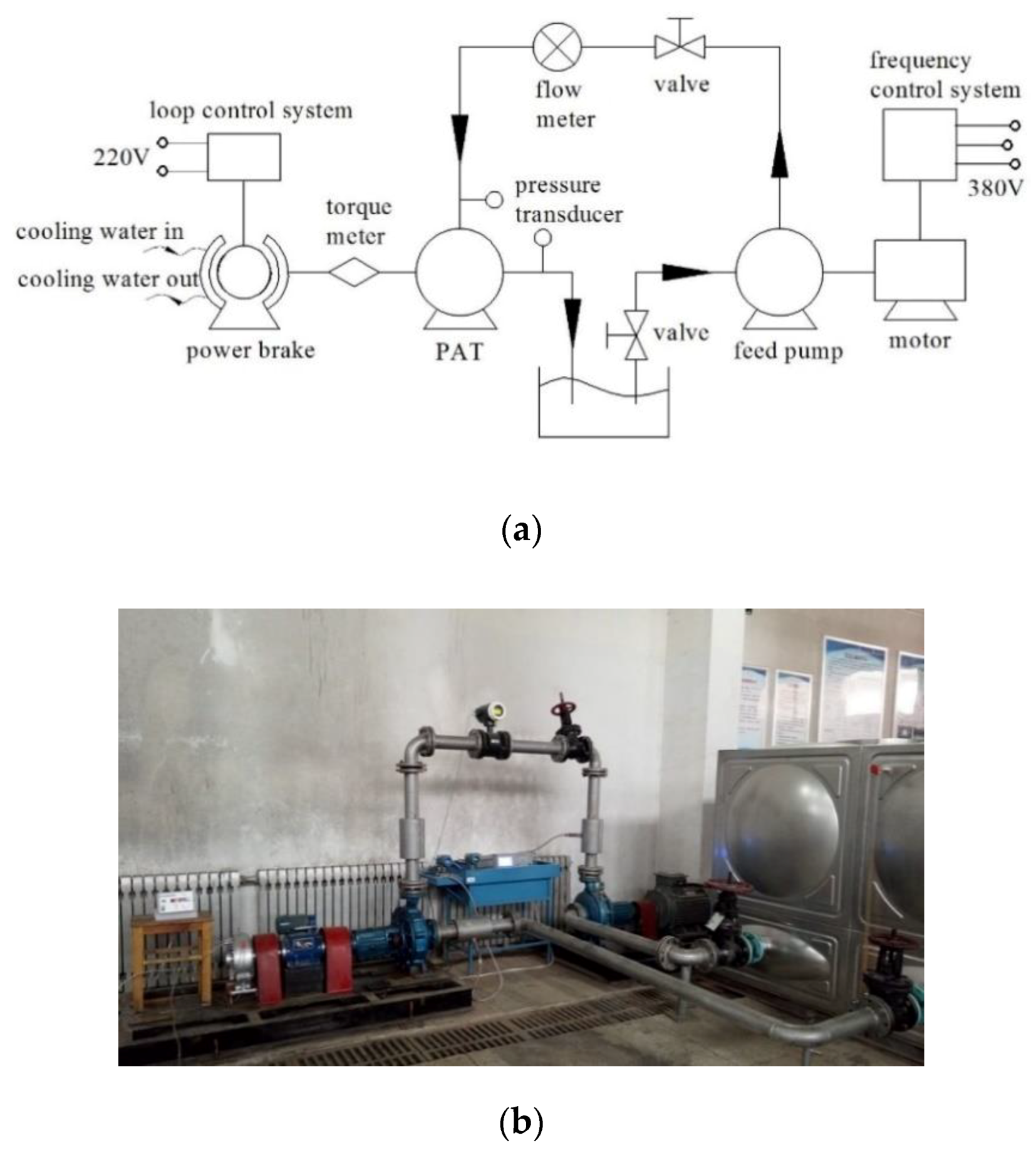
In this section, the numerical method was validated by the experimental results. A test rig was established for the hydraulic performance experiment of PAT. The test rig was composed by water supply, PAT, and energy dissipation sections as shown in Figure 7. A feed pump was installed to provide the head and flow rate for PAT. A magnetic power brake was equipped to balance the output power, and a loop control system was used to adjust the torque of output shaft. A flow meter was equipped at the inlet pipe of PAT for measuring the flow rate, and two pressure transducers were installed at the PAT inlet and outlet for measuring pressure. For measuring the torque and rotational speed of PAT, a torque meter was set at shaft. The head, flow rate, power and efficiency of PAT could be obtained after all parameters were measured.
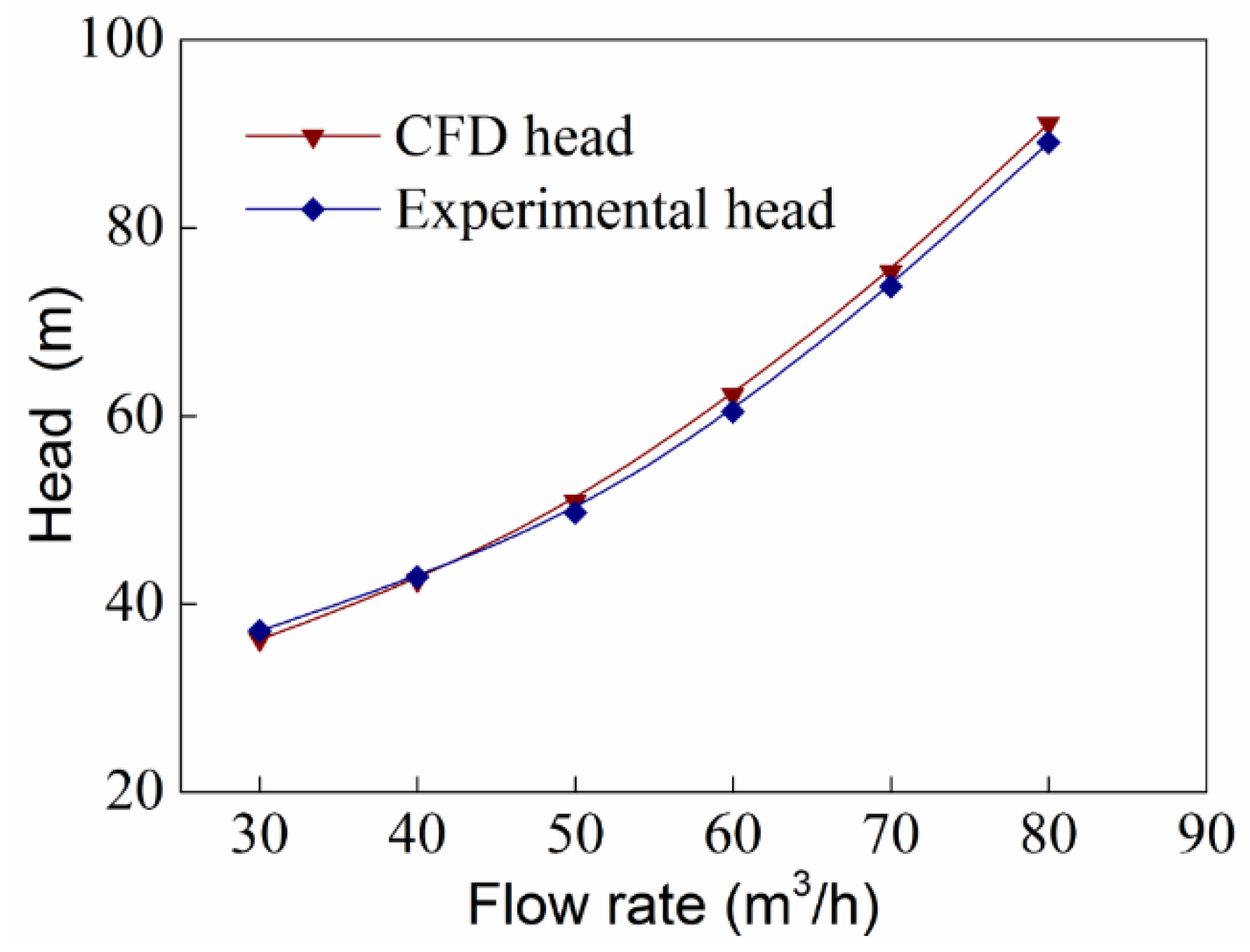
The selected PAT was tested and the hydraulic performance curves by experimental and numerical methods were illustrated in Figure 8. It can be found that the numerical head is in good coincidence with the experimental results. In consequence, it is reasonable to believe that the employed numerical method is accurate, and it can be applied in performance predictions of PAT.

4. Results and Discussion

4.1. Vortex Information in Flow Channels

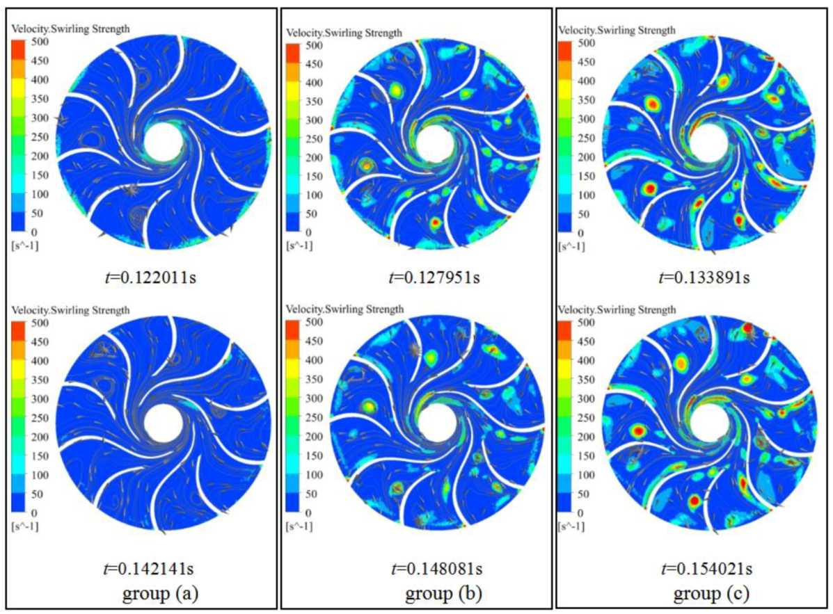
For PAT, large axial vortices were derived in impeller flow channels even at the best efficiency point (BEP), as shown in Figure 9. It can be seen that the streamline was disordered near the suction surfaces of the impeller inlet where the large axial vortices were induced. It can be clearly observed that the vortices were more legible on short blade surfaces. Furthermore, the size and position of detected vortices were invariant with rotor rotating, and apparently, these were stable.
The swirling strength contour of detected vortices during one rotating cycle was displayed in Figure 9. It can be seen that although the vortex size and position were stable, the swirling strength changed with rotation of the impeller. In the first half of the rotating cycle, the swirling strength was minimum (0~50 s−1) at 0.122011 s, intensified to maximum (450~500 s−1) at 0.133891 s, and weakened to minimum (0~50 s−1) again at 0.142141 s. The revolution of the vortex swirling strength in the second half of the cycle was the same as the first half. The vortices information was extremely similar at 0.122011 s and 0.142141 s, 0.127951 s and 0.148081 s, as well as 0.133891 s and 0.154021 s. It can be found that the time steps of each working point are 0.2 s approximately for the three groups (group a, b, and c, as shown in Figure 9), that is half the time of per rotating cycle (0.4 s) for PAT. In other words, the swirling strength of the vortex develops periodically with two times the rotating frequency.

4.2. Pressure Fluctuation of Vortex

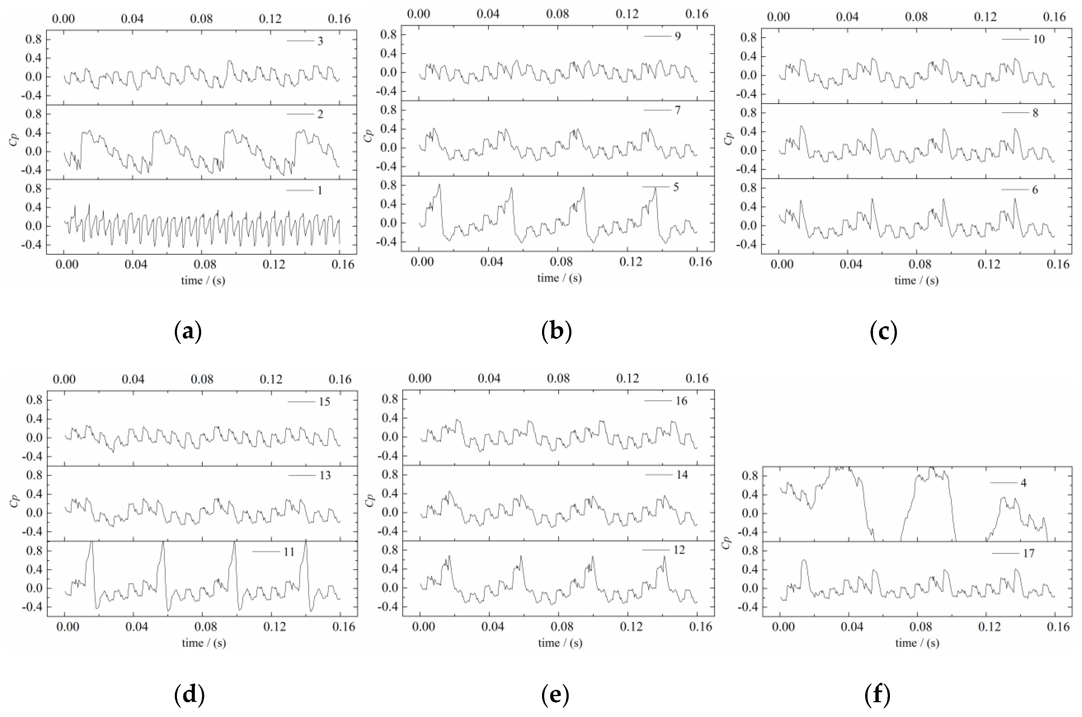
The pressure fluctuation could be produced due to the vortices with twofold rotating frequency. In order to reveal the pressure fluctuation characteristics of PAT, transient numerical simulation was performed, and results of the 17 monitoring points are given in Figure 10. Where the vertical coordinates Cp is pressure coefficient, it can be described as
C p = p i p ¯ 0.5 ρ u 1 2
where pi denotes the transient pressure of monitoring point (Pa), p ¯ is the average pressure (Pa), ρ is the density of fluid (kg/m3), and u1 is the peripheral velocity of impeller inlet (m/s).
The pressure of point 1 fluctuated 10 times in a rotating cycle visibly, which was caused by the blade–volute interaction; as the point was set in the gap between the rotor and volute, it was not related to the axial vortex obviously. Point 4 could not be related to the axial vortex as well because it was set in the draft tube that was far away from the vortex regions. The pressure fluctuation at other points showed that the leading periodical impulse was related to the rotor–stator interaction. However, it was no reason to neglect the correlation between the subordinate periodical impulse and axial vortex.
Figure 11 showed the pressure fluctuation images with frequency range, which was received by fast Fourier transform (FFT) from Figure 9. For easily understanding, the horizontal axis was the ratio of frequency (f/fn), where fn denoted the rotating frequency of the rotor.
It can be seen that the leading pressure fluctuation of the monitoring points occurred at 1 f/fn, 5 f/fn, 10 f/fn, and 20 f/fn. Obviously, this related to the rotor–stator interaction. Pressure fluctuation at 1 f/fn caused by the rotor–tongue interaction, at 5 f/fn, 10 f/fn, 20 f/fn caused by blade–tongue interaction (the impeller equipped with 5 long blades and 5 short blades). Therefore, the main factor of pressure fluctuation was the rotor–stator interaction.
However, the subordinate pressure fluctuation at 2 f/fn was found in points 2, 5, 6, 11, 12, and 17. It was obvious, especially in points 5 and 11 as marked with dashed circle in Figure 10, as mentioned earlier, that the large axial vortices were derived in these regions usually. Consequently, it was reasonable to declare that the subordinate pressure fluctuation was related to axial vortices in impeller channels, which deteriorated the operating stability of the machine evidently.

4.3. Power Losses Caused by Vortex

The large axial vortices provide subordinate contribution to the pressure fluctuation of PAT. More importantly, this might cause entropy generation in the flow field, and therefore, the power loss produced inevitably. In this section, the power losses caused by axial vortices were analyzed.
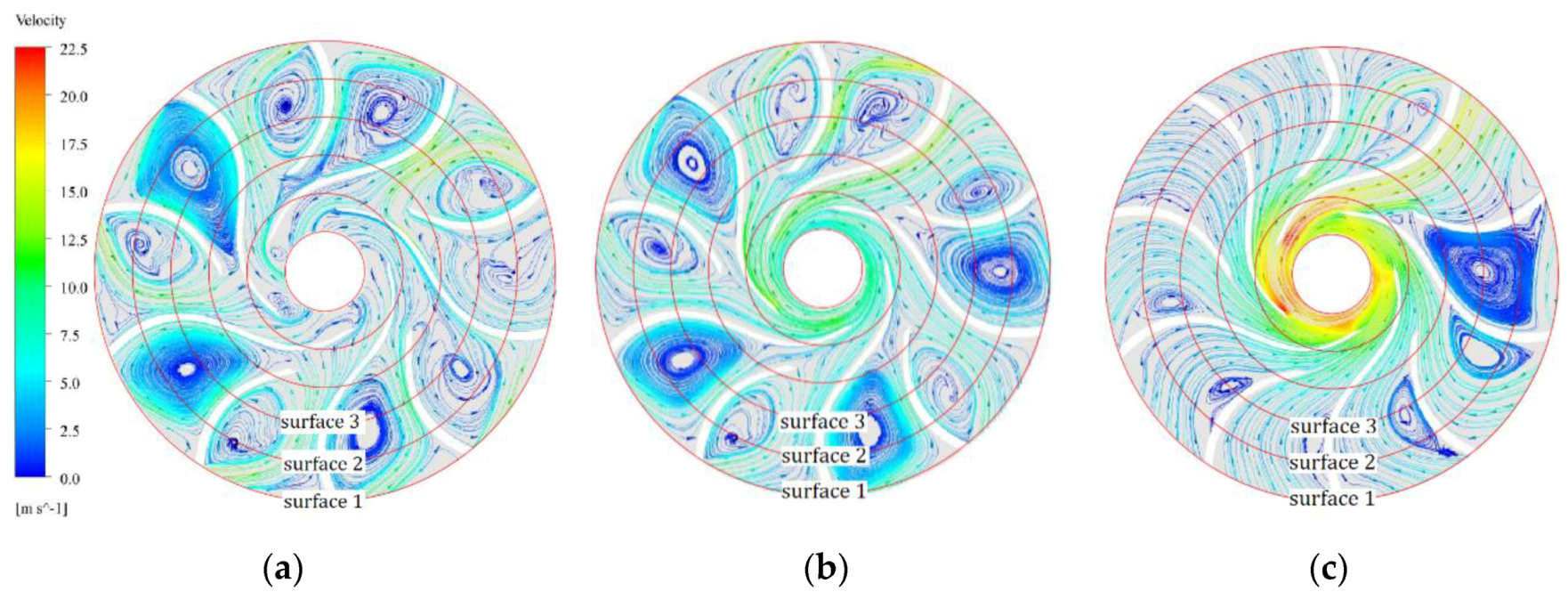
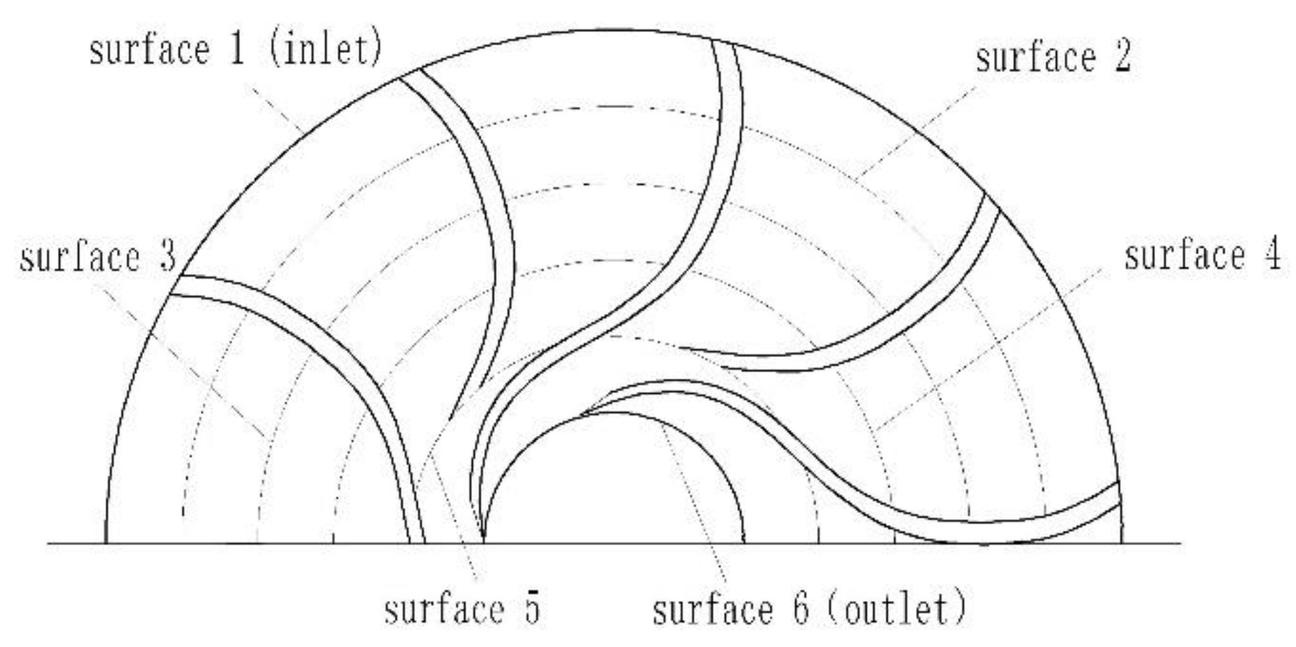
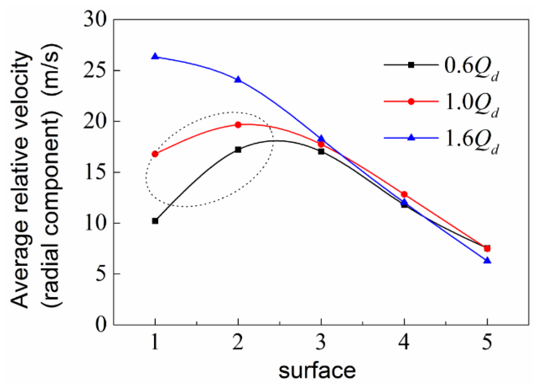
Flow distortion have been detected in the impeller that was caused by axial vortices, where a wake region has been found near the impeller inlet, it was significant especially for 0.6 Qd and 1.0 Qd (Qd is design flow rate), as shown in Figure 12. As a consequence, a low-pressure zone appeared near the impeller inlet, and the relative velocity no longer distributed alongside the blade surfaces. In order to reveal the effect of axial vortices on performance characteristics of PAT, six monitoring cylindrical surfaces in the impeller were created as shown in Figure 13. Figure 14 was the distribution of the average relative velocity (radial component) in the impeller, and Figure 15 was the average pressure at each cylindrical surface. It can be seen that the average relative velocity (radial component) and pressure curves decreased gradually along the flow direction in the impeller channels for 1.6 Qd; however, a local decline of the curves appeared at surface 1 and 2 for 0.6 Qd and 1.0 Qd. As shown in Figure 12, the streamline of 1.6 Qd was uniform, and very tiny axial vortices were detected in the flow channels. However, large axial vortices can be found near the impeller inlet at 0.6 Qd and 1.0 Qd; this was much more serious for low flow rates. It can be seen from Figure 12 that the region from surface 1 to surface 3 was worse affected by axial vortices for the low flow rates that reasonably responded to the local decline of the average relative velocity and pressure.
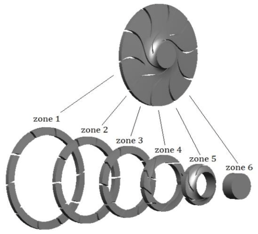
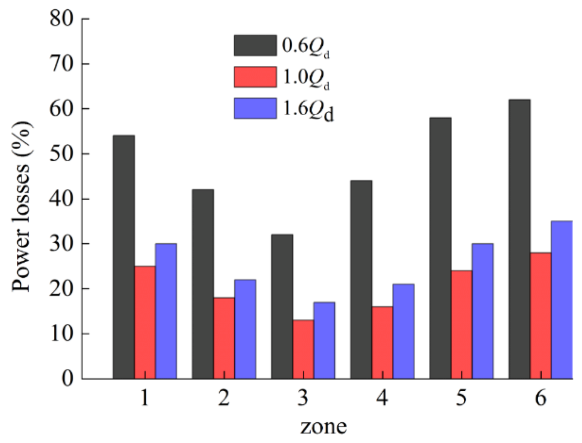
As the axial vortices were generated, power losses were raised inevitably. To study the power losses caused by vortices, the flow domain in the impeller was divided into six zones (Figure 16), and power losses of each zone were calculated.
For any zone i, when the boundary condition with a pressure inlet and flow rate outlet are given, while rotating speed is fixed, the theoretical power (fluid power) and actual power (shaft power of PAT) can be obtained by numerical simulation. The theoretical power can be described as
p ( i , i + 1 ) = ρ g Q H ( i , i + 1 )
where ρ is the fluid density, g is the gravitational acceleration, H(i,,i+1) is the fluid head of zone i, and Q is the flow rate. The shaft power of PAT is
p ( i , i + 1 ) = M ( i , i + 1 ) ω
where M(i,i+1) is the torque of zone i, while ω is the angular speed of the impeller. Then, the relative power losses of zone i are
f ( i , i + 1 ) = 1 p ( i , i + 1 ) p ( i , i + 1 )
As the numerical simulation did not consider the leakage and frictional losses of PAT, Equation (7) can be considered as relative power losses of zone i.
Figure 17 presented the power losses of each zone for 0.6 Qd, 1.0 Qd, 1.6 Qd, respectively. It can be seen that the power losses of zone 1 and 2 (the inlet region of the impeller) were higher distinctly than zone 3 and 4. As mentioned earlier, the large axial vortices occurred in this region usually, and caused the reduction in energy conversion of PAT. What calls for special attention was that the power losses of zone 5 and 6 were higher than zone 3 and 4 as well, which was related to the vortices in the draft tube to a great extent, and it deserved further research in the future.
It can be concluded also that the power losses were heaved significantly in low flow rates, which was related to the large axial vortices. As mentioned above, large axial vortices can be found near impeller inlets usually and are much more serious for low flow rates. Thus, it was believed that power losses would be induced by the large axial vortices within flow passages, and it should be considered in the design and optimization process, especially in low flow rates.

5. Conclusions

In this study, the flow behavior of a centrifugal PAT with specific speed 9.1 was researched by a verified CFD method. The large axial vortices were derived in impeller flow channels due to the slip and poor match between flow and blades. The size and position of the vortices were stable apparently. However, the swirling strength developed periodically with 2fn (fn is the rotating frequency of PAT).
The pressure fluctuation can be found in PAT. The leading pressure fluctuation was caused by the rotor–stator interaction, while the subordinate fluctuation was related to axial vortices in impeller channels, which deteriorated the operating stability of the machine evidently.
The power losses were induced by the large axial vortices in the impeller flow channels, and this phenomenon was much more serious in the low flow rate operation. This should be considered in the design and optimization process, especially in low flow rates.
Nevertheless, the feature of large axial vortices within PAT impeller channels deserved further research in detail based on more PATs. The influence of the rotation, geometry of the blades, entropy variation of the large axial vortex and efficiency of the PAT should be discussed deeply, especially in the pump–turbine transition processes.

Author Contributions

X.W.: Conceptualization, Methodology, Formal Analysis, Investigation, Writing. K.K.: Software, Data Curation. Z.W.: Resources, Data Curation. J.Y.: Validation. All authors have read and agreed to the published version of the manuscript.

Funding

This research was funded by the Nature Science Foundation of China (51569013), Industry Support and Guidance Plan of Colleges in Gansu (2020C-20), and the Article Processing Charge (APC) was funded by Outstanding Young Scientists Support Program of Lanzhou University of Technology (LUT).

Conflicts of Interest

The authors declare no potential conflicts of interests with respect to the research, authorship, and/or publication of this article.

References

  1. Giosio, D.R.; Henderson, A.D.; Waiker, J.M.; Brandner, P.A.; Sargison, J.E.; Gautam, P. Design and performance evaluation of pump-as-turbine micro-hydro test facility with incorporated inlet flow control. Renew. Energy 2015, 78, 1–6. [Google Scholar] [CrossRef]
  2. Lydon, T.; Coughlan, P.; McNabola, A. Pump-as-turbine: Characterization as an energy recovery device for the water distribution network. J. Hydraul. Eng. 2017, 143, 04017020.1–04017020.10. [Google Scholar] [CrossRef]
  3. Ramos, H.; Borga, A. Pumps as turbines: An unconventional solution to energy production. Urban Water 1999, 1, 261–263. [Google Scholar] [CrossRef]
  4. Rossi, M.; Nigro, A.; Pisaturo, G.R.; Renzi, M. Technical and economic analysis of Pumps-as-Turbines (PaTs) used in an Italian Water Distribution Network (WDN) for electrical energy production. Energy Procedia 2019, 158, 117–122. [Google Scholar] [CrossRef]
  5. Alberizzi, J.C.; Renzi, M.; Righetti, M.; Pisaturo, G.R.; Rossi, M. Speed and pressure controls of pumps-as-turbines installed in branch of water-distribution network subjected to highly variable flow rates. Energies 2019, 12, 4738. [Google Scholar] [CrossRef] [Green Version]
  6. Mohameda, E.S.; Papakakisa, G.; Mathioulakisb, E. The effect of hydraulic energy recovery in a small sea water reverse osmosis desalination system; experimental and economical evaluation. Desalination 2005, 184, 241–246. [Google Scholar] [CrossRef]
  7. Van Antwerpen, H.J.; Greyvenstein, G.P. Use of turbines for simultaneous pressure regulation and recovery in secondary cooling water systems in deep mines. Energy Convers. Manag. 2005, 46, 563–575. [Google Scholar] [CrossRef]
  8. Wang, X.H.; Yang, J.H.; Xia, Z.T.; Hao, Y.; Cheng, X.R. Effect of Velocity Slip on Head Prediction for Centrifugal Pumps as Turbines. Math. Probl. Eng. 2019, 2019, 5431047. [Google Scholar] [CrossRef] [Green Version]
  9. Singh, P.; Nestmann, F. An optimization routine on a prediction and selection model for the turbine. Exp. Therm. Fluid Sci. 2010, 34, 152–164. [Google Scholar] [CrossRef]
  10. Su, X.H.; Huang, S.; Zhang, X.J.; Yang, S.S. Numerical research on unsteady flow rate characteristics of pump as turbine. Renew. Energy 2016, 94, 488–495. [Google Scholar] [CrossRef]
  11. Ardizzon, G.; Pavesi, G. Optimum incidence angle in centrifugal pumps and radial inflow turbines. Proc. Inst. Mech. Eng. Part A J. Power Energy 1998, 212, 97–107. [Google Scholar] [CrossRef]
  12. Singh, P. Optimization of Internal Hydraulics and of System Design for Pumps as Turbines with Field Implementation and Evaluation. Ph.D. Thesis, University of Karlsruhe, Karlsruhe, Germany, 2005. [Google Scholar]
  13. Pascoa, J.C.; Silva, F.J.; Pinheiro, J.S.; Martins, D.J. Accuracy details in realistic CFD modeling of an industrial centrifugal pump in direct and reverse modes. J. Therm. Sci. 2010 19, 491–499. [CrossRef]
  14. Singh, P.; Nestmann, F. Internal hydraulic analysis of impeller rounding in centrifugal pumps as turbines. Exp. Therm. Fluid Sci. 2011, 35, 121–134. [Google Scholar] [CrossRef]
  15. Yang, S.S.; Kong, F.Y.; Chen, H.; Su, X.H. Effects of blade wrap angle influencing a pump as turbine. J. Fluids Eng. 2012, 134, 061102–061109. [Google Scholar] [CrossRef]
  16. Zhang, S.; Shi, Q.; Zhang, K. Flow behavior analysis of reversible pump-turbine in “S” characteristic operating zone. In Proceedings of the IOP Conferences Series: Earth and Environmental Science, Beijing, China, 19–23 August 2012; Volume 15, p. 032045. [Google Scholar]
  17. Staubli, T.; Senn, F.; Sallaberger, M. Instability of Pump-Turbines during Start-up in Turbine Mode. 2008. Available online: http://xueshu.baidu.com/usercenter/paper/show?paperid=97f4d4701a82fd4c1510fe74f46d3c6c&site=xueshu_se (accessed on 13 February 2020).
  18. Zobeiri, A.; Kueny, J.L.; Farhat, M.; Avellan, F. Pump-turbine rotor-stator interactions in generating mode: Pressure fluctuation in distributor channel. In Proceedings of the 23rd IAHR Symposium on Hydraulic Machinery and Systems, Yokohama, Japan, 17–21 October 2006. [Google Scholar]
  19. Simão, M.; Pérez-Sanchez, M.; Carravetta, A.; Ramos, H.M. Flow Conditions for PATs Operating in Parallel: Experimental and Numerical Analyses. Energies 2019, 12, 901. [Google Scholar] [CrossRef] [Green Version]
  20. Simão, M.; Pérez-Sanchez, M.; Carravetta, A.; Lopez-Jimenez, P.; Ramos, H.M. Velocities in a Centrifugal PAT Operation: Experiments and CFD Analyses. Fluids 2018, 3, 3. [Google Scholar] [CrossRef] [Green Version]
  21. Barrio, R.; Fernandez, J.; Blanco, E. Performance characteristics and internal flow patterns in a reverse-running pump-turbine. Proc. Inst. Mech. Eng. Part C J. Mech. Eng. Sci. 2012, 226, 695–708. [Google Scholar] [CrossRef]
  22. Shi, F.; Tsukamoto, H. Numerical study of pressure fluctuations caused by impeller-diffuser interaction in s diffuser pump stage. J. Fluids Eng. 2001, 123, 466–474. [Google Scholar] [CrossRef]
  23. Zang, Z.P.; Gao, F.P.; Cui, J.S. Physical modeling and swirling strength analysis of vortex shedding from near-bed piggyback pipelines. Appl. Ocean Res. 2013, 40, 50–59. [Google Scholar] [CrossRef] [Green Version]
  24. Krappel, T.; Kuhlmann, H.; Kirschner, O. Validation of an IDDES-type turbulence model and application to a Francis pump turbine flow simulation in comparison with experimental results. Int. J. Heat Fluid Flow 2015, 55, 167–179. [Google Scholar] [CrossRef]
  25. Magnoli, M.V.; Schilling, R. Numerical simulation of pressure pulsations in Francis turbines. In Advances in Hydroinformatics. Springer Hydrogeology; Gourbesville, P., Cunge, J., Caignaert, G., Eds.; Springer: Singapore, 2013; pp. 389–403. [Google Scholar]
  26. Masterov, M.V.; Baltussen, W.M.; Kuipers, J. Numerical simulation of a square bubble column using Detached Eddy Simulation and Euler–Lagrange approach. Int. J. Multiph. Flow 2018, 107, 275–288. [Google Scholar] [CrossRef]
  27. Tu, S.Z.; Aliabadi, S.; Patel, R.; Watts, M. An implementation of the Spalart-Allmaras DESmodel in an implicit unstructured hydrid finite volume/element solver for incompressible turbulent flow. Int. J. Numer. Methods Fluids 2009, 59, 1051–1062. [Google Scholar] [CrossRef]
  28. Trivedi, C.; Gandhi, B.; Michel, C.J. Effect of transients on Francis turbine runner life: A review. J. Hydraul. Res. 2013, 51, 121–132. [Google Scholar] [CrossRef]
Figure 1. Directions of flow and rotation in pump and pump as turbine (PAT). (a) Pump; (b) PAT.
Processes 08 01192 g001
Figure 2. The model of the large axial vortex in PAT.
Processes 08 01192 g002
Figure 3. Structure of modified PAT. (a) Structure of selected PAT; (b) modified impeller of PAT.
Processes 08 01192 g003
Figure 4. Computational domain and mesh. (a) Computational domain; (b) mesh.
Processes 08 01192 g004
Figure 5. Grid independent test.
Processes 08 01192 g005
Figure 6. Monitoring sites of PAT.
Processes 08 01192 g006
Figure 7. Experimental equipment of PAT. (a) Schematic diagram of experiment; (b) test rig.
Processes 08 01192 g007
Figure 8. Comparison between experimental and numerical results.
Processes 08 01192 g008
Figure 9. Streamline and swirling strength contour of impeller.
Processes 08 01192 g009
Figure 10. Pressure fluctuation coefficient with time. (a) Points 1, 2, 3; (b)Points 5, 7, 9; (c)Points 4, 6, 8; (d)Points 11, 13, 15; (e)Points 12, 14, 16; (f)Points 4, 17.
Processes 08 01192 g010
Figure 11. Pressure fluctuation coefficient with frequency. (a) Points 1, 2, 3; (b)Points 5, 7, 9; (c)Points 4, 6, 8; (d)Points 11, 13, 15; (e)Points 12, 14, 16; (f)Points 4, 17.
Processes 08 01192 g011aProcesses 08 01192 g011b
Figure 12. Streamline at radial plane of impeller. (a) 0.6 Qd; (b) 1.0 Qd; (c) 1.6 Qd.
Processes 08 01192 g012
Figure 13. Monitoring surfaces of the impeller.
Processes 08 01192 g013
Figure 14. Average relative velocity of monitoring surfaces.
Processes 08 01192 g014
Figure 15. Average pressure of monitoring surfaces.
Processes 08 01192 g015
Figure 16. Zones of the impeller.
Processes 08 01192 g016
Figure 17. Hydraulic losses of different zones.
Processes 08 01192 g017
Table 1. Geometrical parameters of pump as turbine (PAT).
CategoriesParameters
ImpellerInlet diameter D1 (mm)312
Outlet diameter D2 (mm)80
Hub diameter dh (mm)0
Inlet width b1 (mm)10
Blade inlet angle β1 (°)120
Blade number Z10
Blade outlet angle β1 (°)30
VoluteInlet diameter Ds (mm)50
Outlet width b0 (mm)24
Basic circle diameter D0 (mm)320
Draft tubeLength Ld (mm)120
Exit diameter Dd (mm)80