Abstract
The tight sandstone reservoirs of the Tarim Basin in China are characterized by vertically stacked multi-sweet spots. However, the strong vertical heterogeneity and discontinuity limit the effectiveness of hydraulic fracturing for multilayered co-production. To investigate the mechanisms governing the vertical cross-layer propagation of hydraulic fractures in the multilayered sandstone reservoir, outcrop rocks of fine sandstone and siltstone from the area were collected. Subsequently, these rocks were cemented to fabricate multilayered experimental samples with lithological transition zones. Hydraulic fracturing experiments were performed to systematically study fracture propagation behavior, with particular focus on the influence of interlayered lithology, vertical stress differences, fracturing fluid injection rate, and fluid viscosity on vertical fracture growth. Experimental results demonstrate that hydraulic fracturing in multilayered sandstone can form both passivated and cross-layer fracture networks while also activating lateral propagation along lithological transition zones. When hydraulic fractures extend from high-brittleness layers to low-brittleness layers, their vertical propagation is limited, promoting shear activation along lithological transition interfaces. As the vertical stress difference increases, the vertical propagation range of hydraulic fractures expands progressively, with fracture morphology evolving from a passivated type to a single-wing cross-layer pattern and further developing into a bi-wing cross-layer geometry. Increasing the injection rate and viscosity of the fracturing fluid enhances cross-layer fracture propagation while suppressing the activation of lithological transition zones. The insights derived from this study can provide a theoretical foundation and engineering guidance for the design and implementation of hydraulic fracturing in multilayered tight sandstone reservoirs in the Tarim Basin.
1. Introduction
As a critical constituent of unconventional natural gas resources, tight sandstone gas has played a leading role in expanding global gas reserves and enhancing production, demonstrating extensive exploration potential [1]. In recent years, significant breakthroughs have been made in the exploration of Jurassic reservoirs in the Tarim Basin, further revealing the substantial natural gas resource potential in this region [2]. Hydraulic fracturing, an effective reservoir stimulation technology, serves as a key method for promoting the efficient development of tight reservoirs [3]. However, the sandstone reservoirs in the Tarim Basin exhibit complex geological characteristics, including multilayered stacking and lithological transition zone developments, which restrict vertical fracture height propagation and result in low vertical reservoir utilization during hydraulic fracturing operations [4]. These factors substantially increase the difficulty of reservoir stimulation. Consequently, practical engineering applications face multiple challenges, such as difficulties in controlling fracture height and unclear mechanisms of fracture cross-layer propagation.
Cross-layer fracturing, a critical technology for enhancing the stimulated volume in multilayer reservoirs, is primarily investigated through laboratory experiments and numerical simulations to investigate hydraulic fracture initiation and propagation mechanisms [5,6]. Previous studies have systematically examined the effects of in situ stress, injection rate, fracturing fluid viscosity, interlayer dip angle, and rock interface strength on hydraulic fracture growth. In multilayered experimental settings, characteristic fracture propagation patterns, such as arresting, deflecting, penetrating, and composite fracture networks, have been observed [7]. Research shows that higher injection rates and fracturing fluid viscosities promote vertical fracture extension, thereby improving overall stimulation effectiveness in multilayered reservoirs [8,9,10,11]. When fractures extend into low-brittleness interlayers, plastic deformation within these intervals dissipates a portion of the elastic energy, subsequently hindering further penetration of hydraulic fractures [7]. Zhang et al. conducted comprehensive experiments on brittle shale interlayers, revealing important fracture arrest mechanisms at lithological interfaces [7]. However, their study focused primarily on homogeneous shale formations, leaving a gap in understanding the complex lithological transition zone characteristic of the Tarim Basin. Similarly, Cao et al. developed advanced diagnostic methods for fracture networks but emphasized numerical simulations over experimental validation in layered systems [8]. Recent advances in monitoring technologies, as demonstrated by Hou et al. using distributed fiber optics, have revealed complex fracture swarm behaviors in laminated reservoirs [5]. Meanwhile, Xie et al. provided valuable 3D modeling insights through discrete lattice approaches [6]. While these studies contribute significantly to the field, they predominantly address shale reservoirs or computational models, leaving experimental investigations of sandstone-dominated multilayered systems relatively unexplored. Notably, existing studies on fracture propagation in multi-layer formations often overlook the role of lithological transition zones [12]. In fact, lithological transitions between sandstone layers represent typical geological interfaces possessing distinct thicknesses and mechanical properties [13]. This study specifically addresses the gap in experimental understanding of hydraulic fracture propagation mechanisms in tight sandstone sequences with pronounced lithological transitions. Unlike previous works focusing on shale or homogeneous systems, we investigate: first, the role of lithological transition zones in fracture propagation; second, the combined effects of geological conditions and engineering parameters on cross-layer growth.
To determine the behavior of hydraulic fracture propagation in multilayered sandstone reservoirs, outcrop samples of fine sandstone and siltstone were collected from the target formation. These rocks were then bonded to construct multilayered samples with lithological transition zones for hydraulic fracturing experiments. The propagation behavior of hydraulic fractures was systematically investigated in multilayered sandstone formations. The analysis focused on evaluating the effect of interlayer lithology contrast, vertical stress difference, fracturing fluid injection rate, and fluid viscosity on the vertical growth of hydraulic fractures. The insights derived from this study can provide a theoretical foundation for cross-layer fracturing in multilayered tight sandstone reservoirs.
2. Experimental Methodologies
2.1. Rock Sample Preparation
The Tarim Basin in northwestern China is a critical hydrocarbon province where current research focuses on its tight sandstone reservoirs (Figure 1), characterized by a multi-layered, stacked configuration with frequent vertical interbedding of fine sandstone and siltstone [14]. This lithological assemblage creates strong vertical heterogeneity, manifested through pronounced variations in petrophysical and mechanical properties. Within these heterogeneous sequences, several “sweet spot” intervals with relatively favorable porosity, permeability, and higher gas content are vertically distributed. However, the complex, thin, and multi-layered nature of these sweet spots challenges conventional single-layer development methods, constraining economic efficiency and overall recovery. Therefore, the adoption of multi-layer co-production technology is essential to achieve simultaneous stimulation and balanced development of multiple pay zones, thereby enhancing single-well productivity while reducing development costs.
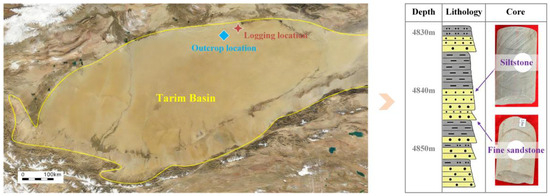
Figure 1.
Research area in the Tarim Basin.
To meet the experimental requirements for hydraulic fracturing with multi-layered sandstone samples, outcrop samples of fine sandstone and siltstone were collected from the Tarim Basin (Figure 2). Surface-weathered materials were removed to obtain intact rock masses, from which cylindrical cores were extracted by drilling. Using wire-cutting techniques, these cores were further processed into cylindrical thin slabs with a diameter of 150 mm and a height of 50 mm. The samples were constructed as three-layer composite structures arranged in either a “fine sandstone–siltstone–fine sandstone” or a “siltstone–fine sandstone–siltstone” configuration. In each assembly, the middle layer served as the targeted fracturing layer (Layer B), while the upper and lower layers acted as interlayers (Layer A and Layer C). To simulate the lithological interfaces (lithological transition zones) between layers and to secure the three-layer slabs, cement grout was used to bond the interlayered interfaces. After curing for 30 days, cubic samples with a side length of 200 mm were obtained. A central borehole with a diameter of 16 mm and a depth of 120 mm was then drilled axially into the targeted layer. This borehole consisted of an 80 mm-long wellbore section in the upper part and a 40 mm-long open hole section in the lower part. A pre-installed stainless steel casing was inserted to simulate a horizontal wellbore, and the annulus was sealed with high-strength epoxy adhesive to replicate the sealing effect of a cement sheath. This configuration ensured both the structural integrity of the wellbore and the continuity of the fluid injection pathway during fracturing, thereby completing the preparation of the multilayered sandstone samples.
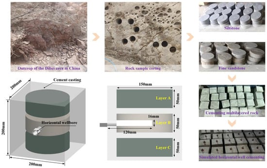
Figure 2.
Multilayered sample preparation process and geometric schematic.
2.2. Rock Mechanics Testing
As shown in Figure 3, this study conducted 8 sets of uniaxial compression tests and 7 sets of Brazilian splitting tests on both natural outcrop rocks and simulated lithological transition zones prepared with cement-based materials. The experimental results indicate that the compressive strengths of fine sandstone, siltstone, and the simulated transition zone are 92 MPa, 64 MPa, and 74 MPa, respectively. Correspondingly, their tensile strengths are 3.21 MPa, 2.35 MPa, and 2.77 MPa. These data demonstrate that fine sandstone exhibits higher rock strength than siltstone, while the transition zone presents intermediate mechanical properties. This supports the feasibility of employing cementitious materials to simulate the strength behavior of lithological transitions.
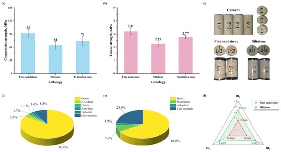
Figure 3.
Rock mechanics testing and mineralogical composition identification: (a) compressive strength; (b) tensile strength; (c) test samples; (d) fine sandstone mineral composition; (e) siltstone mineral composition; (f) brittleness index.
Furthermore, X-ray diffraction (XRD) was performed on the outcrop samples to analyze their mineral composition. The results reveal quartz contents of 83.6% in fine sandstone and 66.6% in siltstone, which further corroborates the higher hardness and strength of fine sandstone relative to siltstone. Based on the obtained mechanical and mineralogical data, the brittleness of the two rock types was evaluated using the following brittleness index (BI) formula [15]:
The BI value ranges from 0 to 1. It positively correlates with rock brittleness. Higher values indicate stronger rock brittleness. Test results show that the BI of fine sandstone ranges from 0.836 to 0.869, whereas that of siltstone is 0.666. These values indicate that fine sandstone exhibits greater brittleness than siltstone.
2.3. Experimental Procedure
Hydraulic fracturing experiments were performed using a triaxial fracturing test system (Figure 4). The experimental setup comprises five principal components: a data acquisition and control system, a confining pressure loading device, a fracturing fluid injection chamber, a triaxial loading unit, and a fluid-driven system. The data acquisition and control system operates at a maximum sampling frequency of 50 Hz. The confining pressure loading device can apply a maximum pressure of 50 MPa with an accuracy of ±0.1 MPa. The fracturing fluid injection chamber incorporates a 1500 mL storage tank and an integrated stirring mechanism. The triaxial loading unit accommodates cubic rock specimens with side lengths ranging from 100 to 400 mm by interchangeable base plates of corresponding dimensions. The fluid-driven system supports both constant-pressure and constant-flow injection modes, achieving a maximum injection rate of 60 mL/min.
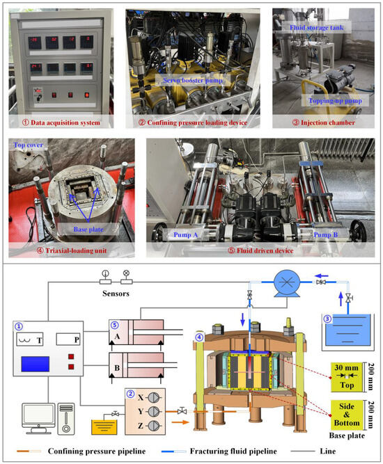
Figure 4.
True triaxial hydraulic fracturing system [16].
The experimental procedure was executed as follows. Initially, the prepared multilayered sandstone sample was securely positioned within the triaxial loading unit, and the injection pipeline was connected to the simulated wellbore to ensure a reliable fluid pathway. Subsequently, a predetermined confining pressure was applied and maintained using a servo-controlled booster pump. To accurately replicate in situ reservoir conditions, this confining pressure was sustained for a minimum duration of 30 min, allowing the rock matrix to achieve a state of mechanical equilibrium. Following the stabilization period, the injection chamber was filled with a viscous fracturing fluid containing a chemical tracer. Upon finalizing the injection parameters (e.g., rate, viscosity), the computerized data acquisition system was activated to monitor the experiment in real-time. Throughout the fluid injection phase, downhole pressure transients were recorded continuously at a sampling frequency of 10 Hz. The injection process was automatically terminated upon meeting a predefined pressure plateau criterion, indicating fracture initiation and propagation. Post-experiment, a systematic sequence of shutdown procedures was implemented, including controlled pressure relief, careful disassembly of fluid components, and the gradual release of triaxial stresses. Finally, the fractured rock sample was split open to facilitate a detailed examination and the subsequent reconstruction of the hydraulic fracture’s three-dimensional geometry.
The selection of experimental parameters was based on the actual geological conditions and engineering practices in the Tarim Basin. The vertical stress difference coefficients (KV = 0.5, 0.75, 1.5) represent low, medium, and high stress contrast conditions, respectively, covering the typical stress distribution range in this region. The injection rates of 10~50 mL/min simulate low, medium, and high pump rate scenarios used in the field. The viscosities of 3~50 mPa·s encompass the range from slickwater to linear gel, which are commonly used fracturing fluid types. These parameter ranges ensure the practical applicability of the experimental results. In this study, a total of 11 sets of hydraulic fracturing experiments were performed to investigate the propagation behavior of hydraulic fractures in the multilayered sandstone reservoir. Among these, samples S-CT #1~2 were subjected to post-fracturing CT scanning to obtain 3D reconstructions of the fracture geometry, enabling precise characterization of the fracture propagation characteristic. The remaining 9 sets of experimental samples were split, and the locations of fracturing-fluid infiltration were marked. Their 3D fracture geometries were reconstructed using SolidWorks 2025 software. The experimental design comprised the following groups: sample S-B #1 served as a baseline control for comparative analysis with other test groups; samples S-L #1~2 were used to examine the effect of interlayered lithology; samples S-S #1~2 were designed to evaluate the effect of vertical stress difference; samples S-I #1~2 were employed to analyze the impact of fracturing fluid injection rate; and samples S-V #1~2 were utilized to investigate the role of fracturing-fluid viscosity. The detailed experimental plan is summarized in Table 1.

Table 1.
Hydraulic fracturing experimental scheme.
3. Results and Analysis
3.1. Fracture Propagation Morphology
To visualize the propagation modes of hydraulic fractures in the multilayered sandstone models, samples S-CT #1 and S-CT #2 were selected for CT scanning. Based on the 2D grayscale images of the induced fractures obtained from scanning, the contrast was enhanced to improve the recognizability of the hydraulic fractures, thereby yielding fracture distribution maps at different cross-sectional positions of the rock samples, as shown in Figure 5. In sample S-CT #1, four sets of slices on the xy-planes and yz-planes, which are perpendicular to the direction of layered superposition, show horizontal fractures cutting through the middle fine sandstone layer. Conversely, the xz-plane is parallel to the layered direction and reveals predominantly vertical fracture propagation. The hydraulic fracture extension is constrained by the lithological transition zone, with no evident cross-layer behavior. Building on these observations, sample S-CT #2 was tested under modified conditions, including an increased vertical stress difference coefficient, higher fracturing fluid injection rate, and elevated fluid viscosity. The slices on the xy- and xz-planes (perpendicular to the layered superposition direction) demonstrate that the hydraulic fractures achieved vertical cross-layer propagation. Furthermore, the yz-plane (parallel to the layered superposition direction) confirms that local vertical fractures extended into the adjacent siltstone interlayers, providing a complete characterization of the 3D fracture geometry.
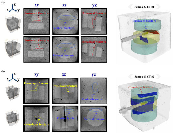
Figure 5.
The CT scanning and restructuring of the hydraulic fracture geometry in multilayered samples: (a) sample S-CT #1, passivated fracture; (b) sample S-CT #2, cross-layer fracture.
By stacking extracted 2D scan slices, the 3D fracture morphology is reconstructed, enabling clearer visualization of the initiation and propagation of hydraulic fractures in the multilayered rock sample. In the reconstructions, red represents fractures oriented horizontally, whereas blue indicates vertically oriented fractures. In the sample S-CT #1, both vertical and horizontal hydraulic fractures initiate from the open hole of the horizontal wellbore. The vertical hydraulic fracture exhibits limited height growth, terminating at the lower lithological transition zone, ultimately forming a passivated hydraulic fracture. After increasing the vertical stress contrast and adjusting the fracturing fluid parameters, the sample S-CT #2 shows a vertical fracture initiating from the open hole within the middle layer. This hydraulic fracture penetrates across the adjacent lithological transition zone and activates the interlayers on both sides, resulting in a bi-wing-shaped cross-layer fracture that achieves maximum height extension. This process enables the simultaneous vertical mobilization of multiple pay zones. Based on the CT scanning results, quantitative data on fracture dimensions were extracted. As summarized in Table 2, the fracture height in sample S-CT #1 was limited to 46.8 mm within the target layer, whereas sample S-CT #2 achieved a fracture height of 158.7 mm, activating three lithological layers. Analyzing the trends of fracture height versus the vertical stress difference coefficient, injection rate, and viscosity indicates a positive correlation between these parameters and the fracture propagation capability.
Table 2.
Quantitative analysis of fracture dimensions from CT scanning.
3.2. Fracture Behavior in Different Lithological Interlayers
To examine the effects of interlayer lithology on hydraulic fracture cross-layer propagation, 4 sets of hydraulic fracturing experiments were performed (Figure 6). Samples S-I #1 and S-B #1 were configured with fine sandstone as the targeted fracturing layer and siltstone as the adjacent interlayer. In contrast, samples S-L #1 and S-L #2 were designed with siltstone as the targeted fracturing layer and fine sandstone as the adjacent interlayer. In sample S-I #1, the hydraulic fracture initiated from the open hole of the horizontal wellbore in the fine sandstone layer, propagated vertically upward, and then deflected laterally upon reaching the upper lithological transition zone, ultimately forming a T-shaped passivated fracture. In sample S-B #1, the hydraulic fracture initiated in the siltstone layer and propagated upward. It first penetrated across the upper lithological transition zone, then activated the upper fine sandstone layer, forming a step-shaped cross-layer fracture.
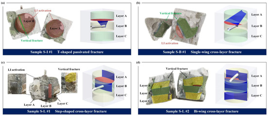
Figure 6.
Hydraulic fracture geometries of multilayered samples under different lithological interlayers: (a) sample S-I #1, siltstone interlayers; (b) sample S-B #1, siltstone interlayers; (c) sample S-L #1, fine sandstone interlayers; (d) sample S-L #2, fine sandstone interlayers.
For sample S-L #1, the hydraulic fracture initiated in the fine sandstone layer directly penetrated the lithological transition zone into the upper siltstone layer, forming a single-wing cross-layer fracture. In sample S-L #2, the hydraulic fracture initiated in siltstone layer B propagated simultaneously upward and downward, activating the adjacent fine sandstone layers, and producing a bi-wing cross-layer fracture. The experimental results indicate that hydraulic fracture vertical extension is limited, promoting lateral shear activation within the lithological transition zone when it propagates from a high-brittleness layer (fine sandstone) into a low-brittleness layer (siltstone). Conversely, when propagating from a low-brittleness layer to a high-brittleness layer, cross-layer extension is more readily achieved, while shear slip along the lithological transition zone is suppressed. It is recommended that cross-layer fracturing be prioritized in high-brittleness formations to enhance vertical reservoir stimulation and improve production performance in practical fracturing design.
3.3. Effects of Vertical Stresses on Fracture Networks
Vertical stress contrast is the key geological factor controlling the cross-layer propagation ability of hydraulic fractures in the multilayered reservoir. In this study, hydraulic fracturing experiments were conducted for 3 different vertical stress contrast coefficients (i.e., KV = 0.5, 0.75, and 1.5), and the results are shown in Figure 7. When KV = 0.5, hydraulic fractures initiated from the open hole of the horizontal well in Layer B, laterally activating the upper lithologic transition zone without crossing into adjacent interlayers, eventually forming a T-shaped passivated fracture. As KV increased to 0.75, the vertical propagation range of hydraulic fractures expanded, resulting in a single-wing cross-layer fracture, while the activation range of the lithologic transition zone significantly decreased. When KV was further raised to 1.5, hydraulic fractures initiated from Layer B and propagated vertically across interlayers, forming a bi-wing cross-layer fracture. Under this condition, the lithologic transition zone was not stimulated, but the interlayers on both sides were activated. As KV gradually increased from 0.5 to 1.5, the vertical propagation range of hydraulic fractures significantly enlarged, the number of activated layers increased from 1 to 3, and shear slip in the lithologic transition zone was effectively suppressed. It is recommended to prioritize formations with significant vertical stress contrast when implementing hydraulic fracturing operations to facilitate more extensive cross-layer propagation of hydraulic fractures, thereby enhancing the vertical stimulation effectiveness of the multilayered reservoir.
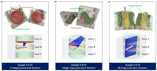
Figure 7.
Hydraulic fracture geometries of multilayered samples under different vertical stress differential coefficient: (a) sample S-S #1, KV = 0.5; (b) sample S-B #1, KV = 0.75; (c) sample S-S #2, KV = 1.5.
3.4. Fracture Propagation Under Different Injection Parameters
Fracturing fluid parameters serve as key factors governing the cross-layer propagation ability of hydraulic fractures in multilayered formations. This study investigates the influence of fracturing fluid viscosity and injection rate on hydraulic fracture propagation. As shown in Figure 8, laboratory experiments simulated hydraulic fracturing under three injection rate conditions: 10 mL/min, 35 mL/min, and 50 mL/min. At an injection rate of 10 mL/min, vertical propagation of hydraulic fractures was considerably constrained, inducing shear slip within the upper lithological transition zone and generating a T-shaped passivated fracture. When the injection rate was increased to 35 mL/min, the vertical fracture propagation range expanded substantially, enabling the hydraulic fracture to penetrate across the lithological transition zone and further activate the upper interlayer, ultimately forming a single-wing cross-layer fracture. Upon further increasing the injection rate to 50 mL/min, the vertical propagation of hydraulic fracture extent continued to enlarge, while shear slip in the lithological transition zone was markedly suppressed. Under this condition, hydraulic fractures achieved cross-layer propagation, resulting in a single-wing cross-layer fracture geometry. Overall, as the injection rate rose from 10 mL/min to 50 mL/min, the number of activated lithological layers approximately doubled, significantly improving the vertical stimulation effectiveness of the reservoir.
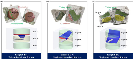
Figure 8.
Hydraulic fracture geometries of multilayered samples under different injection rates of fracturing fluid: (a) sample S-I #1, Q = 10 mL/min; (b) sample S-B #1, Q = 35 mL/min; (c) sample S-I #2, Q = 50 mL/min.
As shown in Figure 9, three hydraulic fracturing experiments were performed using fracturing fluids with viscosities of 3 mPa·s, 10 mPa·s, and 50 mPa·s. At a viscosity of 3 mPa·s, hydraulic fractures propagated in a T-shaped passivated pattern, which did not effectively connect the adjacent interlayers. When the viscosity was increased to 10 mPa·s, the hydraulic fractures transitioned to vertical propagation, successfully activating the upper interlayer and forming a single-wing cross-layer fracture. Further increasing the viscosity to 50 mPa·s significantly extended the vertical propagation range of the hydraulic fractures, strongly suppressing shear slippage in lithological transition zones, and ultimately generating a bi-wing cross-layer fracture. As fracturing fluid viscosity rose from 3 mPa·s to 50 mPa·s, the number of activated layers increased from 1 to 3, substantially improving the vertical stimulation coverage of the reservoir. To achieve multi-layer co-production and effectively expand the lateral stimulation range, it is recommended to employ hydraulic fracturing techniques that utilize cyclic injection with alternating sequences of high and low viscosity or high and low injection rate.
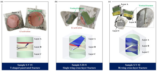
Figure 9.
Hydraulic fracture geometries of multilayered samples under different viscosities of fracturing fluid: (a) sample S-V #1, μ = 3 mPa·s; (b) sample S-B #1, μ = 10 mPa·s; (c) sample S-V #2, μ = 50 mPa·s.
4. Conclusions
In this paper, experiments on hydraulic fracturing in multilayered sandstone with lithological transition zones were conducted. The propagation behavior of hydraulic fractures in multilayered sandstone was investigated. The effects of interlayer lithology, vertical stress difference, fracturing fluid injection rate, and viscosity on the vertical propagation of hydraulic fractures were analyzed. The main conclusions are as follows:
(1) In multilayered sandstone reservoirs, hydraulic fracturing forms passivated and cross-layer type fracture networks while inducing laterally activated propagation within lithological transition zones.
(2) When hydraulic fractures propagate from high-brittleness into low-brittleness layers, the vertical extension range is limited, thereby promoting lateral shear activation along lithological transition zones.
(3) With increasing vertical stress contrast, the hydraulic fractures exhibit an expanded vertical propagation range. The hydraulic fracture morphology transitions from a passivated type to a single-wing cross-layer type and ultimately to a bi-wing cross-layer type.
(4) Increasing the injection rate and viscosity of fracturing fluid facilitates the propagation of hydraulic fractures across adjacent interlayers while suppressing the activation of lithological transition zones.
Author Contributions
R.L.: Writing—original draft, Investigation, Conceptualization. T.L.: Methodology & Investigation. X.W.: Methodology & Funding acquisition. S.W.: Writing—review & editing. Z.H.: Methodology & Funding acquisition. R.Y.: Writing—review & editing. Q.X.: Investigation. N.H.: Investigation. All authors have read and agreed to the published version of the manuscript.
Funding
This work was supported by the National Natural Science Foundation of China (No. 52421002, No. 52474016).
Data Availability Statement
The data presented in this study are available on request from the corresponding author.
Conflicts of Interest
Authors Rui Liang and Subing Wang are employed by CNPC Chuanqing Drilling Engineering Company Limited. Author Qiang Xu is employed by PetroChina Tarim Oilfield Company. Author Naikun Hu is employed by Tianjin Geothermal Exploration and Development-Designing Institute. The remaining authors declare that the research was conducted in the absence of any commercial or financial relationships that could be construed as a potential conflict of interest.
References
- Wang, H.; Ma, F.; Tong, X.; Liu, Z.; Zhang, X.; Wu, Z.; Li, D.; Wang, B.; Xie, Y.; Yang, L. Assessment of global unconventional oil and gas resources. Pet. Explor. Dev. 2016, 43, 925–940. [Google Scholar] [CrossRef]
- Lu, H.; Lu, X.; Fan, J.; Zhao, M.; Wei, H.; Zhang, B.; Lu, Y. Controlling effect of fractures on gas accumulation and production within the tight sandstone: A case study on the Jurassic Dibei gas reservoir in the eastern part of the Kuqa foreland basin, China. J. Nat. Gas Geosci. 2016, 1, 61–71. [Google Scholar] [CrossRef]
- Guo, J.; Gou, B.; Qin, N.; Zhao, J.; Wu, L.; Wang, K.; Ren, J. An innovative concept on deep carbonate reservoir stimulation: Three-dimensional acid fracturing technology. Nat. Gas Ind. B 2020, 7, 484–497. [Google Scholar] [CrossRef]
- Wei, G.; Wang, K.; Zhang, R.; Wang, B.; Yu, C. Structural diagenesis and high-quality reservoir prediction of tight sandstones: A case study of the Jurassic Ahe Formation of the Dibei gas reservoir, Kuqa depression, Tarim basin, NW China. J. Asian Earth Sci. 2022, 239, 105399. [Google Scholar] [CrossRef]
- Hou, B.; Zhang, Q.; Lv, J. Distributed Fiber Optic Monitoring of Asymmetric Fracture Swarm Propagation in Laminated Continental Shale Oil Reservoirs. Rock Mech. Rock Eng. 2024, 57, 5067–5087. [Google Scholar] [CrossRef]
- Xie, Z.; Long, T.; Wu, X.; Huang, Z.; Li, G.; Song, X.; Yang, R.; Pan, T.; Zou, W.; Sun, Z.; et al. Radial borehole fracturing in the multilayered shale oil reservoir based on a 3D discrete lattice model. Eng. Geol. 2025, 359, 108444. [Google Scholar] [CrossRef]
- Zhang, J.; Yu, Q.; Li, Y.; Pan, Z.; Liu, B. Hydraulic Fracture Vertical Propagation Mechanism in Interlayered Brittle Shale Formations: An Experimental Investigation. Rock Mech. Rock Eng. 2023, 56, 199–220. [Google Scholar] [CrossRef]
- Cao, M.; Sharma, M.M. An Inversion-Based Microseismic Simulator for Fracture Diagnostics. Rock Mech. Rock Eng. 2024, 1–17. [Google Scholar] [CrossRef]
- Cao, M.; Sharma, M.M. Factors Controlling the Flow and Connectivity in Fracture Networks in Naturally Fractured Geothermal Formations. SPE Drill. Complet. 2023, 38, 131–145. [Google Scholar] [CrossRef]
- Cao, M.; Sharma, M.M. Impact of Dynamic Changes in Natural Fracture Fluid Pressure on the Propagation and Geometry of Hydraulic Fracture Networks. SPE J. 2025, 30, 2404–2417. [Google Scholar] [CrossRef]
- Cao, M.; Sharma, M.M. The impact of changes in natural fracture fluid pressure on the creation of fracture networks. J. Pet. Sci. Eng. 2022, 216, 110783. [Google Scholar] [CrossRef]
- Cawood, A.J.; Bond, C.E. 3D mechanical stratigraphy of a deformed multi-layer: Linking sedimentary architecture and strain partitioning. J. Struct. Geol. 2018, 106, 54–69. [Google Scholar] [CrossRef]
- Jeng, F.S.; Weng, M.C.; Lin, M.L.; Huang, T.H. Influence of petrographic parameters on geotechnical properties of tertiary sandstones from Taiwan. Eng. Geol. 2004, 73, 71–91. [Google Scholar] [CrossRef]
- Shi, H.; Luo, X.R.; Lei, G.L.; Zhang, L.Q.; Zhang, L.K.; Lei, Y.H. Diagenesis and Fluid Flow Variability of Structural Heterogeneity Units in Tight Sandstone Carrier Beds of Dibei, Eastern Kuqa Depression. Geofluids 2017, 2017(1), 6593913. [Google Scholar] [CrossRef]
- Zhang, D.; Ranjith, P.G.; Perera, M.S.A. The brittleness indices used in rock mechanics and their application in shale hydraulic fracturing: A review. J. Pet. Sci. Eng. 2016, 143, 158–170. [Google Scholar] [CrossRef]
- Long, T.; Yang, R.; Pan, T.; Huang, Z.; Wu, X.; Li, G.; Xie, Z.; Zou, W.; Sun, Z.; Sun, Y.; et al. Hydraulic fracture cross-layer propagation characteristics in the interlayered sand-shale reservoir. Phys. Fluids 2025, 37, 096616. [Google Scholar] [CrossRef]


Disclaimer/Publisher’s Note: The statements, opinions and data contained in all publications are solely those of the individual author(s) and contributor(s) and not of MDPI and/or the editor(s). MDPI and/or the editor(s) disclaim responsibility for any injury to people or property resulting from any ideas, methods, instructions or products referred to in the content. |
© 2026 by the authors. Licensee MDPI, Basel, Switzerland. This article is an open access article distributed under the terms and conditions of the Creative Commons Attribution (CC BY) license.