Abstract
The relevance of this study is determined by the need for new technological solutions to enhance the productivity of wells producing heavy and highly viscous crude oil. The work investigates multicomponent Al–Ga–In–Sn alloys as reactive systems capable of generating heat and hydrogen upon contact with water. The focus is placed on optimizing melting parameters and assessing how alloy composition and structural features affect reactivity. Phase composition was analyzed by X-ray diffraction, microstructure by SEM-EDX, and elemental composition by XRF. The results show that the hydrogen generation rate and heat release depend on melting temperature, holding time, and ratios of activating metals, as well as the physicochemical properties of the formation water, particularly salinity and pH. Reaction enthalpy and conversion efficiency were quantified. The highest hydrogen output and thermal effect were observed for the following compositions—90 wt.% Al, 5 wt.% Ga, 2.5 wt.% In, 2.5 wt.% Sn; and 85 wt.% Al, 5 wt.% Ga, 5 wt.% In, 5 wt.% Sn (825 °C, 30 min). Rapid heat and gas release is attributed to the eutectic structure and micro-galvanic interaction, which eliminate the induction period. These findings demonstrate the potential of such alloys for in situ heating, enhanced oil recovery, and autonomous hydrogen-energy applications.
1. Introduction
A promising direction for maintaining economically viable production levels in oil fields is the development of new reservoirs and the enhancement of production efficiency in long-term exploited heavy oil fields (HO). Despite the significance and urgency of the issue, many aspects related to improving well productivity in heavy oil reservoirs remain unresolved [1,2,3,4,5]. In operating oil fields, an increasing proportion of wells are complicated by high-viscosity production and intense formation of asphalt–resin–paraffin deposits (ARPD), associated with the elevated content of asphaltenes, resins, and paraffinic hydrocarbons in crude oil. The formation of complex ARPD occurs both within the near-wellbore zone (NWZ) and on downhole equipment and tubing, resulting in a substantial decline in reservoir filtration properties, reduced inflow to producing wells, and hindered transportation of crude oil through field pipelines [3,4,5].
Field practices have demonstrated the effectiveness of several enhanced oil recovery (EOR) and stimulation technologies, including cyclic steam stimulation (CSS), steam-assisted gravity drainage (SAGD), cold heavy oil production with sand (CHOPS), vapor extraction using solvents (VAPEX), solvent-assisted processes (SAP), a combination of in situ combustion and horizontal well production (THAI), and the catalyst-assisted process (CAPRI), which represents an extension of THAI with catalytic upgrading mechanisms [4,5,6].
At the same time, the application of the aforementioned technologies is characterized by high energy consumption, technological complexity, and limited effectiveness in the presence of persistent asphaltene–resin–paraffin deposits (ARPD) and low-permeability reservoirs, which necessitates the search for alternative or complementary stimulation methods.
Modern approaches to combined hydrogen and thermobarochemical stimulation (CHTBS) of the near-wellbore formation are actively evolving [7,8]. These technologies integrate the key mechanisms of both physical and chemical treatment methods to enhance reservoir permeability and productivity [9].
Since the 1970s, a large number of studies have been devoted to the development of hydro-reactive materials, as they gave rise to a new research direction known as “hydrogen energy.” The prospects of this field are reflected in numerous studies focused on the synthesis of substances that actively interact with water to produce hydrogen—an environmentally friendly fuel [10,11,12,13,14,15,16,17,18]. Activation of aluminum by metallic activators (In, Ga, Sn, Mg, Cd, Zn, Pb, Bi), as well as by low-temperature liquid metal alloys based on gallium, enables the oxidation of aluminum by water under ambient conditions with hydrogen generation [12,13,14,15,16,17,18,19,20,21,22,23]. Activated aluminum alloys are therefore considered promising sources for clean hydrogen production, while the simplicity of hydrogen storage and transportation using such materials has also been emphasized [10,11,12].
Research in the field of hydrogen production has been developing intensively in recent years [16,17,18,19,20,21,22,23]. In studies of the reaction mechanism in the Al–water system, experimental methods such as gas evolution measurements and calorimetry are predominantly employed. Differential scanning calorimetry (DSC) is used to determine the onset temperature of the exothermic Al–water reaction, while changes in particle size and morphological transformations of reaction products during the Al–water interaction have also been identified [14,17]. A clear relationship between the hydrogen generation rate and the microstructure of aluminum alloys has been established. It has been demonstrated [19,24] that activation of aluminum with In, Ga, and Sn is accompanied by the formation of intermetallic compounds (Al–Ga, Al–In) [24], penetration of a liquid phase along aluminum grain boundaries with the effect of liquid metal embrittlement, disruption of the crystal lattice, and an increase in the active surface area. These elements inhibit the formation of a dense Al2O3 oxide layer, thereby sustaining continuous interaction between the metal and water. The high reactivity of such alloys toward water is attributed to mechanical loosening of the structure, enlargement of the reactive surface, crystallite dispersion, formation of microgalvanic cells, and the presence of eutectics in the immiscibility region of the liquid phase [24,25,26,27,28,29,30,31]. Owing to the small crystallite size and the presence of microgalvanic couples, aluminum oxidation proceeds with little or no induction period [24,25].
The role of indium and tin in aluminum-based alloys has been elucidated, and a new mechanism of embrittlement of the Al matrix based on low-melting phases in Al–Ga-based alloys has been proposed. This mechanism served as a guideline for interpreting material properties and for precise materials design. It was experimentally confirmed that indium promotes the formation of deeper and wider cracks within the alloy compared to tin, making the alloy more brittle during hydrolysis and resulting in higher hydrogen productivity, whereas tin primarily accelerates the reaction rate [23].
In addition, the mechanisms of catalytic hydrolysis of borohydrides and activation of aluminum-based materials through Mg/Al alloying, as well as hydrogen generation at subzero temperatures for potential off-board or on-board vehicle applications, have been studied in detail [16,17]. During sodium borohydride regeneration, the associated costs are significantly reduced, making hydrolysis/alcoholysis more practical for use in on-site hydrogen generation systems or fuel cells. This is attributed to advantages such as low operating temperature, environmentally benign by-products, precise control of hydrogen release, and the production of high-purity H2.
In this study, the authors for the first time propose the use of aluminum-based alloys as an alternative energy source for integrated crude oil treatment, including the destruction of abnormally stable water–oil emulsions, thermogasochemical stimulation of the near-wellbore zone of high-viscosity oil wells, removal of asphaltene–resin–paraffin deposits (ARPD) in long-term operated fields, and enhancement of reservoir productivity [32,33,34]. In the presence of atomic and molecular hydrogen and catalysts, hydrocracking of ARPD occurs with the formation of gaseous and distillate fractions. As a result, oil recovery efficiency reaches up to 95%, the content of light hydrocarbons increases to 26%, and oil viscosity decreases by approximately 35% [25]. A significant reduction in the content of natural emulsion stabilizers—asphaltenes and aliphatic paraffins—by 0.5–3.5% was observed. In addition, a substantial decrease in sulfur content in heavy hydrocarbon feedstocks was achieved: by 82% in Karazhanbas crude oil, by 98% in oil sludges, by 64% in fuel oil, and by 51% in vacuum residue (gudron). Furthermore, a twofold reduction in the mineralization of the separated water was recorded [32,33].
The innovative technology being developed for restoring well productivity using aluminum-based alloys combines conventional physical and chemical methods of near-wellbore zone treatment [34].
However, the relationships governing the influence of composition and melting regimes of four-component Al–Ga–In–Sn alloys on their reactivity, heat release, and hydrogen generation under the high-temperature and high-pressure conditions characteristic of high-viscosity oil (HVO) near-wellbore zone treatment remain insufficiently studied.
The aim of this study is to investigate the effect of melting regimes and composition of four-component alloys based on light and dispersed metals (Al–Ga–In–Sn) on their structure, mechanical properties, heat release, and hydrogen generation, as well as to evaluate the reactivity of these alloys during interaction with formation water through measurements of heat evolution and gaseous reaction products (hydrogen).
2. Materials and Methods
2.1. Materials Used
Aluminum granules were supplied by JSC Aluminium of Kazakhstan, Pavlodar. The material specifications were as follows: melting point—660.0 °C, density—2.70 g/cm3, and purity—99.85%.
Gallium (Ga) in the form of cylindrical ingots weighing 900–1000 g was obtained from JSC Aluminium of Kazakhstan, Pavlodar. The metal had a melting point of 29.80 °C, density—5.904 g/cm3 at 20 °C, and purity—99.99%.
Indium (In) in the form of cylindrical ingots weighing 0.05 g to 1000 g was supplied by JSC Aluminium of Kazakhstan, Pavlodar. The material properties were: melting point—156.59 °C, density—7.362 g/cm3 at 20 °C, and purity—99.999%.
Tin (Sn) was supplied in ingots weighing 22–26 kg from Granhim LLC, Chelyabinsk, Russia. The tin content was 99.565%, and the melting point was 231.91 °C.
Hydrochloric acid (HCl, chemically pure grade) with an azeotropic boiling point of 108.6 °C (20.22 wt.% HCl) and density of 1.16 g/cm3 (35%) was used without additional purification from Kaustik JSC Pavlodar, Kazakhstan.
The selection of alloys for the experimental studies was determined by the possibility of regulating their reactivity through variations in the content of alloying additives, as well as by the need for their detailed investigation with regard to practical application and implementation under field conditions. Aluminum activation was based on the Rebinder effect, which involves the use of activating metals to induce embrittlement of a solid due to a reduction in surface energy and adsorption-induced weakening. Under these conditions, surface fracture becomes thermodynamically favorable [35].
2.2. Fabrication of Multicomponent Aluminum Alloys
Al–Ga–In–Sn alloys were produced using a conventional melting and casting technique in a graphite crucible in an SNOL 7.2/1100 furnace made in Lithuania. The process involved melting aluminum, sequential addition of activating metals, holding of the melt, casting into a graphite mold, and subsequent cooling in a vacuum chamber. To establish the main oxidation regimes and to determine the parameters of heat and gas evolution as functions of melting temperature and alloy composition, a series of alloy samples was prepared.
The melting temperature was varied in the range of 750–900 °C, and the holding time ranged from 30 to 90 min. High-purity metals (>99%) were used for alloy preparation. Table 1 summarizes the melting temperature regimes applied for the fabrication of multicomponent Al–Ga–In–Sn alloys containing activating metals in the following mass fractions: indium 1–7 wt%, gallium 1–14 wt%, tin 1–7 wt%, with aluminum constituting the balance.

Table 1.
Melting conditions and compositions of multicomponent alloys of light and dispersed metals.
For experimental studies, the obtained alloy ingots were crushed into powder with particle sizes up to 0.6 mm by triple-stage grinding using an MF 10 Basic analytical Staufen, Germany mill. Prior to fine grinding, the ingots were pre-crushed to a size of 5–10 mm. The duration of each grinding cycle was 60 s. After the third grinding cycle, the powder was sieved through a 600 μm mesh to remove oversized particles, ensuring particle size uniformity and experimental reproducibility. The resulting powders with a particle size distribution of 600–1250 μm were stored in sealed containers under an inert atmosphere to prevent oxidation.
In addition, the alloys were crushed in a pure argon atmosphere using a fine jaw crusher (DMD 160 × 100 mm), operated under a programmed crushing regime designed to obtain the required granulometric composition while maintaining an inert environment. Specifically, after four successive crushing stages of the aluminum alloy with stepwise adjustment of the jaw gap (1, 2, 5, and 0 mm), the following particle size distribution was obtained: 2.5 mm–3.7%; 1.25 mm–46.1%; 0.63 mm–31.26%; 0.35 mm–17.96%; 0.14 mm–0.10%; <0.140 mm–0.84%.
2.3. Study of the Alloys
The elemental composition of the obtained alloys was determined by X-ray fluorescence (XRF) analysis using an Innov-X Systems X-Ray spectrometer Woburn, MA, USA. Sample preparation included mechanical grinding of the surface with sandpaper of grit sizes 400–1200, degreasing with acetone, and air drying. Measurements were performed at room temperature without the use of vacuum or a helium atmosphere. The acquisition time for a single measurement was 60–120 s. Each reported value represents the average of four independent measurements taken at different locations on the sample surface (n = 4). The precision of the method for the main components (Al, Ga, In, Sn) in the aluminum matrix was estimated to be ±0.1–0.4 wt.% based on repeatability and the manufacturer’s specifications of the instrument.
The microstructural analysis of the alloy and its reaction products was carried out using a JSM-6490LV scanning electron microscope (JEOL) Munchen, Germany equipped with an INCA Energy 350 energy-dispersive X-ray spectroscopy (EDS) system (Oxford Instruments, Abingdon, United Kingdom). In addition, an electron probe microanalyzer Superprobe-733 (JEOL) Munchen, Germany was employed at an accelerating voltage of 25 kV and a probe current of 25 nA.
Based on the microstructural analysis, phase constituents located along the aluminum grain boundaries were identified. Micrographs were acquired in secondary electron (SE) and backscattered electron (BSE) modes, as well as using characteristic X-ray emission of Ga, In, and Sn for elemental mapping of their spatial distribution. Sample preparation included mechanical grinding, polishing, and light etching to reveal the microstructure.
The study was carried out on alloy samples No. 2.1 (Al 85.7: Ga 4.5: In 4.5: Sn 5.1), No. 6.1 (Al 92.5: Ga 2.5: In 2.5: Sn 2.5), and No. 7.5 (Al 97: Ga 1: In 1: Sn 1). The BSE mode makes it possible to identify inclusions and the distribution of heavy elements (Ga, In, Sn) based on contrast, with brightness increasing as the average atomic number increases. The SE mode provides information on surface morphology, pore shape and size, as well as fracture characteristics. X-ray diffraction (XRD) analysis of the reaction products of alloy No. 2.1 formed in different oxidizing media (water and 5% HCl solution) was performed using an automated DRON-3 diffractometer with CuKα radiation (λ = 1.5406 Å) and a β-filter. The diffraction patterns were recorded under the following conditions: accelerating voltage U = 35 kV, current I = 20 mA, in the angular range 2θ = 20–90°, with a scanning rate of 2°/min. The quantitative phase composition of the crystalline phases was determined on a semi-quantitative basis from powder diffraction patterns using the equal-weight method and artificial mixtures.
2.4. Hydrogen Generation and Thermochemical Treatment
In studying the reaction in the Al–water system, methods of gas product (hydrogen) measurement and calorimetry were used. The equipment for hydrogen generation was described in a previous study [33].
The experiment for measuring the volume of released hydrogen was carried out as follows:
- −
- a glass reactor in the form of a three-neck round-bottom flask equipped with a heating jacket for maintaining a constant temperature, with a total volume of 500 mL, was charged with 250 mL of water or a 3% hydrochloric acid solution.
- −
- the aluminum alloy was introduced into the flask through one of the necks, after which the system was hermetically sealed, and the gas volume was measured using a drum-type gas meter.
- −
- one of the three necks of the flask was connected, via a reflux condenser, to the drum-type gas meter, which recorded the volume of gas released during the exothermic reaction of the alloy with water.
The evolved hydrogen was converted to the equivalent volume of H2 under standard conditions (273 K, 1 atm) using the ideal gas equation. For each comparative experiment, the mass of the alloy added to the reaction flask was 2.5 g, and each test was repeated at least three times.
To convert the measured gas volume to standard conditions, the following equation was used:
where
V = Vt ((P + B) × (273 + 20)/(101,325 × (273 + t)
- V—gas volume corrected to standard conditions (20 °C, 101,325 Pa), dm3;
- t—temperature of the measured gas, °C;
- Vt—gas volume measured by the gas meter at temperature t and pressure P, dm3;
- P—pressure of the gas entering the meter, Pa;
- B—atmospheric pressure, Pa.
The hydrogen yield was evaluated using the ratio:
where
YH2 = V/V0
- V—the measured volume of hydrogen generated during the reaction, L;
- V0—the theoretical (stoichiometric) hydrogen yield, calculated as 1.244 L per gram of Al under standard conditions (20 °C, 101,325 Pa).
It has been experimentally confirmed that atomic hydrogen activates diffusion processes, increases the gas permeability of productive reservoir formations by a factor of 2–4.5, and promotes the filtration of chemically active components [32,33].
2.5. Calculation of Alloy Density
The density of the alloys was calculated using the following equation [36]:
where
ρ = 1/(wi/ρAL + wi/ρGa+ wi/ρSn)
- wi—mass fraction of component i (expressed as a fraction of 1);
- ρAl, ρGa, ρIn, ρSn—densities of the pure elements (tabulated values, g/cm3).
Example of calculation:
- ρAl = 2.70, ρGa = 5.91, ρIn = 7.31, ρSn = 7.31.
- wAl = 0.92, wGa = 0.05, wIn = 0.02, wSn = 0.01.
- wAl/ρAl = 0.92/2.70 = 0.3407407
- wGa/ρGa = 0.05/5.91 = 0.008455
- wIn/ρIn = 0.02/7.31 = 0.002735
- wSn/ρSn = 0.01/7.31 = 0.0013675
The density of the alloy: ρ = 1/0.3532982407 ≈ 2.830 g/cm3.
The calculated density values of multicomponent alloys of light and dispersed metals produced at a melting temperature of 850 °C are presented in Table 2.
Table 2.
Calculated density values of multicomponent alloys of light and dispersed metals produced at a melting temperature of 850 °C.
With an increase in the content of activating metals from 0.5 wt.% to 5 wt.%, the density of the alloys increases compared to pure aluminum, rising from 2.725 g/cm3 to 2.968 g/cm3, respectively.
2.6. Mechanical Testing
The mechanical properties were determined by uniaxial tensile testing using cylindrical specimens with a diameter of 5 mm and a gauge length of 25 mm, machined from cast billets with dimensions of 12 × 60 mm. The alloys were prepared by melting aluminum with additions of Ga, In, and Sn (0.1–5.0 wt.% of each element) at 670 °C, followed by quenching in liquid nitrogen to preserve the non-equilibrium state. Tensile tests were carried out on a universal testing machine at room temperature with a constant crosshead speed of 1 mm/min. For each alloy composition, at least 3–5 parallel measurements were performed.
2.7. Statistical Analysis
All experimental measurements were performed in triplicate (n = 3) to ensure reproducibility and reliability of the results. Experimental data are presented as mean values with the corresponding standard deviation (mean ± SD). Differences were considered statistically significant at a significance level of p < 0.05.
3. Results
3.1. X-Ray Spectral Analysis of the Elemental Composition of Multicomponent Alloys
The quantitative elemental composition of the alloy was determined by X-ray fluorescence spectroscopy (pXRF) using an Innov-X Delta analyzer Woburn, MA, USA, with the results averaged over four measurements taken at different areas of the sample (Table 3).
Table 3.
Elemental composition of four-component Al–Ga–In–Sn alloys.
The obtained elemental composition values are in good agreement with the target compositions (the deviation does not exceed 0.7 wt.% for all elements), confirming the absence of significant component losses during melting and casting in the temperature range of 750–900 °C. The largest deviation was observed for tin in alloy 6.1 (+0.22 wt.%), which may be attributed to its higher volatility during prolonged holding at elevated temperatures. Overall, the deviations fall within the expected analytical uncertainty of the method for light and medium elements in an aluminum matrix.
3.2. X-Ray Structural Analysis of Multicomponent Aluminum Alloys
SEM images and EDX maps of the surface of alloy No. 2.1 and alloy No. 7.5 are shown in Figure 1 and Figure 2.
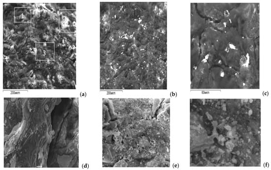
Figure 1.
SEM images of the surface of the multicomponent alloy No. 2.1: (a) secondary electron (SE) mode; (b) backscattered electron (BSE) mode; (c) magnified fragment of image (b); (d) ×1000 magnification; (e) ×5000 magnification; (f) ×2000 magnification.
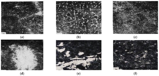
Figure 2.
SEM images of the surface of the multicomponent alloy No. 7.5: (a) ×780, characteristic X-ray map of Ga; (b) ×400, BSE mode; (c) ×300, BSE mode; (d) ×1100, characteristic X-ray map of In; (e) ×2200, characteristic X-ray map of Ga; (f) ×1100, characteristic X-ray map of Sn.
These investigations made it possible to obtain an overall characterization of the alloys, including SEM images of the fracture surface, phase distribution, and the spatial distribution of dissolved elements within the alloy, as well as their local concentrations measured by an electron microprobe with a probe diameter of 1 μm. Brighter regions in the micrographs indicate the presence of liquid eutectic phases of the activating metals on the aluminum grains. The higher the concentration of heavy elements in a given grain region, the brighter this region appears in the SEM images.
EDX maps and spectra of the bright white grains (a,b) and the matrix (c, gray phase) of alloy No. 2.1 are shown in Figure 3.
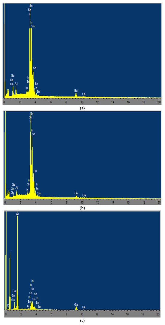
Figure 3.
EDS elemental mapping and spectra for the multicomponent alloy (Alloy No. 2.1): (a) Spectrum 1; (b) Spectrum 2; (c) Spectrum 3.
The results of EDX analysis of the bright white grains and the aluminum alloy matrix are summarized in Table 4. Based on these data, it can be concluded that the bright white grains are compositionally heterogeneous. The activating components Ga, In, and Sn participate in the formation of complex eutectic phases and exhibit non-uniform distribution both within the bulk and on the surface of the aluminum matrix.
Table 4.
Results of EDX analysis of bright white grains and the matrix of aluminum alloy No. 2.1 [20].
Based on the data presented in the table, it can be concluded that the bright white grains are compositionally heterogeneous. The activating components Ga, In, and Sn in the alloy participate in the formation of complex eutectics and exhibit different distributions within the bulk and on the surface of aluminum. The high contents of In and Sn in the bright white grains (eutectic inclusions), combined with a low aluminum content, confirm the formation of liquid/semi-liquid Ga–In–Sn phases at the aluminum grain boundaries (Figure 3). These phases are characterized by low melting temperatures (approximately 10–20 °C for the ternary Ga–In–Sn eutectic) and promote the destruction of the passive Al2O3 oxide film, facilitate the diffusion of Al atoms to the reaction surface, and enable continuous interaction of the alloy with water without an induction period. This explains the enhanced reactivity of alloys with high activator contents (e.g., No. 2.1) compared with low-alloyed compositions (e.g., No. 7.5).
The results of X-ray diffraction (XRD) analysis of the phase composition of the alloys are presented in Table 5.
Table 5.
X-ray diffraction (XRD) results of multicomponent aluminum–dispersed metal alloys (alloys No. 2.1, No. 6.1, and No. 7.5) [20].
According to the XRD data, the phase composition of the activated aluminum alloys includes intermetallic phases of various compositions. XRD analysis of alloy No. 2.1 revealed the presence of aluminum as the main matrix, a solid solution of gallium in aluminum ((Al0.95Ga0.05)), as well as various binary In–Sn intermetallic compounds, including (In3Sn)0.5, (InSn4)0.2, In0.1818Sn0.8182, In1.74Sn0.26, In0.2Sn0, and others.
The content of the Al0.95Ga0.05 phase increases sharply (up to 67%) with a decrease in the concentration of activators to 2.5 wt.% each (alloy No. 6.1), indicating more complete dissolution of Ga in the aluminum matrix at lower In and Sn contents. In contrast, at a high activator content (alloy No. 2.1), the fraction of In–Sn intermetallic phases increases, while the content of the gallium-containing solid solution decreases.
The obtained data are in good agreement with literature reports [18,19,20,24,25,26,27,28], where the formation of Ga–In–Sn eutectic phases at grain boundaries is recognized as a key mechanism for aluminum activation in reactions with water.
The high contents of In and Sn in the bright white grains (eutectic inclusions), combined with a low Al content, confirm the formation of liquid/semi-liquid Ga–In–Sn phases at the grain boundaries (Figure 3).
3.3. Investigation of the Mechanical Properties of Multicomponent Alloys of Light and Dispersed Metals
The mechanical properties of Al–Ga–In–Sn alloys were determined by uniaxial tensile testing of cylindrical specimens (Ø 5 mm, gauge length = 25 mm) at room temperature and a constant strain rate of 1 mm/min, with 3–5 parallel measurements performed for each composition. The alloys were prepared by melting aluminum with activator metals in the range of 0.1–3.0 wt.% at 670 °C, followed by rapid quenching in liquid nitrogen in order to obtain a non-equilibrium material.
Specimens with a diameter of 5 mm and a gauge length of 25 mm were machined from cast billets (12 × 60 mm) and tested on a tensile testing machine. During the experiments, the ultimate tensile strength and elongation were determined. The results of the ultimate tensile strength measurements for binary and multicomponent aluminum alloys as a function of the type and amount of introduced activator metals are presented in Figure 4 and Figure 5.
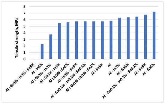
Figure 4.
Dependence of the ultimate tensile strength of binary and multicomponent aluminum alloys on the type and concentration of activating metal additives.
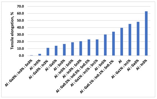
Figure 5.
Dependence of ductility (elongation at fracture) of binary and multicomponent aluminum alloys on the type and concentration of activating metal additives.
The introduction of activator metals leads to a sharp decrease in ultimate tensile strength (σt) from 5.78 MPa for pure aluminum to 0.03 MPa for the alloy Al 91–Ga 3–In 3–Sn 3%, and a corresponding reduction in elongation (δ) from 39.5% to 0.05%. Activator metals reduce the surface energy and promote the adsorption-induced reduction in strength (Rebinder effect). An increase in the content of activator metals results in refinement of the aluminum grain structure and an increase in the amount of eutectic phases formed, as well as their distribution throughout the alloy volume. The lowest values of strength and ductility are observed for aluminum alloys containing 3.0 wt.% of gallium, indium, and tin. Brittleness is also induced by small additions of Ga, In, and Sn, which tend to concentrate at grain boundaries due to their rapid diffusion.
The obtained data confirm [18,21] that the activation of aluminum is inevitably accompanied by a loss of mechanical strength and ductility.
3.4. Measurement of the Reactivity of Al Alloys in Water and Aqueous HCl Solutions
The reactivity of Al–Ga–In–Sn alloys was evaluated based on the volume and rate of hydrogen evolution during their interaction with distilled water and aqueous hydrochloric acid solutions (1–5 wt.%) at 25 °C. The reaction is accompanied by intense gas evolution and heat release. The experiments were carried out in a sealed 500 mL three-neck glass reactor using a drum gas meter to record the volume of gas, recalculated to standard conditions (273 K, 101.325 kPa).
The mass of the alloy charge was varied from 1.0 to 5.0 g, and the alloy:HCl/water ratio ranged from 1:25 to 1:100. Each experiment was repeated at least three times; the standard deviation did not exceed p ≤ 0.05. The theoretical hydrogen yield is 1.244 L H2 per 1 g of Al at 100% conversion.
The diagram of the steam–hydrogen mixture yield during oxidation with a 3% HCl solution of multicomponent alloys produced at a melting temperature of 800 °C for 30 min (alloy No. 1.1), 60 min (alloy No. 1.2), and 90 min (alloy No. 1.3) is shown in Figure 6. The studies were conducted at an alloy-to-acid solution ratio of 1:100 (5 g of alloy, 500 mL of acid solution).
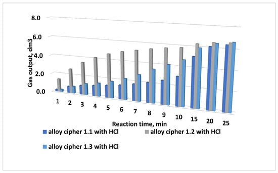
Figure 6.
Yield of the steam–hydrogen mixture during oxidation with a 3% HCl solution of multicomponent alloys with the composition Al 85:Ga 5:In 5:Sn 5, produced at 800 °C for 30 min (alloy No. 1.1), 60 min (alloy No. 1.2), and 90 min (alloy No. 1.3).
Analysis of the diagrams indicates that the oxidation rate can be controlled by varying the melting temperature, the alloy composition, and the amount of activating metals introduced into the alloy. Alloys produced at a melting temperature of 800 °C and held in a muffle furnace for 60 and 90 min yield a higher amount of the steam–hydrogen mixture during oxidation than alloys held for only 30 min.
However, short-term peak (“impulse”) gas release rates are higher for the alloy produced at a melting temperature of 825 °C. The best hydrogen generation performance was demonstrated by alloy No. 2.1 with the composition Al:Ga:In:Sn = 85:5:5:5.
Such impulse gas releases are expected to be most effective for the removal of asphalt–resin–paraffin deposits (ARPD) and capable of disrupting clogging formations in the well.
The yield of the steam–hydrogen mixture during oxidation of alloy No. 2.1 with a 3% hydrochloric acid solution as a function of the melting temperature is shown in Figure 7. The results indicate that the maximum yield is achieved for the alloy produced at a melting temperature of 825 °C with a melt holding time of 30 min.
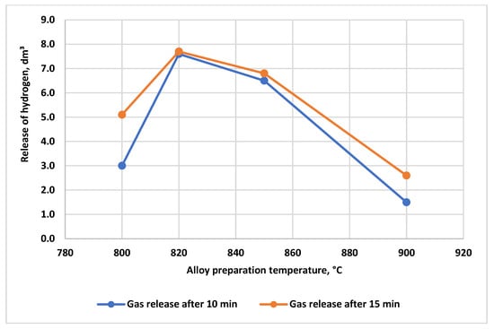
Figure 7.
Yield of the steam–hydrogen mixture during oxidation of alloy No. 2.1 with a 3% HCl solution as a function of the melting temperature regime; alloy-to-acid solution ratio = 1:100 (5 g alloy, 500 mL of 3% HCl).
For applications requiring rapid and intense thermogas impact on asphalt–resin–paraffin deposits (ARPD) in the near-wellbore zone, the optimal alloy production parameters are a melting temperature of 825 °C and a melt holding time of 30 min.
At melting temperatures of 750 °C and 900 °C, the yield of the steam–hydrogen mixture is significantly lower. At 800 °C, the total gas yield is higher; however, the peak gas release rate is smoothed, and the process is prolonged over time. Thus, the 825 °C/30 min regime is optimal for applications requiring fast and intense thermogas action on ARPD and clogging formations in the near-wellbore zone.
Figure 8 summarizes the influence of the main factors on the yield of the steam–hydrogen mixture for alloy No. 2.1.
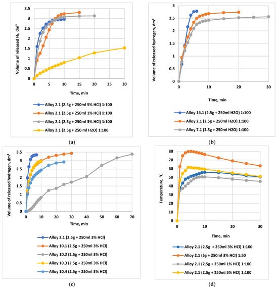
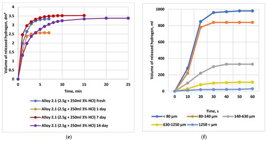
Figure 8.
Dependence of the evolved hydrogen volume and the temperature rise in the reaction medium on HCl concentration, activator content, alloy powder particle size (dispersion), and alloy storage time. Note: Comparative curves are presented for an alloy-to-oxidizing medium ratio of 1:100 (2.5 g of alloy in 250 mL of distilled H2O or HCl solution). (a) Dependence of the evolved hydrogen volume on the HCl concentration during interaction with alloy No. 2.1, in comparison with distilled water.  water
water  1% HCI
  3% HCI
  5% HCI; (b) Curves showing the dependence of the evolved hydrogen volume on the content of the activating additive in alloys No. 14.1, No. 7.1, and No. 2.1 during their interaction with water; (c) Dependence of the evolved hydrogen volume on the content of the activating additive during the interaction of alloys No. 2.1, No. 10.1, No. 10.3, No. 10.4, and No. 10.2 with a 3% HCl solution.
  1—alloy No. 2.1
  2—alloy No. 10.1
  4—alloy No. 10.3
  3—alloy No. 10.4
  5—alloy No. 10.2; (d) Dependence of the heating temperature of the oxidation reaction medium on the hydrochloric acid concentration; (e) Dependence of the volume of evolved hydrogen on the storage time of the alloy: hydrogen yield during the interaction of alloy No. 2.1 with a 3% HCl solution; (f) Effect of the particle size (powder dispersity) of alloy No. 2.1 on the time-dependent hydrogen yield during its interaction with water at 25 °C (1 g of alloy in 100 mL of water).
water 1% HCI 3% HCI 5% HCI; (b) Curves showing the dependence of the evolved hydrogen volume on the content of the activating additive in alloys No. 14.1, No. 7.1, and No. 2.1 during their interaction with water; (c) Dependence of the evolved hydrogen volume on the content of the activating additive during the interaction of alloys No. 2.1, No. 10.1, No. 10.3, No. 10.4, and No. 10.2 with a 3% HCl solution. 1—alloy No. 2.1 2—alloy No. 10.1 4—alloy No. 10.3 3—alloy No. 10.4 5—alloy No. 10.2; (d) Dependence of the heating temperature of the oxidation reaction medium on the hydrochloric acid concentration; (e) Dependence of the volume of evolved hydrogen on the storage time of the alloy: hydrogen yield during the interaction of alloy No. 2.1 with a 3% HCl solution; (f) Effect of the particle size (powder dispersity) of alloy No. 2.1 on the time-dependent hydrogen yield during its interaction with water at 25 °C (1 g of alloy in 100 mL of water).
As shown in Figure 8a, the transition from distilled water to a 3% HCl solution increases the total hydrogen yield by a factor of 1.5–2.5 and significantly enhances conversion; a 3% acid concentration provides nearly 95–98% conversion within 5–10 min. Increasing the HCl concentration to 5% makes it possible to reach the theoretically maximum hydrogen yield (100%). However, compared with 3% HCl, the hydrogen yield increases only marginally (by no more than 3–5%), while acid consumption rises by 66.67%, making the use of a 5% HCl solution economically inefficient.
Therefore, the use of 3% HCl represents an optimal compromise between high reaction efficiency (90–95% hydrogen yield) and operational costs.
Figure 8b,c illustrate the dependence of the evolved hydrogen volume on the content of activating additives (alloys No. 14.1, No. 7.1, and No. 2.1) during the interaction of the alloys with water. The highest hydrogen yield and generation rate are observed for alloys containing 5% Ga and 2.5–5% In (alloys No. 2.1 and No. 7.1), whereas a reduction in Ga content to 0.5% leads to a sharp decrease in the reaction rate (alloy No. 10.2).
Figure 8d shows the dependence of the heating temperature of the reaction medium during oxidation on the concentration of hydrochloric acid. The temperature reaches 65–95 °C at alloy-to-acid ratios of 1:25–1:50, which significantly enhances the thermohydraulic effect.
Figure 8e highlights the decisive role of powder dispersity. For particle sizes below 80 µm, the hydrogen yield at 25 °C reaches 980 mL g−1, whereas for particles of 1250 µm it is only 30 mL g−1. Increasing the reaction temperature to 60 °C substantially mitigates the effect of particle size, while simultaneously increasing the overall hydrogen yield.
The hydrogen yield relative to the theoretical maximum during alloy oxidation in water at 50 °C, compared with oxidation in a 3 wt.% HCl aqueous solution at 25 °C, as a function of melting regimes and alloy composition, is presented in Table 6.
Table 6.
Hydrogen yield relative to the theoretical maximum (%) during oxidation of alloys in water (50 °C) and in 3 wt.% HCl (25 °C), depending on melting regime and alloy composition (mean values, n ≥ 3).
The obtained results demonstrate that the rate, volume, and pattern of gas evolution can be deliberately controlled by selecting the melting regime, alloy composition, HCl concentration, powder dispersity, and phase ratio.
Alloys No. 2.1 and No. 7.1 are the most promising for thermogasochemical treatment of the near-wellbore zone, as they provide a high initial reaction rate and a pronounced thermal effect.
3.5. Measurement of Heat and Gas Release During Oxidation of Alloys by Natural Formation Water from the Karazhanbas Field
To assess the behavior of the alloys under conditions as close as possible to field operation, formation waters from oilfields in Western Kazakhstan (Karazhanbas, Altykul, and Botakhan) were used as the oxidizing media. Formation waters represent complex multicomponent systems characterized by high mineralization (15.34–215,600 mg/dm3), elevated chloride content (up to 159.75 g/L), the presence of sulfates and bicarbonates, various cations (Ca2+, Mg2+, Na+, etc.), as well as petroleum products (up to 4500 mg/L) and organic compounds. The characteristics of the collected samples are presented in Table 7 and Table 8.
Table 7.
Characteristics of reservoir waters of Western Kazakhstan fields.
Table 8.
Cation content in Karazhanbas reservoir water.
Chloride (Cl−), sulfate (SO42−), and bicarbonate (HCO3−) anions exhibit high corrosive activity and are capable of destroying the passivating Al2O3 oxide film on the alloy surface, thereby accelerating hydrogen and heat generation. At the same time, high concentrations of Ca2+ and Mg2+ may lead to the formation of insoluble precipitates that block active reaction sites, while elevated sulfate and HCO3− contents can shift the thermodynamics of the reaction toward a reduced H2 yield [30,31,37]. The most intense gas evolution is observed in waters with high total mineralization and high chloride content.
Water samples were collected at the inlet of the booster pumping station (BPS), as well as from wells No. 5025, No. 8425, No. 897, No. 1783, and No. 3817 (Karazhanbas field), No. 102 (Altykul field), and No. 121 (Botakhan field). Based on these waters, HCl solutions of various concentrations (1–5 wt.%) were prepared.
Figure 9a–c presents comparative kinetic curves of hydrogen evolution during the interaction of alloys No. 1.2 and No. 2.1 with formation waters from wells No. 5025 and No. 8425 (Karazhanbas field), in comparison with 1–3 wt.% HCl solutions (alloy-to-solution ratio 1:100). When pure formation water is used, the hydrogen yield relative to the theoretical value averages 38.9%; the reaction starts after 30–60 s and lasts 20–30 min, with more than 60% of the total gas volume released within the first 3–5 min. Upon addition of HCl, the conversion increases to 95–99% within 10 min, confirming the stimulating effect of chlorides on the destruction of the passive oxide layer.
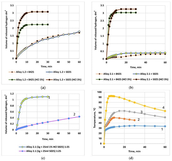
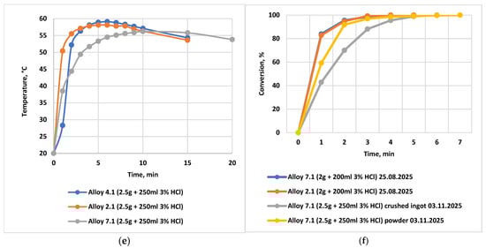
Figure 9.
Dependence of the volume of evolved hydrogen and the temperature rise in the reaction medium on the HCl concentration in formation water, the content of activating additives, the powder particle size of the alloy, and the alloy storage time. Water sampled from well No. 5025, Karazhanbas field. (a) Dependence of the volume of evolved hydrogen during the interaction of the alloys with formation waters from the Karazhanbas field at 25 °C (alloy: solution ratio = 1:100; 2.5 g of alloy and 250 mL of H2O or HCl). Alloy No. 1.2: formation water from wells No. 8425 and No. 5025 (curves 1 and 2), and 3 wt.% HCl solution (curves 3 and 4); (b) Dependence of the volume of evolved hydrogen during the interaction of the alloys with formation waters from the Karazhanbas field at 25 °C (alloy: solution ratio = 1:100; 2.5 g of alloy and 250 mL of H2O or HCl). Alloy No. 2.1: formation water from wells No. 8425 and No. 5025 (curves 1 and 2), and 3 wt.% HCl solution (curves 3 and 4).; (c) Dependence of the volume of evolved hydrogen during the interaction of alloy No. 2.1 with formation water from the Karazhanbas field at 25 °C. Comparison of formation water from well No. 5025 (curve 2) with a 1 wt.% HCl solution (curve 1); alloy: water ratio = 1:25; (d) Temperature rise in the oxidizing reaction medium during the interaction of alloy No. 2.1 with a 1 wt.% HCl solution prepared using formation water from the Karazhanbas DNPS at 25 °C, as a function of the alloy-to-acid volume ratio (acid volume = 250 mL): 1–1.25 g alloy (1:200); 2–2.5 g alloy (1:100); 3–5.0 g alloy (1:50); 4–10.0 g alloy (1:25); (e) Temperature rise in the oxidizing reaction medium during the interaction of alloys No. 2.1, No. 4.1, and No. 7.1 with a 3 wt.% aqueous HCl solution prepared using formation water; (f) Conversion of the reaction of alloy No. 7.1 with 3 wt.% HCl:  ingot stored for 70 days and then crushed into powder;
  powder stored for 70 days;
  freshly prepared powder.
ingot stored for 70 days and then crushed into powder; powder stored for 70 days; freshly prepared powder.
Figure 9d illustrates the dependence of the reaction-medium heating temperature on the alloy-to-solution ratio during oxidation of alloy No. 2.1 with a 1 wt.% HCl solution prepared using formation water from the booster pumping station (BPS, Karazhanbas). At ratios of 1:200, 1:100, 1:50, and 1:25, the temperature after 10 min reaches 34.5 °C, 50.5 °C, 60.1 °C, and 92.3 °C, respectively. The maximum thermohydraulic effect is observed at a ratio of 1:25.
Figure 9e compares the heating temperature during the interaction of alloys No. 2.1, No. 4.1, and No. 7.1 with a 3 wt.% HCl solution prepared using water from well No. 5025. The highest heating (up to 70–80 °C) is characteristic of alloys with a high content of activators (No. 2.1 and No. 7.1), which correlates with their increased reactivity.
Figure 9f demonstrates the stability of alloy activity during storage: the conversion of alloy No. 7.1 reacting with 3 wt.% HCl shows virtually no decrease after 70 days of storage (both in ingot and powder forms), confirming the feasibility of long-term storage and transportation.
The process conversion increases with increasing water mineralization: the highest efficiency is observed for DPS (Karazhanbas) waters and highly mineralized samples (Botakhan well No. 121). For stable and reproducible reaction conditions, a recommended alloy:HCl ratio is 1:50. When an excess of water is used (>150 mL per 1 g of alloy), both the hydrogen yield and the reaction heat decrease noticeably.
The amount of released heat was calculated using the heat balance equation:
where m—mass of water, kg;
Q = C·∆T·m, kJ
- C—specific heat capacity of water, 4.183 kJ/kg·K;
- ∆T = Tk − T0—temperature difference between the final and initial temperatures, °C (K).
Table 9 and Table 10 present the calculated values of the reaction heat in distilled water and formation waters with HCl additives. In distilled water, the heat release Q varies from 17,765 to 67,973 kJ/kg, corresponding to heating up to 38.8–92.5 °C. In formation waters with added HCl, the released heat increases to 73,150 kJ/kg (at 3–5% HCl and an alloy-to-solution ratio of 1:25), while the heating temperature reaches up to 95 °C. When 5% HCl solutions are used, the heat release is, on average, six times higher than that observed in pure water.
Table 9.
Heat of reaction during the interaction of multicomponent alloys of light and dispersed metals with HCl solutions in distilled water at 25 °C.
Table 10.
Heat of reaction during the interaction of multicomponent alloys of light and dispersed metals with HCI solutions in the reservoir water of deposits in Kazakhstan at 25 °C.
The hydrogen evolution rate (mL/g·min) for alloy No. 2.1 during oxidation with 5% HCl solutions based on highly mineralized formation waters of Western Kazakhstan is shown in Figure 10. The maximum rate of 1100 mL/g·min and completion of the reaction within 5 min are observed for the water from the Botakhan field (well No. 121, mineralization 215,600 mg/dm3). This behavior is attributed to the high chloride content and the absence of blocking precipitates, which facilitates rapid hydrogen generation.
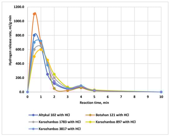
Figure 10.
Hydrogen evolution rate during the reaction of alloy No. 2.1 with 5% HCl solutions in formation waters of the Western Kazakhstan oil fields.
Studies show that the use of acidified formation waters (without additional external heating) makes it possible to achieve stable and intensive gas and heat generation with a high degree of hydrogen yield. This significantly enhances the practical value of activated Al–Ga–In–Sn alloys for thermo-gas-chemical treatment of the near-wellbore zone of high-viscosity oil wells.
4. Conclusions
- Changes in the structure and properties of activated Al–Ga–In–Sn alloys depending on the nature and amount of the introduced additives were revealed. The microstructure of the alloys and their oxidation products was studied using scanning electron microscopy with energy-dispersive X-ray spectroscopy (SEM/EDXs) employing an INCA ENERGY spectrometer (Oxford Instruments) installed on a JEOL Superprobe-733 electron probe microanalyzer, operated at an accelerating voltage of 25 kV and a probe current of 25 nA. Based on the microstructural analysis, the phase constituents of the alloys located at aluminum grain boundaries were identified. The microstructural analysis confirmed that the alloys are compositionally heterogeneous, with eutectic particles concentrated along the grain boundaries. During the crystallization of activated aluminum under nonequilibrium conditions, favorable structural states are formed (grain refinement of the alloy), leading to the formation of a large number of micro-galvanic elements. This is responsible for the sharp decrease in mechanical strength and the high reactivity of the alloys. The tensile strength decreases from 5.85 MPa for pure aluminum to 0.103 MPa for the quaternary alloy Al + 3 wt.% Ga + 3 wt.% In + 3 wt.% Sn.
- The thermodynamic instability of activated aluminum enables hydrogen generation at high and controllable rates. The high reactivity and versatility of multicomponent Al–Ga–In–Sn alloys ensure efficient hydrogen production and heat release in various aqueous media, including fresh water and formation water. The reaction proceeds rapidly and typically reaches completion within the first 5–10 min after contact of the alloy with the oxidizing medium.
- It has been shown that the kinetics of the Al–water reaction under ambient conditions are strongly influenced by the alloy composition, the concentration of activating metals, physicochemical properties of the medium, mineralization, salinity, pH level, and melting regimes. The use of a mildly acidic medium (1–5 wt.% HCl solution) optimizes the process, providing a hydrogen yield of 95–100% of the theoretical maximum. Under these conditions, the temperature of the aqueous phase increases to 55–95 °C depending on the alloy-to-solution ratio and acid concentration. The intense heat and gas evolution are attributed to the eutectic nature of the Al–Ga–In–Sn system.
- The highest thermal effect (67,973.7–73,150 kJ/kg) was achieved for the alloy composition Al 90 wt.%—Ga 5 wt.%—In 2.5 wt.%—Sn 2.5 wt.% at an alloy-to-acid ratio of 1:25. Notably, this formulation allows a reduction in the content of expensive gallium and indium without compromising efficiency. The intense release of heat and steam–hydrogen mixture is explained by the eutectic nature of the Al–Ga–In–Sn system. The mechanism involves mechanical fragmentation, formation of a highly reactive interfacial boundary with a large surface area, and the generation of micro-galvanic couples within the aluminum matrix, which eliminates the induction period.
- The ability to generate hydrogen and heat without external heating highlights the potential of these alloys for autonomous and mobile energy systems, as well as for thermochemical treatment in the oil and gas industry. Previous pilot field tests [34] demonstrated that the application of specific alloy compositions (Rau-85 alloy) for oil well stimulation results in a significant increase in well productivity and a multiple growth in oil production, particularly within the first 24 h after treatment.
Author Contributions
Conceptualization, G.B. and R.S.; methodology, G.B. and N.L.; software, G.B., R.S. and Y.B.; formal analysis, Y.P. (Yelena Panova); investigation, N.L., R.S., Y.P. (Yerkebulan Pulatov), Y.P. (Yelena Panova), A.M. (Asset Makhanov), A.M. (Askar Malbagarov) and Y.B.; resources, G.B. and B.K.; data curation, G.B., Y.P. (Yerkebulan Pulatov), Y.P. (Yelena Panova), A.M. (Asset Makhanov), A.M. (Askar Malbagarov) and N.L.; writing—original draft preparation, G.B. and N.L.; writing—review and editing, N.L.; visualization, A.M. (Asset Makhanov), Y.P. (Yerkebulan Pulatov), A.M. (Askar Malbagarov), Y.B. and Y.P. (Yelena Panova); supervision, G.B.; project administration, G.B., B.K.; funding acquisition, G.B. and R.S. All authors have read and agreed to the published version of the manuscript.
Funding
This research was funded by the Committee of Science of the Ministry of Science and Higher Education of the Republic of Kazakhstan (Grant No. BR24992868).
Data Availability Statement
The original contributions presented in this study are included in the article. Further inquiries can be directed to the corresponding author.
Conflicts of Interest
Authors Galina Boiko, Raushan Sarmurzina, Nina Lyubchenko, Bagdaulet Kenzhaliyev, Asset Makhanov, Yerkebulan Pulatov, Askar Malbagarov, Yelena Boiko were employed by the company Institute of Metallurgy and Ore Benefication JSC. The remaining authors declare that the research was conducted in the absence of any commercial or financial relationships that could be construed as a potential conflict of interest. The company had no role in the design of the study; in the collection, analyses, or interpretation of data; in the writing of the manuscript, or in the decision to publish the results.
Abbreviations
The following abbreviations are used in this manuscript:
| HO | Heavy oil |
| ARPD | Asphalt–resin–paraffin deposits |
| NWZ | Near-wellbore zone |
| EOR | Enhanced oil recovery |
| CSS | Cyclic steam stimulation |
| SAGD | Steam-assisted gravity drainage |
| CHOPS | Cold heavy oil production with sand |
| VAPEX | Vapor extraction using solvents |
| SAP | Solvent-assisted processes |
| THAI | Combination of in situ combustion and horizontal well production |
| CHTBS | Combined hydrogen and thermobarochemical stimulation |
| BSE | Backscattered electron |
| SE | Secondary electron |
References
- Li, X.; Liu, H.; Li, Q.; Xu, Y.; Zhao, S.; Liu, X.; Liu, Q. Solvent-Dependent Recovery Characteristic and Asphaltene Deposition during Solvent Extraction of Heavy Oil. Fuel 2020, 263, 116716. [Google Scholar] [CrossRef]
- Ibragimov, N.G.; Guseinov, S.I.; Sayfullin, R.S.; Beloglazov, I.N.; Karagandaev, R.I. Oslovneniya v Neftedobyche; Monograph; Ufa State Petroleum Technical University Press: Ufa, Russia, 2003; 302p, Available online: https://f.eruditor.link/file/768092/ (accessed on 27 November 2025).
- Roshchin, P.V.; Kireev, I.I.; Demin, S.V. Intensifikatsiya Dobychi Vysokovyazkoy Nefti. Neftegaz.RU 2020; pp. 88–91. Available online: https://magazine.neftegaz.ru/articles/nefteservis/547393-intensifikatsiya-dobychi-vysokovyazkoy-nefti/ (accessed on 27 November 2025).
- Nasr, T.N.; Beaulieu, G.; Holbeck, H.; Heck, G.A. Novel Expanding Solvent-SAGD Process “ES-SAGD”. J. Can. Petrol. Technol. 2003, 42, 13–16. [Google Scholar] [CrossRef]
- Zhao, D.V.; Wang, D.; Gates, I.D. Optimized Solvent Steam Flooding Strategy for Recovery of Thin Heavy Oil Reservoirs. Fuel 2013, 112, 50–59. [Google Scholar] [CrossRef]
- Mukhtanov, B.M. Application of Thermal Methods in the Republic of Kazakhstan: Current Projects and Prospects. SOCAR Proc. 2021, 1, 114–123. Available online: https://proceedings.socar.az/uploads/pdf/67/114_123_OGP20210100488.pdf (accessed on 27 November 2025). [CrossRef]
- Kravchenko, O.V. Increase of Oil-and-Gas Bearing Rocks Permeability with the Help of Hydrogen Activation. East.-Eur. J. Enterp. Technol. 2013, 1, 21–25. Available online: http://journals.uran.ua/eejet/article/view/9189/7984 (accessed on 25 November 2025).
- Kravchenko, O.V.; Veligotsky, D.A.; Avramenko, A.N.; Khabibullin, R.A. An improved technology of a complex influence on productive layers of oil and gas wells. East.-Eur. J. Enterp. Technol. 2014, 6, 4–9. [Google Scholar] [CrossRef]
- Du, B.D.; He, T.T.; Liu, G.L.; Chen, W.; Wang, Y.M.; Wang, W.; Chen, D.M. Al–water reactivity of Al–Mg–Ga–In–Sn alloys used for hydraulic fracturing tools. Int. J. Hydrogen Energy 2018, 43, 7201–7215. [Google Scholar] [CrossRef]
- Ma, M.; Duan, R.; Ouyang, L.; Zhu, X.; Chen, Z.; Peng, C.; Zhu, M. Hydrogen storage and hydrogen generation properties of CaMg2-based alloys. J. Alloys Compd. 2017, 691, 929–935. [Google Scholar] [CrossRef]
- Xiao, F.; Yang, R.; Liu, Z. Active aluminum composites and their hydrogen generation via hydrolysis reaction: A review. Int. J. Hydrogen Energy 2022, 47, 365–386. [Google Scholar] [CrossRef]
- Bai, W.; Qiao, Y.; Wang, C.; Li, H.; Zhang, X.; Zhang, C.; Yao, M. Comprehensive Assessments of a Novel Aluminum-Fueled Energy Storage System. Energy Convers. Manag. 2022, 266, 115615. [Google Scholar] [CrossRef]
- Su, M.; Wang, H.; Xu, H.; Chen, F.; Hu, H.; Gan, J. Enhanced Hydrogen Production Properties of a Novel Aluminum-Based Composite for Instant On-Site Hydrogen Supply at Low Temperature. Int. J. Hydrogen Energy 2022, 47, 9969–9985. [Google Scholar] [CrossRef]
- Zhang, X.; Wang, L.; Tao, G.; Guo, R.; Jiawei, F.; Zhang, J.F.; Mao, H. Hydrogen Production from Aluminum–Water Reactions at Low Temperatures: Based on an In Situ Two-Powders of Different Particle Sizes. Front. Energy Res. 2024, 12, 1441155. [Google Scholar] [CrossRef]
- An, Q.; Jin, Z.; Li, N.; Wang, H.; Schmierer, J.; Wei, C.; Hu, H.; Gao, Q.; Woodall, J.M. Study on the Liquid Phase-Derived Activation Mechanism in Al-Rich Alloy Hydrolysis Reaction for Hydrogen Production. Energy 2022, 247, 123489. [Google Scholar] [CrossRef]
- Ouyang, L.; Liu, M.; Chen, K.; Liu, J.; Wang, H.; Zhu, M.; Yartys, V. Recent Progress on Hydrogen Generation from the Hydrolysis of Light Metals and Hydrides. J. Alloys Compd. 2022, 910, 164831. [Google Scholar] [CrossRef]
- Ouyang, L.; Jiang, J.; Chen, K.; Zhu, M.; Liu, Z. Hydrogen Production via Hydrolysis and Alcoholysis of Light Metal-Based Materials: A Review. Nano-Micro Lett. 2021, 13, 134. [Google Scholar] [CrossRef]
- Qiao, D.; Lu, Y.; Tang, Z.; Fan, X.; Wang, T.; Li, T.; Liaw, P.K. Superior Hydrogen-Generation Performance of Multicomponent Aluminum Alloys via Hydrolysis Reaction. Int. J. Hydrogen Energy 2018, 43, 3527–3537. [Google Scholar] [CrossRef]
- Meng, A.; Sun, Y.; Cheng, W.; Zhai, Z.; Chong, Z.; Jiang, L.; Ma, X. Hydrogen Production Performance of an Al–Ga–In–Sn Quaternary Alloy. Mater. Today Sustain. 2023, 21, 100284. [Google Scholar] [CrossRef]
- Sarmurzina, R.G.; Boiko, G.I.; Kenzhaliyev, B.K.; Karabalin, U.S.; Lyubchenko, N.P.; Kenyaikin, P.V.; Ilmaliyev, Z.B. Coagulants for Water Based on Activated Aluminum Alloys. Glob. J. Environ. Sci. Manag. 2023, 9, 673–690. [Google Scholar] [CrossRef]
- Wang, W.; Chen, D.M.; Yang, K. Investigation on microstructure and hydrogen generation performance of Al-rich alloys. Int. J. Hydrogen Energy 2010, 35, 12011–12019. [Google Scholar] [CrossRef]
- Wei, C.; Liu, D.; Xu, S.; Cui, T.; An, Q.; Liu, Z.; Gao, Q. Effects of Cu Additives on the Hydrogen Generation Performance of Al-Rich Alloys. J. Alloys Compd. 2018, 738, 105–110. [Google Scholar] [CrossRef]
- Jin, Z.; Wang, H.; Shi, J.; Wang, H.; Gao, X.; Gao, Q.; Sun, X. Unveiling the Role of Indium and Tin in Al–Ga-Based Alloys for On-Demand Hydrogen Supply: From Simulation to Validation. J. Power Sources 2023, 554, 232268. [Google Scholar] [CrossRef]
- Meng, A.; Sun, Y.; Cheng, W.; Zhai, Z.; Jiang, L.; Chong, Z.; Chen, Y.; Wu, A. Mechanism of hydrogen generation from low melting point elements (Ga, In, Sn) on aluminum alloy hydrolysis. Int. J. Hydrogen Energy 2022, 47, 39364–39375. [Google Scholar] [CrossRef]
- Baigaziev, M.T.; Sarsenbekov, N.D.; Boiko, G.I.; Sarmurzina, R.G.; Lyubchenko, N.P.; Karabalin, U.S.; Akchulakov, B.U. Research of influence of activated aluminum alloys for the cores saturated with oil of Kazakhstan fields. Oil Ind. 2018, 7, 68–89. Available online: https://oil-industry.net/Journal/archive_detail.php?ID=11135&art=231968 (accessed on 20 January 2026). [CrossRef]
- An, Q.; Hu, H.; Li, N.; Liu, D.; Xu, S.; Liu, Z.; Gao, Q. Effects of Bi composition on microstructure and Al-water reactivity of Al-rich alloys with low-In. Int. J. Hydrogen Energy 2018, 43, 10887–10895. [Google Scholar] [CrossRef]
- Xiao, F.; Guo, Y.; Yang, R.; Li, J. Hydrogen Generation from Hydrolysis of Activated Magnesium/Low-Melting-Point Metal Alloys. Int. J. Hydrogen Energy 2018, 43, 1366–1373. [Google Scholar] [CrossRef]
- Wang, W.; Zhao, X.M.; Chen, D.M.; Yang, K. Insight into the Reactivity of Al–Ga–In–Sn Alloy with Water. Int. J. Hydrogen Energy 2012, 37, 2187–2194. [Google Scholar] [CrossRef]
- He, T.; Wang, W.; Chen, W.; Chen, D.; Yang, K. Reactivity of Al-Rich Alloys with Water Promoted by Liquid Aluminum Grain Boundary Phases. J. Mater. Sci. Technol. 2016, 32, 397–403. [Google Scholar] [CrossRef]
- Wang, W.; Chen, W.; Zhao, X.M.; Chen, D.M.; Yang, K. Effect of composition on the reactivity of Al-rich alloys with water. Int. J. Hydrogen Energy 2012, 37, 18672–18678. [Google Scholar] [CrossRef]
- Lu, J.; Yu, W.; Tan, S.; Wang, L.; Yang, X.; Liu, J. Controlled hydrogen generation using interaction of artificial seawater with aluminum plates activated by liquid Ga–In alloy. RSC Adv. 2017, 7, 30839–30846. [Google Scholar] [CrossRef]
- Sarmurzina, R.G.; Boiko, G.I.; Karabalin, U.S.; Tiesov, D.S.; Lyubchenko, N.P.; Baigaziev, M.T. Prospects for the Use of Hydrogen Energy in Technologies of Integrated Oil Treatment, Destruction of Abnormally Stable Water–Oil Emulsions, and Oil Sludges. Oil Gas Innov. 2019, 5, 26–31. (In Russian). Available online: https://neft-gaz-novacii.ru/ru/archive/104-2019/1907-05-2019 (accessed on 20 January 2026).
- Boiko, G.I.; Sarmurzina, R.G.; Galieva, N.P.; Karabalin, U.S.; Tiesov, D.S.; Akhanova, T.R.; Kenyaikin, P.V. Prospects for the Use of Energy-Accumulating Substances in Solving Environmental Problems of the Oil Industry. Bull. Oil Gas Ind. Kazakhstan 2023, 5, 128–154. (In Russian) [Google Scholar] [CrossRef]
- Sarmurzina, R.G.; Karabalin, U.S.; Dosmukhambetov, M.D.; Iskaziev, K.; Boiko, G.I.; Moldabekov, B.S.; Lyubchenko, N.P. Method for Treating the Bottomhole Formation Zone. Kazakhstan Innovative Patent KZ 31164, 16 May 2016. Bulletin No. 5. Available online: https://kz.patents.su/5-ip31164-cposob-obrabotki-prizabojjnojj-zony-plasta.html (accessed on 20 January 2026). (In Russian)
- Rebinder, P.A. Surface Phenomena in Disperse Systems. Colloid Chemistry. Selected Works; Nauka: Moscow, Russia, 1978; Available online: https://gse.ua/ru/biblioteka/stati/453-s-v-remizov.html (accessed on 20 January 2026). (In Russian)
- Kosolapov, V.A. Materials Science and Technology of Structural Materials; Vysshaya Shkola: Moscow, Russia, 2003. (In Russian) [Google Scholar]
- Liu, J.; Zhang, X.; Chen, M.; Li, L.; Zhu, B.; Tang, J.; Liu, S. DFT study on surface properties and dissolution trends of Al(100) surfaces doped with Zn, Ga, In, Sn, and Pb. Appl. Surf. Sci. 2011, 257, 4004–4009. [Google Scholar] [CrossRef]
- GOST R 58144-2018; Distilled Water Specifications. Distilled Water. Specifications. Federal Agency on Technical Regulation and Metrology (Rosstandart): Moscow, Russia, 2018.
Disclaimer/Publisher’s Note: The statements, opinions and data contained in all publications are solely those of the individual author(s) and contributor(s) and not of MDPI and/or the editor(s). MDPI and/or the editor(s) disclaim responsibility for any injury to people or property resulting from any ideas, methods, instructions or products referred to in the content. |
© 2026 by the authors. Licensee MDPI, Basel, Switzerland. This article is an open access article distributed under the terms and conditions of the Creative Commons Attribution (CC BY) license.