Abstract
Currently, lithium-ion battery packaging has poor sealing and positive and negative electrodes are easily damaged by humid environments; therefore, we design a structure in which the inner packaging uses HL-1029 silicone gel to wrap the lithium-ion battery, and the outer packaging is packed in a corrugated carton. According to the lithium-ion battery model and size, the thickness of HL-1029 inclusions was calculated, the packaging model was established, and the stress contour plot diagram of HL-1029 inclusions and lithium-ion batteries under the 1200 mm drop height and two drop postures in the finite element environment was analyzed; the maximum stress of the lithium-ion battery did not exceed the yield strength of its material. Based on the energy method, the reliability analysis of the final finite element simulation results is carried out. When the two drop postures are 1200 mm in height, the maximum stresses of the lithium-ion batteries are 4.367 MPa and 4.555 MPa, respectively, and the ratios of the hourglass of energy to the internal energy of the packaging system are 0.700% and 1.190%, respectively. Based on the finite element analysis results and reliability verification, HL-1029 inclusions can provide sufficient protection during lithium-ion battery transportation and have high recyclability.
1. Introduction
Green packaging refers to a packaging method that, while meeting the product’s packaging requirements during its lifecycle, minimizes harm to the ecological environment and human health, with low energy consumption [1]. It should adhere to principles of light weight, recyclability, renewability, and biodegradability in practical applications. Lithium-ion battery packaging typically involves the use of corrugated paper sheets to separate the batteries internally, with external packaging using wooden boxes, cardboard boxes, or plastic containers. However, regardless of the packaging form used, its sealing performance is generally poor and cannot provide effective protection to the battery’s terminals. During transportation, environmental factors such as humidity can potentially cause lithium batteries to explode and release toxic gases, potentially resulting in immeasurable harm [2,3,4]. Research into recyclable packaging for lithium batteries can help reduce safety risks and promote energy conservation and emission reduction.
Zhou tested lithium-ion battery modules at different voltages using three types of external short-circuit tests alongside an electrochemical–thermal model. He identified two primary risk modes and clarified when weak connections or fuses are the appropriate protection, showing that a protector’s trip time and arc-extinguishing ability are crucial. This work fills a gap in module-level short-circuit risk analysis and provides practical experimental and theoretical guidance for protection design [5]. Guo designed a 2D double-U expansion honeycomb structure. Using theory, numerical simulation and experiments, and comparing it with the conventional double-V design, the study shows how impact speed and indenter size affect its dynamic response; the double-U structure markedly suppresses stress concentrations, enhances the expansion effect, and improves energy absorption [6]. Gao systematically analyzed the low-speed impact response of a double-arrow honeycomb structure. By comparing deformation under high- and low-speed impacts, he developed and validated an analytical model for dynamic strength and energy absorption based on cell-collapse mechanisms. The study reveals how relative density and impact velocity influence mechanical performance, filling a gap in predicting the dynamic behavior of such expansion-type honeycomb structures under low-speed impact [7]. However, while these structural innovations significantly improve crashworthiness, they often involve complex manufacturing processes. Su prepared an h-BN/silicone gel composite insulator by physical modification and used molecular-dynamics simulations to reveal how BN doping alters the material’s microstructure, dielectric behavior, and breakdown performance. The insulator with 2% BN showed the best electrical, thermal, and mechanical properties [8]. He proposed DIGCNet, a deep learning framework that combines image generation, pattern classification, and metric prediction subnetworks to accurately identify deformation-mode domains of energy-absorbing structures and predict crashworthiness indicators. The framework determines optimal hyperparameters and enables structure optimization under deformation constraints, addressing the long-standing difficulty of quantifying and matching deformation modes with parameter domains [9]. Li addressed the frontal low-obstacle collision risk to EV battery packs by designing seven bioinspired honeycomb structures and evaluating their crashworthiness. The straw-stem–inspired design performed best; parametric optimization identified its optimal geometry and substantially reduced bottom-shell deformation and stress. This offers a bioinspired design concept and reliable numerical simulation and optimization methods for battery-pack collision protection [10]. Du developed a wood-inspired CSH-PVA composite using freeze-drying and chemical crosslinking. The material is lightweight yet strong, exhibits a negative Poisson’s ratio, and combines effective thermal insulation with flame retardancy; they showed excellent battery protection performance and offering a new multifunctional solution to thermal runaway and impact hazards in electronic device batteries [11]. Stephenson developed a design optimization method that combines machine learning with finite-element simulation to meet the in-plane impact protection needs of pouch cells. He designed an expansion type honeycomb sandwich protector and used an ANN to predict crashworthiness metrics. By coupling NSGA-II with TOPSIS for multi-objective optimization maximizing SEA while minimizing battery stress, he obtained a high-performance double-U expansion design, offering an efficient and accurate solution for EV battery impact protection [12]. Yang addressing the issue of thermal runaway propagation in lithium batteries, designed a battery cushioning pad based on compressed polyurethane foam materials. They conducted puncture tests on modules composed of soft pack battery cells at 100% state of charge (SOC), placing foam pads between the cells. The experimental results showed that polyurethane foam with flame-retardant additives or coatings significantly delayed the occurrence of chain thermal runaway. High-density polyurethane foam with multi-layer coatings made from fireproof materials and expandable materials was even more effective in completely blocking chain failure [13]. Liu addressed the poor barrier performance of paper-based lithium-ion battery packaging during thermal runaway by designing an aerogel felt. A thermal runaway evolution model was then established, using lithium-ion batteries at 30% SOC and 100% SOC as the study objects. Experimental results show that, as the aerogel felt thickness increases, its ability to isolate thermal runaway improves and the propagation rate of thermal runaway decreases [14]. Nevertheless, materials such as polyurethane foam and aerogel are difficult to recycle and are not environmentally friendly.
While existing studies have made significant contributions to structural crashworthiness and thermal safety, they often focus on isolated performance aspects. For instance, complex bio-inspired honeycomb structures face challenges regarding manufacturing costs and mass production, while traditional foam materials typically suffer from poor visibility. Crucially, current research generally overlooks a vital factor: sealing performance. Many porous structures capable of shock absorption fail to protect electrode terminals from moisture ingress. Since few market solutions simultaneously satisfy the demands for efficient impact protection, reliable moisture resistance, and recyclability, a comprehensive solution providing both physical protection and environmental isolation is urgently needed.
To address these limitations, this study proposes a novel green packaging structure that pioneers the application of HL-1029 silicone gel for lithium-ion battery packaging. In this design, HL-1029 silicone gel serves as the inner encapsulant, while corrugated cardboard is used for the outer casing. Unlike traditional materials, HL-1029 offers distinct technical advantages: superior sealing to prevent terminal oxidation in humid environments, excellent shock absorption, and high transparency for preliminary visual inspection of battery status. Furthermore, both the silicone gel and the corrugated box are fully recyclable. This design not only ensures transportation safety for standard 18650-type lithium-ion batteries but also provides a scalable packaging solution for small-scale energy storage devices which are required to meet high environmental standards, such as drone batteries, power banks, and laptop batteries.
2. Materials and Methods
The research object of this study is the 18650-type cylindrical lithium-ion battery (Shenzhen Liangpin Electronic Technology Co., Ltd., Shenzhen, China); this model was selected because it represents the most mature and universally standardized format in the global lithium-ion battery industry. These 18650-type lithium-ion batteries are extensively used in a wide range of applications, ranging from portable consumer electronics to high-power modules in electric vehicles and energy storage systems. Consequently, the volume of packaging material consumed for their transport is immense, making the development of green packaging for this specific model highly significant for environmental conservation.
Structurally, it has a capacity of 7400 mWh, a bottom diameter of 18 mm, a height of 65 mm, and a mass of 46 g. The operating temperature ranges are as follows: charging (10–45 °C), discharging (−20–60 °C), and storage (−20–50 °C). Its cylindrical geometry and terminal structure make it particularly sensitive to mechanical impact, serving as an ideal reference object for evaluating the protective performance of the proposed silicone gel encapsulation.
This paper adopts a combined theoretical and numerical approach to design and verify the green packaging structure. The research methodology follows three main steps. First, the packaging materials (HL-1029 silicone gel and corrugated cardboard) are selected and characterized based on their mechanical and environmental properties. Second, the structural dimensions specifically the thickness of the silicone encapsulant are determined through theoretical cushioning calculations to meet safety standards. Finally, finite element analysis is employed to simulate drop tests. This includes modeling geometry, verifying mesh independence, and analyzing stress distribution to validate the packaging’s protective performance and reliability.
2.1. Selection of Packaging Materials
Silicone gel is widely used for sealing and packaging electronic components. Owing to its inherent organic polymer advantages, silicone gel not only offers low surface tension, a low viscosity temperature coefficient, strong compressibility, and good gas permeability, but also delivers properties that are difficult for many inorganic materials to match: excellent high-/low-temperature resistance, outstanding electrical insulation, and strong oxidation resistance [15,16]. Just as importantly, this “all-rounder” material is non-toxic, odorless, and highly biocompatible, making it a rare “treasure” material [17].
In this study, we select HL-1029 (Shenzhen Huasheng Tongchuang Technology Co., Ltd., Shenzhen, China), a highly transparent potting silicone gel as shown in Figure 1. HL-1029 is a low-viscosity, two-component system that cures at room temperature; in recent years, it has been widely adopted for packaging precision electronic components and high-precision parts. Its key application parameters are listed in Table 1.
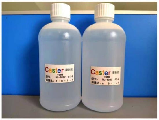
Figure 1.
HL-1029 silicone gel.

Table 1.
HL-1029 parameters.
In addition, HL-1029 is environmentally friendly and recyclable; it provides excellent cushioning; its high translucency affords clear visibility; and its high plasticity allows casting into virtually any shape. In our packaging design, the inner layer fully encapsulates the lithium-ion battery with HL-1029. Its waterproof, moisture-proof, and sealing and immobilizing characteristics effectively address the risk of thermal runaway caused by the battery’s exposed electrodes in humid transport environments [18,19,20].
Moreover, thanks to its material properties, used HL-1029 can be collected, granulated into fine particles, and (leveraging the like-dissolves-like principle for organics) it can be reused as a filler and raw additive blended with fresh HL-1029 during the next casting cycle, enabling true closed loop reuse. The concept is illustrated in Figure 2.
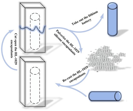
Figure 2.
Principle of HL-1029 silicone gel reuse and recycling.
Corrugated cartons feature substantial void volume within the paperboard flutes, giving them excellent shock absorption and cushioning to protect their contents from impact. Compared with wooden crates of the same volume, they are much lighter, which is why they are commonly used as outer packaging. Their printable surface also accommodates a variety of graphics for branding and presentation.
In accordance with the national standard GB/T 6543-2008 [21], this study adopts a single-wall-corrugated carton with C-flute, 4.000 mm thick. A schematic of the structure is shown in Figure 3.
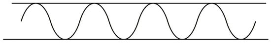
Figure 3.
Single corrugated carton structure.
2.2. Thickness Calculation of the HL-1029 Silicone Gel Encapsulant
The lithium-ion battery examined in this study has a mass of 46 g, and its fragility value, , is set to 180 G. According to the International Maritime Dangerous Goods (IMDG) Code and related transport regulations, lithium batteries fall under Class 9 dangerous goods, and the drop test height must be 1.200 m. Accordingly, the simulated drop height, , is set to 1200 mm.
When the battery is placed upright on the HL-1029 silicone gel, the effective cushioning area, , is the contact area between the battery bottom and the silicone gel. The calculation gives = 254 mm2. The maximum stress borne by the silicone gel is [22] as follows:
where is the maximum stress (kPa); is the mass of the lithium-ion battery (kg); is the fragility factor; is the gravitational acceleration (mm/s2); is the contact area (mm2).
Based on the constitutive behavior of the HL-1029 silicone gel, the stress–buffer coefficient curve is shown in Figure 4.
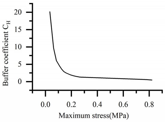
Figure 4.
Stress–buffer coefficient curve of HL-1029.
From the curve in Figure 4, we can see that, when the stress is 0.330 MPa, the corresponding cushioning coefficient is 1.300. The thickness of the HL-1029 encapsulant is then calculated as follows [22]:
where is the minimum encapsulant thickness (mm); is the cushioning coefficient; is the drop height (mm).
Therefore, the minimum encapsulant thickness must be 8.700 mm to satisfy the cushioning requirement. Since lithium batteries are special hazardous goods, to enhance protection and avoid accidents arising from discrepancies between theoretical calculations and practical handling, a safety factor of 2.500 is adopted. The final encapsulant thickness is thus set to 22 mm.
2.3. Simulation Analysis of Lithium-Ion Battery Packaging
2.3.1. Modeling of the Lithium-Ion Battery Packaging
The 18650 lithium-ion battery studied here has a circular base with diameter = 18 mm and a height = 65 mm. The outer carton adopts a single-wall, C-flute-corrugated box with a wall thickness of 4 mm. Based on the foregoing thickness calculation for the HL-1029 encapsulant, the overall package comprising the battery, the HL-1029 encapsulation, and the outer carton has the following dimensions: length = 70 mm, width = 70 mm, and height = 117 mm. The dimensional drawing and exploded view are shown in Figure 5.
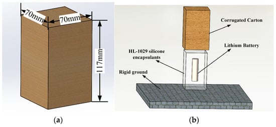
Figure 5.
Three-dimensional modeling of lithium-ion batteries. (a) Dimensions of the lithium-ion battery package; (b) lithium-ion battery package exploded view.
2.3.2. Drop Simulation of the Packaging Structure
Finite element simulation helps pinpoint key design parameters, weed out noncompliant concepts, and guide both design and testing. It also addresses situations where physical testing is prohibitively expensive or experimental conditions cannot be met. While certain critical events may be difficult for humans to capture during testing, finite element analysis is unconstrained and can record such data with precision. This study uses ANSYS Workbench (Version 2024 R1), which streamlines material assignment, contact definitions, and mesh generation for the model, and offers powerful post-processing capabilities.
- (1)
- Model import
We saved the packaging structure drawn in the SolidWorks software (Version 2022) as an .xt file, then imported it into the Explicit Dynamics module of ANSYS Workbench. Since the designed lithium-battery package is a rectangular cuboid, two drop orientations were simulated: an face A drop and a face B drop, as shown in Figure 6 and Figure 7.
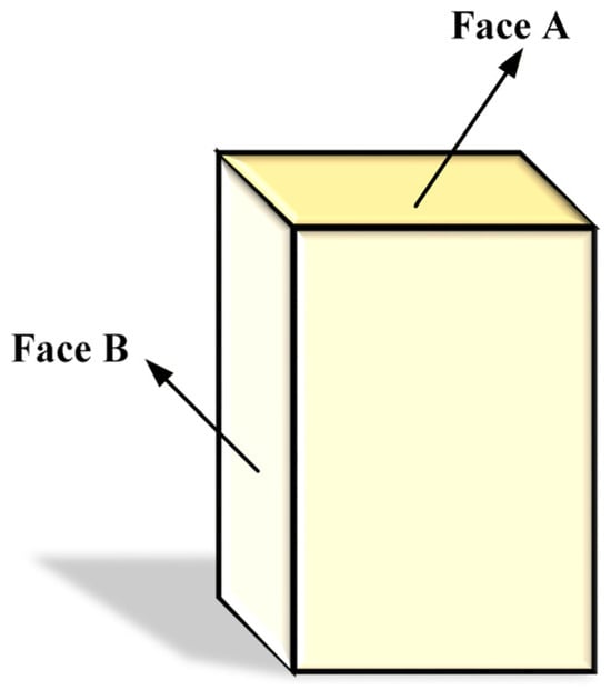
Figure 6.
Schematic diagram of face A and face B of the package.
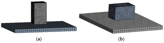
Figure 7.
Schematic diagram of dropping posture of package. (a) Face A drop diagram; (b) face B drop diagram.
- (2)
- Set material properties
The packaging structure consists of a corrugated carton, an HL-1029 silicone gel, the lithium-ion battery, and a rigid ground. The lithium-ion battery is mainly composed of components such as the positive and negative electrodes, safety valve, sealing ring, and casing [23,24,25,26,27]. For ease of analysis, the battery casing is selected as the primary object of study.
The HL-1029 silicone gel exhibits typical hyperelastic behavior involving large deformations and non-linear stress–strain relationships. Consequently, a linear elastic model is inapplicable. In this study, the Mooney-Rivlin 2 Parameter hyperelastic constitutive model was selected to characterize the material. The Mooney-Rivlin 2 parameter model is a classic constitutive model for hyperelastic materials. It is specifically utilized to characterize the elastic mechanical behavior of such materials under large deformation conditions and is widely applied in engineering simulations, such as finite element analysis. The model is fundamentally defined by its strain energy density function, [28].
where is the strain energy density (J/m3); and are strain invariant; and are material constants (MPa); 1 is the incompressibility parameter; is the volume ratio.
Specifically, the material parameters and were derived from the experimental data obtained via the uniaxial compression test of the HL-1029 silicone gel. The stress–strain curve resulting from this test is presented in Figure 8. Based on the curve fitting, the final determined parameters are = 0.056 MPa and = 0.006 MPa.
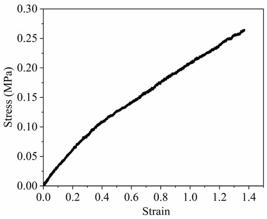
Figure 8.
Stress–strain curve of HL-1029 silicone gel.
Meanwhile, in actual physical scenarios, corrugated cardboard possesses orthotropic characteristics and dissipates kinetic energy through crushing and buckling deformation. In this study, to focus on the cushioning performance of the HL-1029 silicone gel, the corrugated carton is simplified as an isotropic linear elastic material. The simulated elastic box transmits a higher proportion of the impact energy to the internal structure. Consequently, verifying the reliability of the battery under these stricter simulation conditions ensures a sufficient safety margin for practical transportation, where the outer box contributes additional energy absorption.
Combining the material characteristics of the HL-1029 silicone gel and the corrugated cardboard discussed above, the material properties of the packaging structure are shown in Table 2.
Table 2.
Material attribute table.
- (3)
- Mesh generation
The primary focus of this study is to analyze the stress within the HL-1029 encapsulant and the lithium-ion battery, and it is important to consider the complex cylindrical geometry of the 18650 battery along with the curved surfaces of the silicone encapsulant; therefore, these two models were discretized using four-node linear tetrahedral solid elements. The remaining models were meshed using the software’s automatic generation settings, as shown in Figure 9. While hexahedral elements are commonly used for simple geometries, tetrahedral elements provide reliable automated meshing for curved boundaries, thereby ensuring accurate contact definition at the interface between the battery and the encapsulant.
Figure 9.
Schematic diagram of mesh elements. (a) Hexahedral element; (b) tetrahedral element.
To ensure calculation accuracy, a mesh independence verification was conducted. Preliminary simulations were performed with four different global element sizes: 2.50 mm, 3.00 mm, 3.50 mm, and 4.00 mm. As shown in Table 3, the analysis showed that refining the mesh from 3 mm to 2.50 mm percentage change in peak stress of less than 5%, indicating that the solution had converged. Therefore, a global element size of 3.00 mm was adopted for the final simulation to achieve an optimal balance between geometric fidelity and computational efficiency.
Table 3.
Mesh independence verification and percentage change in stress.
- (4)
- Solver controls
The drop simulation was performed using the Explicit Dynamics solver. To ensure numerical stability during the high-speed impact, the time integration step was automatically controlled based on the Courant Friedrichs Lewy (CFL) criterion.
Unlike hexahedral elements, standard linear tetrahedral elements do not typically exhibit zero energy hourglass modes. So, we monitored the energy ratio throughout the simulation.
- (5)
- Contact types and drop parameter settings
Since there is no connection between the HL-1029 encapsulant and the corrugated carton, their contact type is set to frictionless. The battery is encapsulated within HL-1029, so their contact type is set to bonded. Because simulating a drop from 1200 mm imposes high hardware requirements and leads to long solution times, the package is positioned 10 mm above the rigid ground, and we define the height already fallen as :
Subsequently, the velocity, , corresponding to a drop height of 1190 mm, was calculated according to the free fall formula; its magnitude is as follows [28]:
where is the initial velocity (mm/s); is the effective fall distance (mm).
The effect of air drag was not considered in the drop simulation. Theoretically, applying an initial velocity at a 10 mm gap is energetically equivalent to a full-height drop simulation in a vacuum. Since gravity remains active during the final 10 mm descent, the total kinetic energy at the moment of impact satisfies the law of conservation of energy. This approach aligns with standard transport protocols, such as ASTM D5276 [29] or the ISTA series, which characterize the test as a “Free Fall” event without mandating vacuum conditions. For a compact, dense package falling from 1200 mm, the energy dissipation due to drag is less than 1% and is therefore negligible.
3. Results
3.1. Drop Results Analysis
3.1.1. Analysis of Face A Drop Results of the Packaging Structure
After face A drops, the stress and deformation of the HL-1029 encapsulant are shown in Figure 10a,b. As shown in the figure, at 4 × 10⁻³ s, the encapsulant experiences its maximum stress, which is 0.264 MPa. The peak stress occurs at the bottom of the encapsulant but does not fracture. The stress and deformation of the lithium-ion battery during the face A drop test are illustrated in Figure 10c,d. As shown in the figure, the maximum stress on the lithium-ion battery reaches 4.367 MPa at 5 × 10⁻³ s, which occurs at the contact interface between the lithium-ion battery and the packaging. Typically, the outer casing of lithium batteries is made of nickel-plated steel, whose maximum yield strength is 132 MPa, far exceeding the stress exerted on the battery during the drop. Thus, the battery remains undamaged.
Figure 10.
Analysis of face A drop results (The red dashed lines in (b,d) are auxiliary positioning lines). (a) Stress contour plot of dropping inclusions of face A; (b) curve of stress on dropping inclusions of face A; (c) stress contour plot of dropping inclusions of face A; (d) curve of stress on dropping inclusions of face A.
3.1.2. Analysis of Face B Drop Results of the Packaging Structure
After face B drops, the stress and deformation of the HL-1029 encapsulant are shown in Figure 11a,b. As shown in the figure, at 4 × 10⁻³ s the encapsulant experiences its maximum stress, which is 0.401 MPa. The peak stress occurs at the bottom of the encapsulant but does not fracture. The stress and deformation of the lithium-ion battery in the B face drop are shown in Figure 11c,d. As shown in the figure, at 8 × 10⁻³ s the battery experiences its maximum stress, which is 4.555 MPa. The peak stress occurs on the side of the battery in contact with the encapsulant. This is much greater than the stress the battery experiences during the drop, and the battery is undamaged.
Figure 11.
Analysis of face B drop results (The red dashed lines in (b,d) are auxiliary positioning lines). (a) Stress contour plot of dropping inclusions of face B; (b) curve of stress on dropping inclusions of face B; (c) stress contour plot of dropping inclusions of face B; (d) curve of stress on dropping inclusions of face B.
3.2. Reliability Verification of Drop Simulation Results
Although the final simulation results show convergence, reliability verification is still required. The energy method can be used to assess whether the simulation results are reasonable [25,26]. In the software’s Solution Information module, we selected Momentum Summary and Energy Summary to observe the momentum curve and energy curve of the package during the drop.
3.2.1. Verification of Face A Drop Results
The momentum curve for the face A drop of the packaging structure is shown in Figure 12. Since the drop direction for face A is along the negative Y-axis, the package’s momentum and impulse in the X and Z directions are both zero. From the figure, the package’s initial momentum is negative; as the package falls, the magnitude of the momentum gradually decreases, while the impulse begins to increase. When the momentum curve crosses zero on the vertical axis and then increases in the positive Y direction, it indicates that the package has completed impact with the rigid ground and has entered the rebound phase.
Figure 12.
Momentum summary of the package on face A (The red dashed lines in the figure are auxiliary positioning lines). (a) Impulse curve of face A drop; (b) momentum curve of face A drop.
The energy curve of the face A drop is shown in Figure 13. From the figure, during the drop of the packaging structure, the internal energy curve and the kinetic energy curve remain unchanged at the beginning, because the package is still in free fall and has not yet contacted the ground. Subsequently, the internal energy begins to rise and the kinetic energy decreases; finally, the internal energy falls while the kinetic energy increases. This indicates that, after impact with the ground, the HL-1029 encapsulant starts to compress and the impact velocity begins to drop; once the encapsulant is compressed to a certain extent, the package rebounds. The two curves exhibit symmetric trends, consistent with the theoretical analysis of energy changes during the package drop, as shown in Figure 13a,c. According to the criterion that the ratio of system hourglass energy to system internal energy must be less than 10% for the results to be reliable, the face A drop yields a ratio of 0.700%, satisfying the reliability requirement.
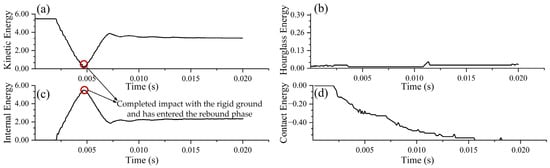
Figure 13.
Energy summary of the package on face A. (a) Kinetic energy curve of face A drop; (b) hourglass energy curve of face A drop; (c) internal energy curve of face A drop; (d) contact energy curve of face A drop.
3.2.2. Verification of Face B Drop Results
The momentum curve for the face B drop of the packaging structure is shown in Figure 14. The energy evolution is broadly similar to that of the face A drop, with the difference that the drop direction here aligns with the positive Z-axis of the software’s built-in coordinate system. As seen in the figure, because the drop direction is along the positive Z-axis, the package’s momentum and impulse in the X and Y directions are both zero. The initial momentum of the package is positive; as the package falls, the magnitude of the momentum gradually decreases, while the impulse begins to increase. When the momentum curve crosses zero on the vertical axis and then increases in the negative Z direction, it indicates that the package has completed impact with the rigid ground and has entered the rebound phase.
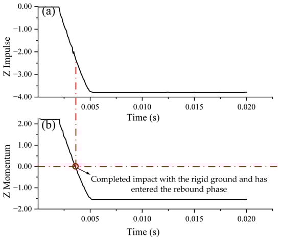
Figure 14.
Momentum summary of the package on face B (The red dashed lines in the figure are auxiliary positioning lines). (a) Impulse curve of face B drop; (b) momentum curve of face B drop.
The energy curve for the face B drop is shown in Figure 15. As shown in the figure, the energy evolution is similar to that of the face A drop. During the drop, the internal energy and kinetic energy curves remain unchanged at the beginning; subsequently, internal energy rises while kinetic energy decreases; finally, during rebound, internal energy decreases and kinetic energy increases. The two curves exhibit symmetric trends, consistent with the theoretical analysis of energy changes during the package drop. For the face B drop, the ratio of hourglass energy to internal energy is 1.190%, meeting the reliability requirement.
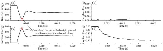
Figure 15.
Energy summary of the package on face B. (a) Kinetic energy curve of face B drop; (b) hourglass energy curve of face B drop; (c) internal energy curve of face B drop; (d) contact energy curve of face B drop.
4. Discussion
4.1. Comparison of Packaging Protective Performance Between HL-1029 Silicone Gel and Other Materials
The current literature predominantly focuses on pouch batteries, which utilize flexible aluminum plastic films. In contrast, the cylindrical lithium-ion batteries used in this study employ rigid steel casings. Due to these fundamental differences in structural mechanics, a direct performance comparison with pouch batteries packaging is not applicable. To rigorously evaluate the effectiveness of the proposed packaging structure, we adopted a mechanics-based safety criterion: the ratio of the maximum stress on the battery to its yield stress .
where is the ratio of the maximum stress on the battery to its yield stress; is the maximum stress on the battery (MPa); is the yield stress on the battery (MPa).
This dimensionless ratio serves as a quantitative indicator to evaluate the cushioning performance of different packaging structures. Specifically, we compared the cushioning performance of the HL-1029 silicone gel used in this study with that of EPE (expanded polyethylene) and all corrugated cardboard materials, as shown in Table 4.
Table 4.
Cushioning performance comparison of different packaging structures and materials.
As indicated by the data in the table above, the ratio of the maximum stress to the yield strength for the lithium-ion battery packaging structure in this paper is 0.033, which is lower than that of the other two structures and materials. Furthermore, the HL-1029 silicone gel exhibits superior sealing and waterproofing performance compared to both EPE and corrugated cardboard. In summary, the lithium-ion battery packaging method designed in this study demonstrates an optimal overall performance.
4.2. Application Prospects and Development Outlook of Green Packaging
4.2.1. Expansion of Application Areas
The green packaging approach that combines HL-1029 silicone gel with corrugated cardboard thanks to its strong sealing, cushioning, protective performance, and recyclability is suitable not only for the 18650 lithium-ion battery studied here but can be extended to other battery formats and to precision electronic components. Products such as laptop batteries, drone power packs, and portable power banks face humidity and impact risks during transport; by adjusting the thickness of the HL-1029 encapsulant and the specifications of the corrugated boxes, the packaging can be adapted to protect different battery types. In the new-energy vehicle sector, the transport and recycling of end-of-life power batteries demand high levels of safety and environmental protection. The combination of HL-1029’s high temperature resistance and leak-prevention properties with the lightweight advantage of corrugated cardboard can reduce the risk of thermal runaway during transport while lowering the burden of packaging waste on the environment. Moreover, for precision electronic components in medical devices or sensitive industrial sensors that require strict sealing and cushioning, this green packaging solution can provide an effective alternative where conventional packaging is inadequate.
4.2.2. Technical Refinement Directions
The current green packaging design already demonstrates robust protective performance, but it can be further optimized in follow-up work. On the materials side, nano reinforcements or flame retardants can be incorporated into HL-1029 silicone gel to improve mechanical strength and thermal stability, ensuring protective performance under extreme conditions. Composite modification with biodegradable additives may also be explored to shorten environmental degradation cycles and enhance life cycle sustainability. From a structural standpoint, parametric modeling driven by vibration and impact data from multiple transport scenarios can be used to optimize the internal cavity geometry of the silicone gel encapsulant, achieving precise matching between cushioning performance and material usage and advancing lightweight design. In addition, future work will focus on the experimental validation of the lithium-ion battery packaging structure designed in this study. Physical drop tests utilizing a drop tester and accelerometers will be conducted to further cross validate the simulation results.
5. Conclusions
The study analyzes the cushioning performance of the proposed green packaging for lithium-ion batteries and draws the following conclusions:
- (1)
- A packaging scheme is proposed in which the battery is fully encapsulated with HL-1029 silicone gel as the inner packaging and housed in a corrugated carton as the outer packaging. This structure not only provides physical protection but also offers superior sealing against humidity and allows for visual inspection, while both materials are fully recyclable.
- (2)
- The drop simulation at 1200 mm height was conducted. Mesh independence verification confirmed that the mesh from 3.00 mm to 2.50 mm percentage change in peak stress of less than 5%. Furthermore, reliability verification based on the energy method showed that the hourglass energy to internal energy ratio was well below the 10% threshold (0.700% for face A; 1.190% for face B), ensuring the accuracy of the numerical results.
- (3)
- The ratio of maximum stress to yield stress for the lithium-ion battery packaging structure in this paper is 0.033, which is lower than that of both the EPE and all corrugated cardboard structures, demonstrating the optimal protective performance for the lithium-ion battery.
- (4)
- Combined with the current state of precision electronic transport packaging, we have expanded the application scenarios for the green packaging structure proposed in this paper. Furthermore, drawing on research from other fields, we have proposed cross-disciplinary optimization directions and explicitly clarified the future research directions of this study.
Author Contributions
Conceptualization, C.L. and J.Z.; methodology, C.L.; software, C.L. and J.Z.; validation, C.L., X.Z. and S.D.; formal analysis, C.L.; investigation, X.Z. and S.D.; resources, P.Z.; data curation, C.L.; writing—original draft preparation, C.L. and J.Z.; writing—review and editing, C.L.; visualization, C.L.; supervision, P.Z.; project administration, P.Z.; funding acquisition, X.Z. All authors have read and agreed to the published version of the manuscript.
Funding
This research was funded by the Fundamental Research Funds for the Central Universities, grant number CUSF-DH-T-2023067.
Data Availability Statement
The original contributions presented in this study are included in the article. Further inquiries can be directed to the corresponding author.
Conflicts of Interest
The authors declare no conflicts of interest relevant to this article.
References
- Besch, K.M.; Palsson, H. A Supply Chain Perspective on Green Packaging Development-Theory Versus Practice. Packag. Technol. Sci. 2016, 29, 45–63. [Google Scholar] [CrossRef]
- Meng, D.; Weng, J.W.; Wang, J. Experimental Investigation on Thermal Runaway of Lithium-Ion Batteries under Low Pressure and Low Temperature. Batteries 2024, 10, 243. [Google Scholar] [CrossRef]
- Liu, J.; Chen, C.; Wen, J.; Chang, Z.; Notten, P.H.; Wei, Y. Size effect on the thermal and mechanical performance of cylindrical lithium-ion batteries. Appl. Energy 2024, 375, 124056. [Google Scholar] [CrossRef]
- Hsueh, T.H.; Wang, M.C.; Liu, S.E.; Wu, B.-H.; Li, Y.-C.; Tsai, D.-G.; Chang, S.-M.; Shiue, A.; Chin, K.-Y. Sputtered silver on the current collector for anode-less NMC111 gel polymer electrolyte lithium batteries. Electrochem. Commun. 2023, 150, 107478. [Google Scholar] [CrossRef]
- Zhou, X.; Wang, Z.; Sun, B.; Zhang, W.; Zhang, C.; Huang, Q.; Wang, S.; Yang, X.; Gong, H. Study of lithium-ion battery module external short circuit risk and protection design. J. Energy Storage 2024, 86, 111070. [Google Scholar] [CrossRef]
- Guo, M.; Yang, H.; Ma, L. Design and analysis of 2D double-U auxetic honeycombs. Thin-Walled Struct. 2020, 155, 106915. [Google Scholar] [CrossRef]
- Gao, Q.; Liao, W.; Wang, L. On the low-velocity impact responses of auxetic double arrowed honeycomb. Aerosp. Sci. Technol. 2020, 98, 105698. [Google Scholar] [CrossRef]
- Su, D.; Liu, Z.; Zhong, H.; Tang, J.; Zeng, F. Research on the improvement and regulation mechanism of silicone gel encapsulation insulation performance for high-voltage power devices. Polym. Degrad. Stab. 2025, 241, 111599. [Google Scholar] [CrossRef]
- He, J.; Xu, P.; Xing, J.; Yao, S.; Wang, B.; Zheng, X. The crashworthiness prediction and deformation constraint optimization of shrink energy-absorbing structures based on deep learning architecture. Adv. Eng. Softw. 2024, 196, 103719. [Google Scholar] [CrossRef]
- Li, R.; Zhao, Z.; Bao, H.; Pan, Y.; Wang, G.; Liu, B.; Liao, T.; Li, J. Bio-inspired honeycomb structures to improve the crashworthiness of a battery-pack system. Eng. Fail. Anal. 2024, 158, 108041. [Google Scholar] [CrossRef]
- Du, F.; Jin, Z.; Yang, R.; Hao, M.; Wang, J.; Xu, G.; Zuo, W.; Geng, Z.; Pan, H.; Li, T.; et al. Thermally insulating and fire-retardant bio-mimic structural composites with a negative Poisson’s ratio for battery protection. Carbon Energy 2023, 5, e353. [Google Scholar] [CrossRef]
- Stephenson, A.M.B.; Puji, S.S.; Djarot, W. Design and optimization of lithium-ion battery protector with auxetic honeycomb for in-plane impact using machine learning method. Front. Energy Res. 2023, 11, 1114263. [Google Scholar] [CrossRef]
- Yang, C.B.; Sunderlin, N.; Wang, W.; Churchill, C.; Keyser, M. Compressible Battery Foams to Prevent Cascading Thermal Runaway in Li-Ion Pouch Batteries. J. Power Sources 2022, 541, 231666. [Google Scholar] [CrossRef]
- Liu, Q.; Zhu, Q.; Zhu, W.; Yi, X. Study on the Blocking Effect of Aerogel Felt Thickness on Thermal Runaway Propagation of Lithium-Ion Batteries. Fire Technol. 2022, 59, 381–399. [Google Scholar] [CrossRef]
- Wu, F.; Chen, N.; Chen, R.; Zhu, Q.; Tan, G.; Li, L. Self-Regulative Nanogelator Solid Electrolyte: A New Option to Improve the Safety of Lithium Battery. Adv. Sci. 2016, 3, 1500306. [Google Scholar] [CrossRef]
- Benson, J.J.; Sakkos, J.K.; Radian, A.; Wackett, L.P.; Aksan, A. Enhanced biodegradation of atrazine by bacteria encapsulated in organically modified silica gels. J. Colloid Interface Sci. 2018, 510, 57–68. [Google Scholar] [CrossRef]
- Zhang, Z.; Zhao, S.; Li, K.F.; Fei, Z.; Chen, G.; Zhang, P.; Yang, Z. Hydrophobic and elastic silica-based aerogels with organic and inorganic in-situ hybrid structure for cryogenic insulation. Mater. Lett. 2023, 338, 134048. [Google Scholar] [CrossRef]
- Soumyoraj, M.; Debabrata, G. Thermal behaviour and thermal runaway propagation in lithium-ion battery systems—A critical review. J. Energy Storage 2023, 62, 106894. [Google Scholar] [CrossRef]
- Tran, M.-K.; Mevawalla, A.; Aziz, A.; Panchal, S.; Xie, Y.; Fowler, M. A Review of Lithium-Ion Battery Thermal Runaway Modeling and Diagnosis Approaches. Processes 2022, 10, 1192. [Google Scholar] [CrossRef]
- Finegan, D.P.; Darcy, E.; Keyser, M.; Tjaden, B.; Heenan, T.M.M.; Jervis, R.; Bailey, J.J.; Vo, N.T.; Magdysyuk, O.V.; Drakopoulos, M.; et al. Identifying the cause of rupture of Li-Ion batteries during thermal runaway. Adv. Sci. 2018, 5, 1700369. [Google Scholar] [CrossRef]
- GB/T 6543-2008; Single Corrugated Boxes and Double Corrugated Boxes for Transport Packages. Standards Press of China: Beijing, China, 2008.
- Brandenburg, R.K.; Lee, J.J.L. Fundamentals of Packaging Dynamics, 4th ed.; L.A.B. Equipment, Inc.: Skaneateles, NY, USA, 2001; pp. 80–120. [Google Scholar]
- Elzohry, A.M.; Khorshed, L.A.; Attia, A.; Adly, M.A.; Mohamed, L.Z. Chemical, Electrochemical and Corrosive Wear Behavior of Nickel-plated Steel and Brass-plated Steel Based Coins from Egypt in Artificial Sweat. Int. J. Electrochem. Sci. 2021, 16, 1–16. [Google Scholar] [CrossRef]
- Liu, F.; Yu, K.; Peng, P. Simulation Experimental Study on Tensile Properties of Nickel-plated Steel Strip with punching. J. Funct. Mater. 2017, 48, 11108–11112. [Google Scholar] [CrossRef]
- Ong, T.C.; Sarvghad, M.; Lippiatt, K.; Bell, S.; Will, G.; Steinberg, T.A. Investigation of the corrosion of electro-less nickel-plated alloys in molten salt and its effect on phase change properties for energy storage applications. Sol. Energy 2022, 236, 512–521. [Google Scholar] [CrossRef]
- Cao, B.F.; Li, J.Q.; Liu, C.F.; Qin, L. Defect detection of nickel plated punched steel strip based on improved least square method. Optik 2020, 206, 164331. [Google Scholar] [CrossRef]
- Gutiérrez, M.I.J.; Sierra, S.M.G.; Ramírez, C.A.G. Effect of electrodeposition parameters and surface pretreatment on the electrochemical hydrogen production using nickel-plated stainless steel electrodes. Int. J. Hydrogen Energy 2021, 46, 7667–7675. [Google Scholar] [CrossRef]
- Mooney, M. A theory of large elastic deformation. J. Appl. Phys. 1940, 11, 582–592. [Google Scholar] [CrossRef]
- ASTM D5276; Standard Test Method for Drop Test of Loaded Containers by Free Fall. ASTM International: West Conshohocken, PA, USA, 2019.
Disclaimer/Publisher’s Note: The statements, opinions and data contained in all publications are solely those of the individual author(s) and contributor(s) and not of MDPI and/or the editor(s). MDPI and/or the editor(s) disclaim responsibility for any injury to people or property resulting from any ideas, methods, instructions or products referred to in the content. |
© 2025 by the authors. Licensee MDPI, Basel, Switzerland. This article is an open access article distributed under the terms and conditions of the Creative Commons Attribution (CC BY) license.