Abstract
Rock burst is one of the most typical dynamic disasters in the process of coal mining. Energy-absorbing components are key to anti-impact equipment. Exploring the mutual feedback relationship between energy-absorbing components and columns for the prevention and control of roadway rock burst is of great significance. In this study, an arc-shaped energy-absorbing component was designed, and its energy-absorbing characteristics were analyzed. The finite element analysis results of the arc-shaped energy-absorbing component were verified via the crushing test machine. The energy-absorption effect of pre-folded, diameter-expanded, eversion, and arc energy-absorbing columns under impact is compared horizontally. The results show that the supporting force is stable during the crushing deformation of the arc-shaped energy-absorbing component, and the average supporting force measured in the test is 1145.35 kN. Compared with the other three energy-absorbing columns, the arc-shaped energy-absorbing column has a lower emulsion pressure peak and the maximum pressure fluctuation amplitude during the impact process; it also has a better deceleration effect on the quality mass. During the impact process, the influence of the arc-shaped energy-absorbing component on the liquid impact in the column is summarized into three stages, namely approximate elasticity, flexible yield energy-absorbing, and approximate rigidity, which can achieve the peak clipping effect on the liquid impact and improve the impact resistance of the column.
1. Introduction
Rock burst is a dynamic disaster caused by the sudden release of energy from high-stress coal rock during coal mining [1,2,3,4,5]. Rock burst incidents have been reported in mines and tunnels globally, including in South Africa, China, Chile, the US, Canada, Western Australia, and many other countries [6,7]. Understanding the mechanical behavior of rock materials under dynamic loading conditions is essential for addressing the challenges associated with underground excavations, rock bursts, and protective structure designs [8]. It has been reported that more than 90% of rock bursts occur on roadways [6,7,8]. Conventional support equipment is often damaged due to the impact of overloading [8]. The roadway anti-impact hydraulic support with energy-absorbing components is a key piece of equipment used to improve the safety of mine operations, maintain the stability of roadways, and protect personnel and equipment from rock burst damage. Therefore, exploring the coupling relationship between energy-absorbing components and columns in the impact process is of great significance to prevent and control roadway rock bursts.
Pan et al. [9,10,11] studied the roadway support theory of rock burst mines, proposed six principles of anti-impact support design, developed a roadway hydraulic support with fast displacement and energy-absorbing function, and achieved good anti-absorbing effects. After the addition of energy-absorbing components, the hydraulic support has a significant impact on the anti-impact effect of roadways. Therefore, relevant scholars have studied the energy-absorbing characteristics of energy-absorbing components used with different structures. To improve the service life of hydraulic support structures under impact loading, Xiao [12] et al. designed an aluminum foam-filled multi-cell square tube and investigated it as an energy-absorption component to prevent support column failure.
The energy-absorption performance of a multi-cell square tube during buckling deformation was investigated via simulation and quasi-static compression tests considering the cross-sectional shape and aluminum foam filling rate. Dai [13] et al. designed an axial splitting energy absorber for rock bolts, explored the mechanical behavior of energy-absorbing components with different parameters, and optimized the structural parameters. The splitting process of the optimized energy-absorbing component is more stable. Sharifzadeh [14] et al. reviewed the evolution of energy-absorbing rock bolts and dynamic test methods, conducted quantitative analysis of their dynamic performance, and proposed a categorization and rating scheme of energy-absorbing rock bolts. Baroutaji [15] et al. investigated the energy-absorption characteristics of sandwich tubes under lateral loading and determined the optimal structural parameters of the energy-absorbing component using a multi-objective optimization method. Pirmohammad [16] et al. evaluated new multi-cell devices in terms of their crashworthiness capability under quasi-static axial and oblique loading; they found that the bitubal multi-cell member with a circular cross-section was the best energy-absorbing device. P.K. Gupta [17] et al. analyzed the deformation behavior of thin-walled aluminum shells with a dome-cone combined geometry; they studied collapse modes with the development of plastic zones and associated energy-absorption capacity. Abbasi [18] et al. characterized the collapse behavior of square, hexagonal, octagonal, and a newly introduced 12-edge section for stable collapse with a high energy-absorption capacity. Multi-objective optimization with the target of maximizing both specific energy-absorption and crush force efficiency was performed using nonlinear finite element analysis via LS-DYNA. Qiao [19] et al. performed experiments under static axial loading conditions for square thin-walled tubes with different thicknesses and section dimensions that were subjected to various impact velocities. The crush behavior of this structure under axial static and dynamic loads was studied, and good agreement was shown between the experiments and numerical model.
The aforementioned scholars have laid a solid foundation for the structural design and optimization of energy-absorbing components; however, the following issues remain to be addressed: (1) The existing energy-absorbing components used in mining have not yet achieved a relatively stable supporting force during impact. Therefore, it is necessary to develop a new type of energy-absorbing component that can provide smooth yielding resistance during impact. (2) At present, in the design process of energy-absorbing components for hydraulic supports in roadways, the focus is mostly on the energy-absorbing characteristics of the components themselves, while their effectiveness under the coupling action with the column has rarely been verified. Therefore, the coupling effect between the energy-absorbing component and the column needs to be analyzed. (3) Furthermore, the issues related to fluid impact on the support after adding energy-absorbing components have not yet received research attention. Therefore, it is crucial to analyze the problems of fluid impact during the impact process.
Aiming to solve the above three problems, this study designs an arc-shaped energy-absorbing component, analyzes its energy-absorbing characteristics during the crushing process, and conducts crushing test verification. Additionally, an impact analysis of several commonly used energy-absorbing columns is conducted, and the energy-absorption effect is compared horizontally. Finally, according to the definite solution conditions of the liquid impact problem of the energy-absorbing column, the influence of the arc-shaped energy-absorbing component on the liquid impact problem of the column under the impact condition is explored.
2. Arc-Shaped Energy-Absorbing Component
2.1. Structural Design of Arc-Shaped Energy-Absorbing Component
In this study, an arc-shaped energy-absorbing component is designed, which adopts an embedded structure with an arc tube as the main tube and a circular tube as the auxiliary, as shown in Figure 1.
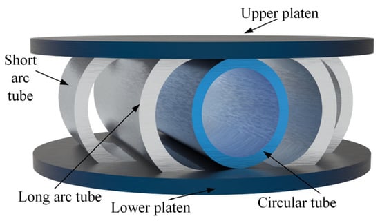
Figure 1.
Structure diagram of arc energy-absorbing component.
The arc-shaped energy-absorbing component is composed of a long-arc tube, a short-arc tube, an upper and lower platen, and a circular tube. In order to facilitate installation in the circular guide sleeve of the energy-absorbing column, the upper and lower platens are designed as a circular platen. The short- and long-arc tubes are fully welded between the upper and lower platen. The outer diameter of the circular tube is equal to the distance between the upper and lower platen and is fixed on the upper and lower platen via spot welding. According to the structural parameters of the 1000 kN column and the guide sleeve, using the peak pressure of the emulsion, the maximum amplitude of the emulsion pressure fluctuation, and the absorbed energy as optimization objectives, a multi-objective optimization method was employed to obtain the parameters of the arc energy-absorbing component: the length of the long-arc tube is 140 mm, the length of the short-arc tube is 70 mm, the length of the circular tube is 140 mm, and the outer diameter of the circular tube is 50 mm. The inner diameters of the long- and short-arc tubes are designed to be equal to the outer diameter of the circular tube, which is 50 mm. The wall thicknesses of the circular tube and the long- and short-arc tubes are 5 mm, 8 mm, and 7 mm, respectively.
2.2. Numerical Simulation of Arc-Shaped Energy-Absorbing Component
In order to evaluate the energy-absorbing characteristics of arc-shaped energy-absorbing components, a finite element model comprising these components is established. The number of arc energy-absorbing structures is set to three, and a finite element simulation of the three groups of different structural parameters is performed. The selected three specific parameter combinations are determined within the feasible region defined by multi-objective optimization and strictly meet the constraints of pillar weight and guide geometry size. These three combinations essentially cover the variation range of thickness parameters with engineering significance under fixed-length conditions (strictly limited by the space of the guide sleeve) and can reflect the typical behavior of the structural response (such as energy absorption, peak pressure, and amplitude). The three groups of structural parameters are shown in Table 1.

Table 1.
Structural parameters of three groups of arc energy-absorbing components.
In the finite element analysis, the mesh size directly affects the accuracy of the results and the speed of the solution [20]. The verification of mesh independence is the key step to ensure the accuracy and reliability of the numerical simulation results. Checking the simulation results under different mesh densities ensures that the numerical solution is stable after mesh refinement to verify the accuracy and stability of the solution. Figure 2 shows the analysis results of arc-shaped energy-absorbing components under different grid sizes.
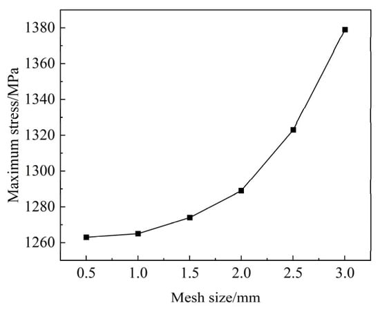
Figure 2.
The influence of mesh size on the results of arc-shaped energy-absorbing components.
As can be seen from Figure 2, as the mesh size decreases, the maximum stress of the arc-shaped energy-absorbing component also decreases. When the mesh size decreases from 3 mm to 1.5 mm, the maximum stress decreases greatly. When the mesh size decreases from 1.5 mm to 0.5 mm, the maximum stress decreases slightly. Considering the solution speed and solution accuracy, the mesh size of the arc-shaped energy-absorbing component is set to 1.5 mm in this study. The key parameters and settings of the finite element analysis are as follows:
- (1)
- Material assignment: The material of the parts is set to 4340 steel, and the Johnson–Cook material constitutive model is used.
- (2)
- Meshing: All meshing methods are set to MultiZone, and the mesh size is set to 1.5 mm.
- (3)
- Contact setting: The contact between the arc tube and the upper and lower platen is set as binding, the rest of the contact is set as friction, the static friction coefficient is set to 0.15, and the dynamic friction coefficient is set to 0.14.
- (4)
- Boundary condition setting: The lower platen is fixed, and all degrees of freedom of the upper platen are limited except for the movement of the Y-axis. The crushing speed is set to 5 m/s.
The simulation time is set to 0.016 s, and the crushing displacement is 80 mm. The finite element simulation results are shown in Figure 3.
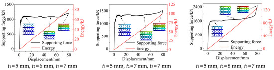
Figure 3.
Numerical simulation results of arc-shaped energy-absorbing components.
As can be seen from Figure 3, with the increase in crushing displacement, the circular tube forms a stable six-hinge deformation mode, and the four plastic hinges in contact with the upper and lower platen are moving hinges, which gradually move outward with the increase in crushing displacement. Under the action of axial crushing displacement, the arc tube forms a three-hinge deformation mode, in which the plastic hinge position of the arc tube in contact with the upper and lower platen is fixed, and the intermediate plastic hinge is not concentrated at a certain point, but with the change in crushing displacement, the position changes only a little in a certain area, which can allow for a more stable supporting force–displacement curve to be achieved. Taking the simulation results of t1 = 5 mm, t2 = 8 mm, and t3 = 7 mm as an example, in the early crushing stage, the supporting force of the energy-absorbing component rises rapidly until it reaches about 1400 kN and the energy-absorbing component is in the elastic deformation stage. With the further increase in the crushing displacement, the energy-absorbing component enters the plastic deformation stage, and the supporting force at this stage rises to about 1600 kN and basically remains unchanged. The crushing displacement increases to about 25 mm, and the supporting force shows a slight upward trend until the crushing displacement reaches about 77 mm. Subsequently, the energy-absorbing component enters the densification stage, and the supporting force rises rapidly.
The above three groups of supporting force–displacement curves show a steady or rising trend. The average supporting forces are 1194.12 kN, 1325.94 kN, and 1573.88 kN, respectively, but there is a small fluctuation. The main reason for the fluctuation is that the deformation mode of the energy-absorbing component runs from top to bottom. In the process of forming the plastic hinge, the force arm gradually increases. Under the condition that the material and structural parameters of the energy-absorbing component remain unchanged, the ultimate bending moment required to form the plastic hinge remains unchanged. Therefore, the increase in the force arm leads to a slight decrease in the supporting force, but the overall supporting force shows a steady or rising trend, which can provide a stable supporting force. Additionally, the energy absorption and displacement of the energy-absorbing components of the above three groups of structural parameters are almost linear, which proves that the energy-absorption process is relatively stable.
2.3. Experimental Verification
2.3.1. Processing and Production of Energy-Absorbing Components
The processing of arc-shaped energy-absorbing components is mainly divided into three parts: long- and short-arc tube processing, upper and lower platen processing, and welding. First, the seamless circular tube is cut to the specified length, and then the circular tube is cut in half to obtain a long-arc tube and a short-arc tube. Then, the upper and lower platen are slotted using wire cutting technology to facilitate the installation of arc tubes. Finally, the parts are welded, the welding method used is full welding, and the parts are heated before welding, which is beneficial to reduce the maximum hardness of the heat-affected zone of the steel, prevent cold cracks, and reduce the residual stress after welding. After welding, the components are subjected to heat treatment using the annealing method. At the same time, the groove treatment is performed at the welding position to reduce the proportion of the base metal melting into the weld metal, reduce the carbon content in the weld, and prevent the energy-absorbing component from cracking during the crushing process. The material for making arc-shaped energy-absorbing components is HG785D steel. The material parameters are shown in Table 2, and the arc-shaped energy-absorbing components are shown in Figure 4.
Table 2.
Material parameters of arc-shaped energy-absorbing components.
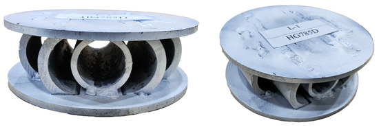
Figure 4.
Physical diagram of arc-shaped energy-absorbing component.
2.3.2. Test Equipment and Scheme
A 5000 kN quasi-static pressure testing machine and a force–displacement sensor acquisition system were used to conduct crushing experiments on arc-shaped energy-absorbing components. The test platform includes a control system, a data acquisition system, a quasi-static pressure testing machine, energy-absorbing component, support seat, and an indenter, as shown in Figure 5.
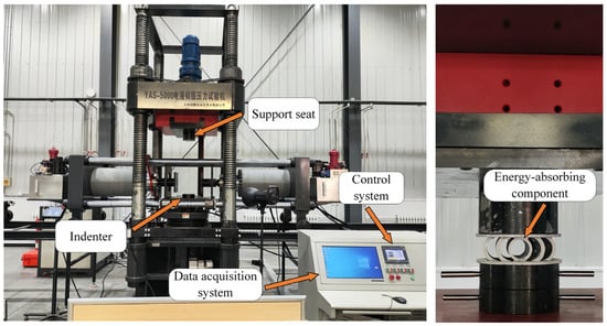
Figure 5.
A 5000 kN electro-hydraulic servo pressure testing machine.
The energy-absorbing component is adjusted to the center of the indenter, and the support seat is lowered to the upper surface of the energy-absorbing component. The crushing speed is set to 3 mm/min, the crushing displacement is set to 25 mm, and the data sampling frequency is set to 10. The test machine starts the crushing test. During the test, the energy-absorbing component did not tilt. The crushing test process is shown in Figure 6.
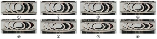
Figure 6.
Crushing test process diagram of energy-absorbing component.
In the axial crushing process of the energy-absorbing component, the deformation mode of the arc tube is almost consistent with the numerical simulation results, showing a stable three-hinge deformation mode. The deformation of the circular tube is slightly different from the numerical simulation results; in particular, the part of the contact between the tube and the upper platen does not form a moving hinge. The main reason for this is that the circular tube is fixed to the inner surface of the upper and lower platen via spot welding, which is different from the free placement of the circular tube in the numerical simulation. The increase in the welding spot affects the deformation mode of the circular tube.
2.3.3. Test Results and Analysis
The data acquisition system is used to synchronously record the supporting force and displacement data of the energy-absorbing component during the crushing process to obtain the supporting force–displacement curve of the arc-shaped energy-absorbing component. In order to verify the accuracy of the numerical simulation, the energy-absorbing components of the same structure were numerically simulated. The crushing speed was set to 2 m/s, and the crushing displacement was 25 mm. A comparison between the test results and the numerical simulation results is shown in Figure 7.
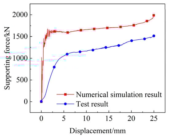
Figure 7.
Comparison of test results and numerical simulation results.
Figure 7 shows that the deformation process of the energy-absorbing component is divided into three stages: First, the energy-absorbing component subjected to axial pressure enters the elastic deformation stage and quickly reaches the starting threshold; then, it enters the plastic deformation stage, where the supporting force is stable and rises slightly, and it absorbs a lot of energy. Finally, the energy-absorbing component enters the densification stage, and the supporting force increases rapidly. When comparing the numerical simulation and test results, the main difference is that there is a certain deviation between the two values. This is because the material used in the test is inconsistent with the numerical simulation material. The yield strength of 4340 steel can reach 835 MPa, and the processing and welding of the specimen also affect the value of the supporting force. In addition, the fluctuation amplitude of the two curves in the initial stage is different. The reason for this phenomenon is that the experimental values are measured under quasi-static conditions, and the crushing speed of the numerical simulation is 2 m/s, which belongs to the dynamic load impact range. Therefore, the numerical simulation results fluctuate. It is worth noting that the trend of the supporting force of the two is very similar, and the supporting force shows a good trend of a steady rise with an increase in the crushing displacement, which helps to protect the column during the impact process.
3. Comparison of Energy-Absorbing Components
3.1. Construction of Finite Element Model of Energy-Absorbing Column
In the absence of energy-absorbing components, the emulsion pressure will surge during the impact of heavy objects on the column, and because there is no buffer of flexible energy-absorbing components, the cylinder and the base of the bracket will have a rigid impact phenomenon, which will further aggravate the damage of the column. After adding flexible energy-absorbing components, the energy of the impact process will be absorbed by the energy-absorbing components, thereby alleviating the phenomenon of a rapid increase in emulsion pressure and avoiding column damage. The impact crushing numerical simulation was performed on the energy-absorbing columns installed with pre-folded (b) [21], diameter-expanded (c) [22], eversion (d) [23], and arc-shaped energy-absorbing components (e). Among them, the energy-absorbing columns installed by the four energy-absorbing components were the same. The finite element model of the energy-absorbing column under the impact of quality mass and the four energy-absorbing components installed is shown in Figure 8.
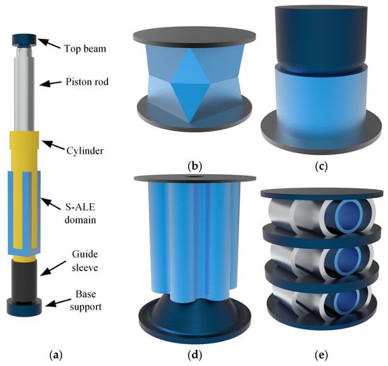
Figure 8.
Finite element models of energy-absorbing column and four energy-absorbing components. (a) Energy-absorbing column; (b) Pre-folded; (c) Diameter-expanded; (d) Eversion; (e) Arc-shaped.
The impact of coal or rock on the column is simulated using quality mass. As can be seen in Figure 8, the finite element model of the energy-absorbing column under the impact of quality mass is composed of the top beam of the column, the piston rod, the cylinder, the guide sleeve, the base support, the energy-absorbing components in the guide sleeve, and the emulsion in the cylinder.
In order to objectively evaluate the influence of each energy-absorbing component on the impact resistance of the column and the movement of quality mass, the parameter settings of the numerical simulation are consistent. The S-ALE (Structure–Arbitrary–Lagrangian–Eulerian) fluid–solid coupling method is used to calculate the emulsion and structural components. The key steps and parameter settings are as follows:
- (1)
- Material assignment: The four kinds of energy-absorbing component materials are set to 4340 steel. The Johnson–Cook material constitutive model is used. The S-ALE domain material is set to air, and the liquid material is set to 5% emulsion. The constitutive of air and 5% emulsion is described by * MAT _ NULL, and the parameters are shown in Table 3. EOS-GRUNEISEN is used as the state equation, and its parameters are shown in Table 4.
- (2)
- Meshing: The meshing method of the four energy-absorbing components is set to MultiZone, and the mesh size is set to 1.5 mm. The S-ALE domain is established on the periphery of the emulsion, as shown in the blue area in Figure 8a; the meshing method is set to S-ALE, and the mesh size is set to 10 mm. The mesh size of the emulsion is set to 10 mm. The mesh size of the cylinder and the piston rod in contact with the emulsion is also set to 10 mm. The mesh size of the quality mass is set to 30 mm, and the mesh size of the remaining components is set to 15 mm.
- (3)
- Contact setting: The static friction coefficient between the outer surface of the piston and the inner surface of the cylinder is set to 0.1, and the dynamic friction coefficient is set to 0.09; the static friction coefficient between the remaining components is set to 0.15, and the dynamic friction coefficient is set to 0.14. In the fluid–solid coupling setting, the Lagrange body selects the cylinder and the piston rod, the ALE body selects the emulsion and the S-ALE domain, the interaction type is set to ALE Structured FSI, and the coupling direction is set to All Directions.
- (4)
- Boundary condition setting: In the impact process, all the degrees of freedom of the top beam of the column are limited, except for the movement of the Y-axis, and all the degrees of freedom of the base support are limited; that is, they are set to be fixed.
Table 3.
Parameters of 5% emulsion and air in * MAT _ NULL material model.
Table 3.
Parameters of 5% emulsion and air in * MAT _ NULL material model.
| Density/(kg·m−3) | Pressure Cutoff/Gpa | Dynamic Viscosity/(Pa·s) | |
|---|---|---|---|
| 5% emulsion | 1000 | −10 | 0.001 |
| Air | 1.25 | 0 | 0 |
Table 4.
Parameters of Gruneisen equation of state for 5% emulsion and air.
Table 4.
Parameters of Gruneisen equation of state for 5% emulsion and air.
| C/(m·s−1) | S1 | S2 | S3 | ||
|---|---|---|---|---|---|
| 5% emulsion | 1480 | 1.92 | −0.096 | 0 | 0.4 |
| Air | 344 | 0 | 0 | 0 | 1.4 |
The mass block weighs 100,000 kg, and the contact mode between the mass block and the top beam is friction. The gravity of the quality mass is given, and the gravity acceleration is 9.8066 m/s2, ignoring the gravity of the remaining components. The simulation time is set to 0.05 s, and a vertical downward remote force is applied to the top beam of the column. The remote force is set to 814,300 N. The force applied to the energy-absorbing component using the equivalent column under the initial support pressure of 32 MPa increases linearly to 814,300 N within 0.01 s, and then it remains unchanged. The initial velocity of the quality mass is set to 3.284 m/s, and the distance between the quality mass and the top beam is set to 56.48 mm. After calculation, the impact velocity when the quality mass reaches the top beam is about 3.48 m/s, which satisfies the action velocity of 1–10 m/s for the top plate fracture-type impact rock burst.
3.2. Energy-Absorption Effect Comparison
In order to horizontally compare the energy-absorption effects of pre-folded, diameter-expanded, eversion, and arc-shaped energy-absorbing components, the energy-absorption effects of each energy-absorbing component were analyzed by taking the emulsion pressure, supporting force of the column, and velocity of the quality mass as the analysis objects during the impact process.
Figure 9 shows the change trend of emulsion pressure of four kinds of energy-absorbing columns during impact. The trend of emulsion pressure of the four energy-absorbing columns is basically the same in the period of 0–20 ms. The pressure rises steadily to 0.8 times the rated working resistance in the period of 0–10 ms, which is about 30 MPa. In the subsequent 10 ms, the emulsion pressure remains stable. Starting from 20 ms, the pressure change trends of the four energy-absorbing columns are different due to the impact of the quality mass and the supporting force of the energy-absorbing component. The emulsion pressure of the pre-folded energy-absorbing column suddenly increases to about 75 MPa and fluctuates violently. Then, the emulsion pressure decreases, and the fluctuation range also decreases until the end of the impact is reached. The emulsion pressure of the diameter-expanded energy-absorbing column rises rapidly to about 97 MPa within 6 ms and then fluctuates in a sinusoidal shape until 40 ms is reached. The pressure fluctuates disorderly at about 45 MPa until the end of the impact. The emulsion pressure of the eversion energy-absorbing column rises to about 73 MPa and then decreases rapidly to about 32 MPa. From 23 ms, the emulsion pressure shows an overall fluctuating upward trend, and the maximum pressure rises to about 109 MPa after the impact. The emulsion pressure of the arc-shaped energy-absorbing column rises to about 72 MPa, and then the emulsion pressure maintains a small fluctuation, but the center value remains basically unchanged. From 47 ms, the emulsion pressure begins to climb. This is because the arc-shaped energy-absorbing component enters the densification stage, and the supporting force provided increases.
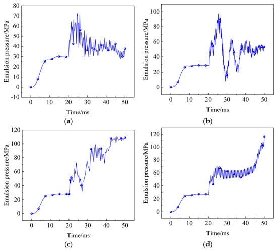
Figure 9.
Emulsion pressure change trend of four kinds of energy-absorbing column. (a) Pre-folded energy-absorbing column; (b) Diameter-expanded energy-absorbing column; (c) Eversion energy-absorbing column; (d) Arc-shaped energy-absorbing column.
Figure 10 shows the changing trends of the supporting force of the four energy-absorbing columns during the impact process. The supporting force of the four energy-absorbing columns is almost the same in the 0–20 ms period. At this stage, the four energy-absorbing components are plastically deformed, and the supporting force of the column is stable at about 800 kN. After the impact began, the supporting force of the four energy-absorbing columns increased rapidly, and the supporting force of the pre-folded, eversion, and arc-shaped columns increased to about 1450 kN, 1460 kN, and 1600 kN, respectively. It is worth noting that the supporting force of the diameter-expanded energy-absorbing column changes greatly in the initial 20–30 ms time range of the impact, which is related to the structure of the diameter-expanded energy-absorbing component. It is pointed out in Reference [24] that with the increase in the crushing speed, the fluctuation range of the supporting force of the diameter-expanded energy-absorbing component also increases. The supporting force of the arc-shaped energy-absorbing column changes smoothly during the impact process, which is almost consistent with the supporting force curve obtained by simulating the arc-shaped energy-absorbing component alone, indicating that the arc-shaped energy-absorbing component can still provide good supporting force in the process of coupling impact with the column.
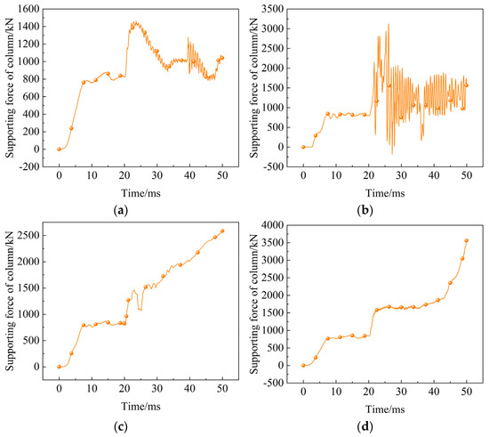
Figure 10.
The changing trends of supporting force of four kinds of energy-absorbing columns. (a) Pre-folded energy-absorbing column; (b) Diameter-expanded energy-absorbing column; (c) Eversion energy-absorbing column; (d) Arc-shaped energy-absorbing column.
Figure 11 shows the changing trends of the velocity of the quality mass during the impact process of the four energy-absorbing columns. The velocity curves of the four kinds of quality mass are almost the same in the period of 0–20 ms, and the quality mass moves freely in this period. From about 20 ms, the quality mass contacts the top beam of the column, and the changing trends of the four kinds of velocity of the quality mass are different. Under the influence of the pre-folded energy-absorbing component, the speed increase trend of the quality mass in the 20–30 ms period is obviously slowed down, but from 30 ms, the velocity continues to increase rapidly. In the control stage of the energy-absorbing component, the velocity of the quality mass increases by 0.21 m/s. This is because the supporting force–displacement curve of the pre-folded energy-absorbing component shows a downward trend as a whole, which leads to a reduction in the energy absorption of the energy-absorbing component under the limited energy-absorption stroke, and the energy released by the impact of the quality mass cannot be effectively absorbed. Therefore, the impact velocity continues to increase. Under the influence of the diameter-expanded energy-absorbing component, the velocity of the quality mass remained stable or even decreased within 20–30 ms, but from 30 ms, the velocity of the quality mass continued to increase. In the control stage of the energy-absorbing component, the velocity of the quality mass increased by 0.1315 m/s, which indicated that the enlarged energy-absorbing column could not make the fractured rock mass stable quickly. The velocity of the quality mass, which benefited from the high reaction force of the eversion energy-absorbing component, remained stable during the period of 20–36 ms under the control of the eversion energy-absorbing component. During the period of 36–50 ms, the velocity of the quality mass showed a downward trend, and the minimum dropped to 3.46 m/s. Under the influence of the arc-shaped energy-absorbing component, the increase in the velocity of the quality mass is significantly reduced. During the regulation of the energy-absorbing component, the velocity of the quality mass is only increased by 0.0315 m/s, indicating that the arc-shaped energy-absorbing component can make the broken rock mass fast and stable, avoiding serious dynamic accidents, which can lead to equipment damage.
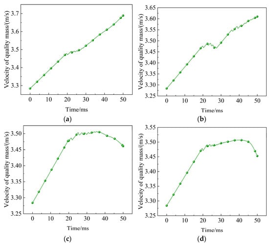
Figure 11.
Changing trend of velocity of the quality mass of four kinds of energy-absorbing columns. (a) Pre-folded energy-absorbing column; (b) Diameter-expanded energy-absorbing column; (c) Eversion energy-absorbing column; (d) Arc-shaped energy-absorbing column.
Table 5 summarizes the performance of four kinds of energy-absorbing columns on the three evaluation indexes of the emulsion pressure peak (Pressuref), emulsion pressure maximum fluctuation amplitude (Pressurea), and extreme value of velocity of the quality mass (Velocitye). The bold font in Table 5 indicates the optimal value of each evaluation index. The Pressuref of the pre-folded energy-absorbing column is the lowest during the impact process, which is 72.54 MPa. This is due to the lower start-up threshold of the pre-folded energy-absorbing component. From the supporting force–displacement curve of the pre-folded energy-absorbing component in Figure 10a, it can be seen that the start-up threshold of the pre-folded energy-absorbing component is about 1450 kN, which is the lowest value among the four energy-absorbing components, indicating that the start-up threshold of the energy-absorbing component significantly affects the Pressuref of the column. The Pressurea and the Velocitye are the lowest, which indicates that the arc-shaped energy-absorbing component and the column have good coupling characteristics during the impact process, which can keep the fluctuation amplitude of the emulsion at a low level, and can quickly and smoothly reduce the velocity of the quality mass to achieve the purpose of giving way to stop the impact.
Table 5.
Evaluation index results of four kinds of energy-absorbing columns.
4. Conclusions
During the yielding and energy absorption process of the anti-impact hydraulic support on the roadway, the influence of the arc-shaped energy-absorbing component on the liquid impact in the column is divided into three stages: approximate elasticity, flexible yielding and energy absorption, and approximate rigidity. The starting threshold of the energy-absorbing component has a significant effect on the peak pressure of the liquid. The results show that the arc-shaped energy-absorbing component has good energy-absorption characteristics with a stable supporting force during the crushing process. At the same time, in this study, several common energy-absorbing components are compared horizontally. The superiority of the arc-shaped energy-absorbing component is also verified from the perspective of the column supporting force, the maximum fluctuation range of the emulsion pressure, and the velocity of the quality mass. The hydraulic column with the arc-shaped energy-absorbing component has an approximate constant resistance yielding characteristic; it can realize the peak clipping effect on liquid impact, and the impact resistance is evidently improved as a result. The conclusions made in this study are based on the performance analysis of core energy-absorbing elements. Subsequent work will involve designing and conducting impact load bench tests on a complete rack to ultimately verify the energy-absorption effect of this design under real working conditions.
Author Contributions
J.D.: Investigation, Resources, Writing—Review and Editing. C.W.: Formal Analysis, Investigation, Writing—Original Draft. J.Z.: Conceptualization, Supervision, Funding Acquisition. All authors have read and agreed to the published version of the manuscript.
Funding
This work was supported by the National Major Scientific Research Instrument Development Project of China—Coal mine rock burst experiment instrument (52427805).
Data Availability Statement
The original contributions presented in this study are included in the article. Further inquiries can be directed to the corresponding author.
Conflicts of Interest
Author Jiaguang Du was employed by Xinjiang Tebian Electric Group Co., Ltd. Author Chuanxu Wan was employed by Intelligent Manufacturing Center, Xinjiang Tianchi Energy Co., Ltd., Subsidiary of Tebian Electric Apparatus. The remaining author declares that the research was conducted in the absence of any commercial or financial relationships that could be construed as a potential conflict of interest.
References
- Pan, J.; Xia, Y.; Wang, S.; Ma, W.; Zhang, C.; Wang, B. Technical difficulties and emerging development directions of deep rock burst prevention in China. J. China Coal Soc. 2024, 49, 1291–1302. [Google Scholar]
- Tan, Y.; Zhang, X.; Xiao, Z.; Fan, D.; Yi, Y.; Chen, Y.; Liu, X. Main control factors of rock burst and its disaster evolution mechanism. J. China Coal Soc. 2024, 49, 367–379. [Google Scholar]
- Liu, H.T.; Chen, Z.H.; Han, Z.; Liu, Q.; Han, Z.; Zhang, C.; Zhang, H. Analysis of dynamic loading events and the risk of roadway rockburst. J. China Coal Soc. 2024, 49, 1771–1785. [Google Scholar]
- Adoko, A.C.; Gokceoglu, C.; Wu, L.; Zuo, Q.J. Knowledge-based and data-driven fuzzy modeling for rockburst prediction. Int. J. Rock Mech. Min. Sci. 2013, 61, 86–95. [Google Scholar] [CrossRef]
- Li, X.L.; Chai, Y.J. Determination of pillar width to improve mining safety in a deep burst-prone coal mine. Saf. Sci. 2019, 113, 244–256. [Google Scholar] [CrossRef]
- Waqar, M.F.; Guo, S.; Qi, S. A comprehensive review of mechanisms, predictive techniques, and control strategies of rockburst. Appl. Sci. 2023, 13, 3950. [Google Scholar] [CrossRef]
- Waqar, M.F.; Guo, S.; Qi, S.; Karim, M.A.; Zada, K.; Ahmed, I.; Shang, Y. Influence of Mineralogical and Petrographic Properties on the Mechanical Behavior of Granitic and Mafic Rocks. Minerals 2025, 15, 747. [Google Scholar] [CrossRef]
- Waqar, M.F.; Qi, S.; Zheng, B.; Guo, S. Dynamic Testing Methods and Failure Properties of Rocks: A Comprehensive Review. Rock Mech. Rock Eng. 2025. [Google Scholar] [CrossRef]
- Dai, L.P.; Pan, Y.S.; Li, Z.H.; Wang, A.; Xiao, Y.; Liu, F.; Shi, T.; Zheng, W. Quantitative mechanism of roadway rockbursts in deep extra-thick coal seams: Theory and case histories. Tunn. Undergr. Space Technol. 2021, 111, 103861. [Google Scholar] [CrossRef]
- Pan, Y.; Xiao, Y.; Luo, H.; Wang, G.; Shi, T. Study on safety of rockburst mine. J. China Coal Soc. 2023, 48, 1846–1860. [Google Scholar]
- Tang, Z.; Pan, Y.; Wang, K. Dynamic analysis of support for surrounding rock of rockburst roadway. Chin. J. Geotech. Eng. 2015, 37, 1532–1538. [Google Scholar]
- Pan, Y.; Xiao, Y.; Li, Z.; Wang, K. Study of tunnel support theory of rockburst in coal mine and its application. J. China Coal Soc. 2014, 39, 222–228. [Google Scholar]
- Pan, Y.; Wang, K.; Xiao, Y. Design of Anti-scour Support Based on Theory of Pendulum-Type Wave. Chin. J. Rock Mech. Eng. 2013, 32, 1537–1543. [Google Scholar]
- Pan, Y.; Xiao, Y.; Li, G. Roadway hydraulic support for rockburst prevention in coal mine and its application. J. China Coal Soc. 2020, 45, 90–99. [Google Scholar]
- Xiao, X.; Li, Z.; Xu, J.; Ding, X.; Fan, Y.; Wu, B. Experimental and numerical study on the energy absorption performance of aluminum foam-filled multi-cell square tubes. Structures 2024, 62, 106250. [Google Scholar] [CrossRef]
- Dai, L.; Xiao, Y.; Pan, Y.; Wang, A.; Fan, C.; Guo, J. Mechanical behavior and factors influencing axial splitting energy absorbers and optimized application for rock bolts. Tunn. Undergr. Space Technol. 2020, 102, 103427. [Google Scholar] [CrossRef]
- Sharifzadeh, M.; Lou, J.; Crompton, B. Dynamic performance of energy-absorbing rockbolts based on laboratory test results. Part I: Evolution, deformation mechanisms, dynamic performance and classification. Tunn. Undergr. Space Technol. 2020, 105, 103510. [Google Scholar] [CrossRef]
- Baroutaji, A.; Gilchrist, M.D.; Smyth, D. Analysis and optimization of sandwich tubes energy absorbers under lateral loading. Int. J. Impact Eng. 2015, 82, 74–88. [Google Scholar] [CrossRef]
- Pirmohammad, S.; Marzdashti, S.E. Crushing behavior of new designed multi-cell members subjected to axial and oblique quasi-static loads. Thin-Walled Struct. 2016, 108, 291–304. [Google Scholar] [CrossRef]
- Gupta, P.K.; Gupta, N.K. A study of development mode of collapse with variation of strains and stresses during compression of metallic shells having dome-cone shape. Thin-Walled Struct. 2018, 126, 68–78. [Google Scholar] [CrossRef]
- Abbasi, M.; Reddy, S.; Ghafari-Nazari, A.; Fard, M. Multiobjective crashworthiness optimization of multi-cornered thin-walled sheet metal members. Thin-Walled Struct. 2015, 89, 31–41. [Google Scholar] [CrossRef]
- Qiao, J.; Chen, J.; Che, H. Crashworthiness assessment of square aluminum extrusions considering the damage evolution. Thin-Walled Struct. 2006, 44, 692–700. [Google Scholar] [CrossRef]
- Yin, X.; Shu, Y.; Liang, L.; Zhang, S. Stability analysis of shield excavation surface in saturated silt strata considering seepage. Rock Soil Mech. 2023, 44, 2005–2016. [Google Scholar]
- Ma, X.; Pan, Y.S.; Xiao, Y.H. Study on Application of the Mine Anti-Impact and Energy-Absorption Device. Appl. Mech. Mater. 2013, 470, 598–603. [Google Scholar] [CrossRef]
Disclaimer/Publisher’s Note: The statements, opinions and data contained in all publications are solely those of the individual author(s) and contributor(s) and not of MDPI and/or the editor(s). MDPI and/or the editor(s) disclaim responsibility for any injury to people or property resulting from any ideas, methods, instructions or products referred to in the content. |
© 2025 by the authors. Licensee MDPI, Basel, Switzerland. This article is an open access article distributed under the terms and conditions of the Creative Commons Attribution (CC BY) license.