Abstract
Usually, biomass combustion in grate-fired boilers presents significant challenges due to the heterogeneous nature of the fuel, chemical composition variability, and complex thermal and chemical conversion processes along the grate. Accurate modeling of the fuel bed conversion is critical for optimizing combustion performance and reducing emissions. However, detailed bed models are often computationally intensive and time-consuming. To address this issue, the present work details a simplified empirical bed model that is integrated into a 3D computational fluid dynamics (CFD) simulation of a 35 MW industrial grate-fired boiler. The model successfully reproduced the flue gas mass flow rate, temperature, and chemical composition across different grate sections, predicting an average furnace outlet temperature of 994 °C, CO mass fraction of 779 mg/m3, CO2 concentration of 12 vol.%, and O2 concentration of 9.5 vol.%. These results fall within the range reported in recent CFD studies of similar systems and are consistent with operational monitoring data from the same plant. Sensitivity analyses showed that modifying the primary-to-secondary-air split ratio from 79/21 to 40/60 reduced the average CO mass fraction at the furnace outlet by more than 50%. Additionally, the average furnace temperature increased up to 1050 °C, enhancing combustion efficiency. The CFD model also demonstrated that relocating char combustion to later grate sections led to temperature imbalances near the boiler walls, emphasizing the importance of grate-specific conversion profiles. These results underscore the model’s ability to guide air distribution optimization, improve combustion performance, and reduce pollutant emissions in biomass boilers.
1. Introduction
Currently, the energy sector is facing strong regulatory pressure, higher competition, and a demand to provide greater flexibility and environmentally friendly solutions. Due to this, currently, it is necessary to respond effectively and rapidly to the fast-changing context of the electricity market. The energy transition is on top of the agenda, and computer-aided methods from the field of computational fluid dynamics (CFD) have been, in part, one of the cornerstones enabling such a paradigm shift. Regarding electricity production using solid biomass, grate firing is currently the most common technology, as well as for the incineration of household residual wastes and household-type commercial wastes [].
Computer-aided methods, over the past few decades, have been the focus of extensive research. In particular, CFD has progressed rapidly and has fundamentally improved the product design process, redesign, and troubleshooting. In the specific case of combustion applications, CFD simulations allow for a deeper analysis of the sub-processes occurring by computing the local velocity, temperature, gas species concentration, and pressure losses, among other parameters [,]. This analysis enhances the knowledge of sub-processes and allows for the design and optimization of boilers, avoiding the trial-and-error approach usually applied by the power plant operators that offers no guarantee of success and is time- and cost-consuming. The outcome of the improved combustion can be lower pollutant emissions, improved efficiency, increased plant capacity, or/and reduced maintenance costs.
However, biomass combustion modeling in an industrial boiler is a very complex process. Suitable models are required because most CFD commercial packages are limited in handling biomass conversion as they are mainly designed to simulate the combustion of gaseous fuels. Thus, in most cases, the commercial software must be complemented by self-written code for fuel bed conversion. In this sense, CFD-based modeling approaches for biomass combustion systems mainly comprise a bed model and a gas-phase simulation.
The fuel bed model should describe the fundamental phenomenon of biomass thermochemical conversion, which will further provide the inlet information for the gas-phase simulation in the freeboard. This model includes aspects such as fuel properties (physical, chemical, and thermal), the biomass conversion process (drying, devolatilization, and char combustion), gas-phase reactions inside the fuel bed, physical changes (shrinking, collapsing, and channeling), and the movement of the particles in the bed model for increased accuracy. Consequently, fuel bed modeling is challenging because solid biomass is a heterogeneous fuel concerning its properties (mainly their chemical composition, moisture, size, and shape). Therefore, there is no general approach that can be used for a biomass type, as well as the combustion system. However, the objective of the simulation has a crucial role in the bed model selection since the products of solid fuel thermo-chemical conversion, which must be predicted by the bed model, will be used as the inlet boundary condition for the gas-phase simulation.
In a recent overview of comprehensive simulations of industrial biomass grate-fired boilers using moving grates [], it was found that the current modeling strategies employed in the literature can be assigned to the following groups: (1) results from experimental measurements defining the boundary conditions to the CFD model [,,], (2) external bed models computing the boundary conditions to the CFD model, and (3) the incorporation of bed models in the CFD model. The external bed model can be classified as empirical (e.g., [,,,,,,,,,,]), which means that it is often based on experienced conversion rates along the grate, or separate (e.g., [,,,,,,,,,,,,,,,]) when there is a mathematical model describing the biomass conversion dependent or not dependent on the freeboard conditions. These models can be classified based on the level of assumptions, starting from zero-dimensional models, which are based on empirical equations [], to two-dimensional models [] and three-dimensional models [,], considering the spatial and temporal dependence of the most important variables. Another method for treating the fuel bed zone is using reactor models to describe the conversion process in different grate zones. Galletti et al. [] and Patronelli et al. [] applied a perfectly stirred reactor model to simulate the bed combustion in small-scale grate-fired boilers, while Matzing et al. [] and Netzer et al. [] used a one-dimensional and a zero-dimensional reactor model to predict the combustion inside industrial-scale grate-fired boilers.
In turn, the inclusion of the bed model can follow two different categories: discrete particle method-based bed models (e.g., [,,,]) or Eulerian/porous medium bed models (e.g., [,,,,,,,,]). In general, this is the most complex approach. Thus, the computational effort of the bed model is a challenging issue when a comprehensive simulation of biomass combustion in grate-fired boilers is required, as a gas-phase simulation already demands significant resources. As a result, the level of detail of the bed model tends to be lower, and empirical or separate bed models are preferred. However, with the rapid development of computer hardware and numerical methods, the level of detail of bed models has increased significantly over the last few years.
Consequently, the inclusion of the bed model into the computational domain of the gas-phase simulation has become more common, allowing for a significant improvement in the description of chemical and physical processes involved in the grate. Nevertheless, even with the progress of hardware resources, a high percentage, around three-quarters, of the literature reviewed used an external bed model to compute the boundary conditions necessary to perform the CFD simulation (e.g., [,,]), and the remaining works used a CFD model with an internal bed model. The reason that leads to the choice of external models is naturally the simplicity and the lower computational cost necessary to carry out the simulations. Furthermore, for instance, Zadravec et al. [] investigated the impact of different results of different bed models. The authors concluded that simplified bed models, like 0D, are still helpful and can be used in CFD for furnace design and optimization since they appropriately account for biomass conversion along the grate. From an engineering point of view, Costa et al. [] also analyzed the suitability of different bed models and stated the same conclusion: that simplified 0D models may be implemented into CFD combustion models as grate inlet boundary conditions.
However, it remains unclear how devolatilization, the main step of biomass combustion and decisive in gas-phase reactions, is addressed by the definition of volatile compound quantities for CFD simulations. Most numerical simulations rely on biomass elemental composition and enthalpy conservation equations, or models such as those proposed by Thunman et al. [] and Neves et al. [], to determine the composition of volatile compounds (e.g., []). Hence, this work presents an effective CFD model for evaluating the nominal operating conditions and the dynamic behavior of combustion on the grate, using a simplified bed model that incorporates volatile compositions experimentally determined through a purpose-built small-scale reactor. The application of the numerical model for further combustion optimization is also the subject of this work.
2. The Grate-Fired Boiler: Case Study
The simulation concerns an existing grate-fired boiler, with approximately 35 MWth and an efficiency of 80%, from a dedicated biomass power plant in Portugal. In this power plant, the received solid biomass is shredded and transported to a reciprocating grate that feeds a vibrating grate. The fuel is highly heterogeneous in terms of composition and dimension and is mainly composed of forest residues from the eucalyptus pruning and harvesting. As moisture and inert content are seasonal parameters, their value is monitored continuously. The reciprocating grate is equipped with a double moving system, and grate girders move up/forward every second while the neighboring grate girders move down/backward and vice-versa. In the vibrating grate, the temporal spacing of vibration cycles and their duration are manually fixed, with typical values of 10 min and 2.5 s, respectively. The grate is inclined at 6° to increase the movement capability and provide a natural cooling water circulation. The construction of these tubes along the grate favors horizontal movement and prohibits the transportation of particles across the tubes []. After the vibrating grate, there is a wet ashtray where the ashes, unburned, and silica agglomerates with a great hardness formed during the biomass combustion process are collected. Regarding biomass feeding, its control is carried out by two controllers: one cargo and another related to the feeding grate velocity. The reference flow rate of solid biomass is 12.2 tons/h for the maximum load and considering a typical moisture of 40%.
The air flow rate for the combustion process is split into primary and secondary and is automatically regulated by the boiler control system. The primary air is provided through the moving and vibrating grate and depends on the moving grate velocity according to an air stoichiometric curve introduced by the manufacturer to adjust the primary air according to the gas emissions. Only a low percentage of the total primary air flow rate is preheated and provided by the moving grate. Hence, a major part of the primary air flow rate is supplied through the vibrating grate, which is divided into three sections with the same dimensions. The first two sections are the ones where more air is provided, being the highest air flow rate reported in the second section. Usually, in the third section, no air or only a small amount of air is supplied. This option is due to the almost complete biomass conversion in the grate’s first sections. In turn, the secondary air system is also controlled based on the grate velocity and the oxygen content in the flue gases measured at the power plant’s chimney. The total secondary air flow rate is divided by 117 nozzles that are 38 mm in diameter and located at different height levels. The main combustion parameters are present in Table 1. More details about the fuel burnt in the power plant and its combustion performance can be found in Silva et al. [,].

Table 1.
Nominal operating conditions of the biomass grate-fired boiler.
3. CFD Simulation Methodology
This chapter presents the mathematical formulation behind a dense particle system to study and analyze the highly multi-scale and interconnected phenomena. The numerical model consists of the utilization of an empirical bed model based on biomass conversion into the different grate sections of the industrial grate-fired boiler, while the CFD analysis is based on the ANSYS Fluent 2020 R1 software. This software is used for fluid flow and heat transfer problems and is structured with numerical algorithms capable of solving them, as well as chemical reactions that occur on the freeboard of the equipment. In the following sections, more details about the two different parts of the numerical model are described.
3.1. Fuel Bed Conversion Model
Combustion in a grate-fired boiler can be considered as a fixed bed of fuel that interacts with the interior of the furnace (freeboard). Thus, it becomes important to determine the mass flow rate of the gases released along the grate, their temperature, and the mass fraction of the different chemical compounds. According to the literature, the biomass combustion process in the bed can be divided into four successive or overlapping subprocesses. Devolatilization, a key stage in gas-phase combustion in the freeboard, typically consists of the emission of volatile compounds such as hydrogen, carbon monoxide, carbon dioxide, and methane, although their composition depends on the fuel type and origin.
In this work, an empirical equilibrium model that describes biomass conversion as a function of grate length is used to obtain the initial boundary conditions for the region above the grate. This methodology has been successfully used in the literature for similar studies to predict a comprehensive conversion behavior of biomass combustion in a fixed bed [,,,,,]. Moreover, its performance and accuracy were comparable to some other models. The empirical equilibrium model adequately addresses this engineering problem and provides a more reasonable correct boundary condition for the CFD modeling [,,,]. Hence, biomass conversion on the grate is exposed to a radiation heat flux from the flame in the upper part of the boiler, and to a primary air flux from beneath the grate. In addition, as the biomass is converted to water vapor, volatiles, carbon monoxide, and carbon dioxide from the char oxidation are released. The operating conditions for each position on the grate are the fuel feeding rate, composition, temperature of the fuel and air, incoming radiation flux, and biomass conversion rate. Taking into account those conditions, an overall mass and energy balance can be established to provide the profiles of temperature, species concentrations, and velocity of the gas leaving the fuel bed into the freeboard. Consequently, the bed model will provide an appropriate lengthwise profile of these parameters along the grate based on the experience and design of the grate-fired boiler.
In this way, the mass flow rate released in each (1, 2, or 3) section of the grate can be computed by Equation (1):
The terms on the right side of Equation (1) represent the mass flow rate of moisture, volatiles, char, and air released. These quantities are obtained, as previously mentioned, based on operational experience with the boiler [] by adapting the percentage of biomass drying, devolatilization, and char oxidation conversion, as well as that of combustion air, across different grate sections. As will be discussed later in Section 4.2, this approach also enables the investigation of how combustion stages evolve along the grate.
In turn, an energy balance represented in Equation (2) is defined to compute the gas temperature:
where the terms , , and represent the radiative heat transfer from the freeboard region to the zone of the grate, latent heat of water evaporation (2250 kJ/kg), and the energy required to start the devolatilization (418 kJ/kg), respectively. The net heat flux received by the fuel bed is assumed to be constant and uniformly distributed in the first two sections of the grate. In the final part of the grate, since most of this section is not exposed to flame radiation, only a minor contribution of the radiation was considered.
and are the heat released from char by complete oxidation and partial oxidation, respectively. Their values are 32,794 kJ/kg and 9208 kJ/kg, respectively. Regarding the last terms, is the reference temperature, the total mass flow rate released in each grate section, and the specific heat of the flue gases.
The char reaction and its products in the fuel bed are assumed to be oxidized and produce either CO or CO2, as expressed in Equation (3). To compute the split ratio between these two chemical compounds, Equation (4) expresses a mathematical relation between their mass fractions and the temperature in the grate.
Consequently, according to Equation (5), the mass flow rates of CO and CO2 from the char reaction in the zone of the grate can be estimated by Equations (5) and (6), respectively.
In addition to the species released during the char conversion, additional quantities of CO, CO2, CH4, and H2 are considered to be released from the fuel bed into the freeboard due to the devolatilization reaction. These quantities are based on isothermal experimental measurements at 800 °C in a small-scale reactor where eucalyptus chips were burnt, and their gaseous emissions were measured using a gas chromatograph. More details about the experiments and the measurements carried out in the small-scale reactor can be found in [,] and at particle scale in [].
O2 is also considered as input to the freeboard, but its amount is related to the remaining fraction after its reaction with the char particles. Furthermore, considering the experience in the biomass power plant, there is a significant amount of unburnt fuel in the ashtray, and it was considered that only 80% of the char reacts []. In turn, the radiation incident on the fuel bed top was based on the results presented in the literature and adapted to the size of the boilers studied in this work [,]. Additionally, as the entire grate is not equally exposed to flame radiation and wall radiation, it was considered that only 10% of heat flux is transmitted to the last section. Regarding the air supply conditions, for the nominal operating conditions, the primary-to-secondary-air ratio is 79/21 and the excess air is 40%. Additionally, the division of the air in the grate as well as the fuel properties considered for the bed model are detailed in [].
3.2. Gas-Phase Combustion Model
Based on the conditions defined by the bed model presented in the previous section, ANSYS Fluent software predicts the gas-phase combustion inside the furnace. This simulation program discretizes the fundamental differential governing equations for mass, momentum, and energy conservation through the finite volume method. For reactive flows such as combustion phenomena, ANSYS Fluent solves additional transport equations for each species involved in the chemical reactions. Apart from solving the fundamental transport equations, there is the need to use other sub-models to describe the fluid flow inside the grate-fired boiler fully. This requires the modeling of turbulence, radiation, and combustion.
The turbulence in this work was modeled through the Reynolds-averaged Navier–Stokes (RANS) equations approach, and using the two-equation model, more specifically the realizable k-ε model. Furthermore, since turbulent flows are significantly affected by the presence of walls, and as the no-slip condition at the walls must be satisfied, the standard wall function, a logarithmic law to compute the mean velocity and temperature, is applied.
Regarding the radiation, at high temperatures, as in combustion that occurs in biomass boilers, it is the dominant heat transfer mechanism from the sidewalls of the boiler to the bed. Hence, radiation is included in the calculation through a source term in the energy equation. The source term, in turn, is determined by the utilization of the discrete ordinates model, while the mixture absorption coefficient is defined through the weighted sum of gray gases model.
To close the mathematical model, the mixing, transport, and reactions of chemical species are modeled using the finite rate–eddy dissipation model and considering a global reaction mechanism. The combustion mechanism is composed of the following three elementary reactions:
The values of the stoichiometric coefficients and reaction exponents, as well as the constants of the various reactions considered in this work to form the combustion mechanism in the gas phase, are presented in Table 2.

Table 2.
Kinetic reaction rate data for the combustion mechanism.
A usual assumption in the gas-phase combustion modeling is that the reactions are kinetically fast just above the fuel bed, where the temperature is typically high in some parts of the grate, and the reactions are fast. Consequently, the combustion is only controlled by the mixing rate of the oxidizer and the volatiles. However, there are areas where the temperature is lower, and the kinetics of gas-phase reactions will become the restricting mechanism. This is why the finite rate model, where the minimum value between kinetics and mixing is the factor that limits the reaction rate, was selected [,]. This model is frequently used together with the eddy dissipation model, which was developed by Magnussen and Hjertager [,] to compute the limiting chemical reaction rate. This model was developed and validated for combustion with strong turbulence. However, as inside industrial boilers, there are some regions with low turbulence: mainly near the bed, the chemical reactions are influenced by the turbulent mixing of the flue gas since, due to the high temperatures, kinetic limitations are less significant []. Therefore, as the bed affects the gas flow, damping the turbulence, some authors modified the Magnussen parameter to account for the effect of the particles over the turbulence and consequently obtain a better turbulence–chemistry interaction [,,,,,,]. In general, with this model, the gas temperatures tend to be over-predicted due to abnormal higher reaction rates, and, consequently, the species concentrations are also often inaccurately estimated []. Considering this issue, the value of , an empirical constant used in the model, was modified to 0.6 for all reactions, taking into account the results presented in the literature [,,,,,,].
An incompressible pressure-based solver is used for CFD simulations. This solver guarantees the mass conservation of the velocity field by solving the pressure equation. Basically, while enforcing mass conservation, the pressure equation is obtained by derivation of the continuity and momentum equations by the pressure. Since the governing equations of the CFD model are non-linear and are interlinked, the solution can only be obtained through an iterative process. To solve these equations sequentially, one after the other, the pressure-implicit with splitting of operators (PISO) algorithm is used in a segregated form. This algorithm was preferred over the semi-implicit method for pressure-linked equations (SIMPLE) to solve the pressure–velocity coupling since it is more efficient, requires a reduced number of iterations to converge, is useful for unsteady flow simulations, and presents better results for meshes with a reduced quality.
For spatial discretization, the convection terms of the different transport equations are solved using first-order upwind methods, except for species transport equations, which are solved using the second-order upwind method. For the gradient terms, to evaluate diffusive fluxes and velocity, the least-squares cell-based method was selected. Both methods for spatial discretization were selected due to their easier convergence and a less computationally intensive simulation. In addition to the previous interpolation schemes, for pressure, PRESTO! was selected due to its suitability for highly swirling flows involving steep pressure gradients.
Furthermore, regarding the transient formulation, the computational model was solved using a first-order implicit method, and the convergence criterion for the iterative calculation was defined as 1 × 10⁻³ for continuity, momentum, and turbulence equations and 1 × 10⁻⁶ for energy and the discrete ordinates equation. An automated method was used to decide the fluid time step according to the convergence rate of the previous step. Nonetheless, the values were limited between 1 × 10⁻⁶ s and 0.01 s, considering a Courant number of 1.
The contribution of the gravitational acceleration was implemented in a downwards direction along the y-axis, with a magnitude of 9.81 m/s2.
The simulations were computed in a twenty-core (logical) processor with 128 GB of memory RAM. The results are time-averaged after the boiler reaches a pseudo-steady state.
3.3. Geometrical Model and Mesh
For the numerical simulations of the reactive gas phase flow in the ANSYS Fluent software, the first step consists of the definition of the computational domain to be studied. The geometric configuration of the boiler presents symmetry since the secondary air jets on the side walls are equally spaced along its width. Thus, it is only necessary to have a 1/13 slice of full width, corresponding to a slice of 320 mm in thickness. This simplification allowed for a significant reduction in the geometry modeling complexity and the subsequent mesh generation. The geometry of the boiler was developed using the scripting language from Gmsh software v.4.11, providing the possibility to automate the generation of the model with a reduced interface for the user and an easy execution of complex geometries. This configuration was based on the technical drawing of the equipment, and Figure 1 presents an overview of the geometrical model. As can be observed in this figure, the grate region in the lower part of the model was divided into three separate zones in the lengthwise x-direction according to the primary air supply. Hence, it allowed for the introduction of different boundary conditions to better reproduce the biomass thermal conversion.
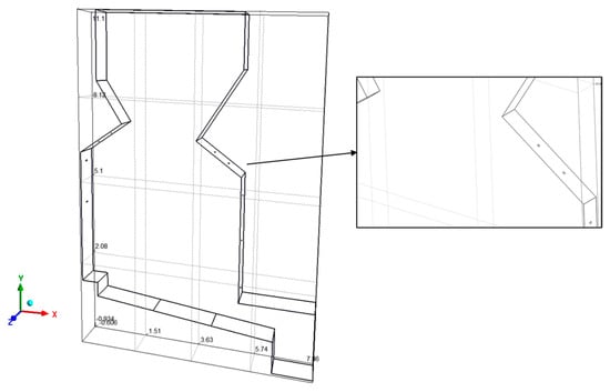
Figure 1.
Representation of the 3D model.
The secondary air is supplied through nine side nozzles located above the grate. Concerning the secondary air injectors, despite making the mesh construction difficult, it was decided to maintain the circular section of 38 mm in diameter. The gases released from the bed will flow upwards and mix with the secondary air to ensure that the combustion of the gases is completed and that they are sent to the outside through the upper face of the model.
Regarding the boundary conditions, the faces corresponding to sections 1, 2, and 3, the outlet (the upper part of the model), and secondary air nozzles were selected. The sidewalls of the model were considered adiabatic, while the front and back faces of the model were defined as having a symmetrical condition so that there was no influence on the fluid flow. The values used for the boundary conditions are based on the nominal operating conditions of the boiler presented in Table 1 and the composition of the main fuels used in the power plant presented in [], along with the results from the empirical bed model. Furthermore, the fluid properties were considered as an incompressible ideal gas.
Time and effort were devoted to developing the numerical mesh as its quality affects the accuracy of the CFD results. This task required much work due to changing the domain division strategy and locations of the refinement in order to change the size of elements in the different zones of the domain. All this work was carried out in order to increase the accuracy and reliability of the results. The OpenFOAM algorithms, in particular, the cartesianMesh option, were used to generate a mesh around hexahedral cells, with refinements in specific zones to obtain a suitable resolution of the temperature and velocity field in regions of strong gradients. Three different meshes were developed to assess the influence of the discretization in the numerical results, with a minimum element size of 10 mm and a maximum of around 100 to 150 mm. The specification of these two parameters resulted in three different meshes with around 250 k, 500 k, and 1M cells. Figure 2 presents an outline of one of the developed meshes with details on specific areas where it is possible to observe the refinement that took place in the central area of the furnace and next to the secondary air injectors. As the quality of the results is highly mesh-dependent, the mesh quality parameters were controlled to obtain a high-quality mesh.
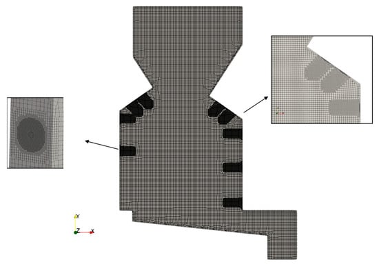
Figure 2.
Overview of the mesh and its details in the region of the secondary nozzles.
Regarding the grid independence analysis, reactive numerical simulations were performed using the different meshes and considering the nominal operating conditions. Temperature and velocity were considered as the variables of interest to assess the differences in the numerical predictions at two specific locations. The first location selected for analyzing the results was at 3 m height, slightly above the first row of secondary air nozzles, and the second location was close to the outlet (y = 10 m). As represented in Figure 3, the results presented some velocity and temperature differences, particularly when the mesh becomes denser and the number of cells is around 1M.
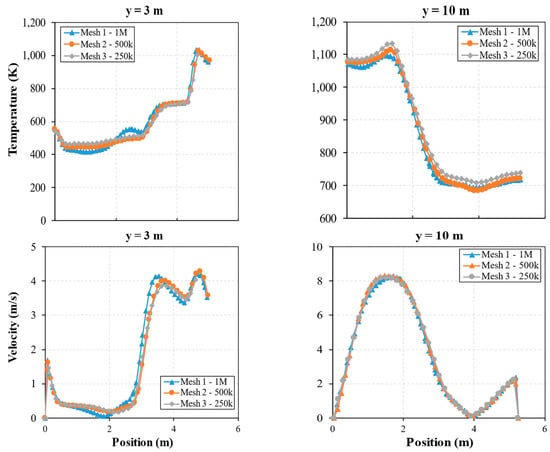
Figure 3.
Velocity and temperature profiles for the three meshes at heights of 3 and 10 m across the furnace width.
The differences are higher closer to the grate. Consequently, to achieve reliable CFD results, the mesh with the highest density was preferred and selected for the development of the subsequent simulations. Meshes denser than 1M cells were also assessed; however, the computational time was substantially higher, with no visible gains in accuracy.
4. Results and Discussion
4.1. Nominal Conditions
This section presents the CFD results of the previously selected mesh in more detail. First, regarding biomass conversion using the bed model, for the different thermal conversion stages of this process, since the primary air supply is split in the vibrating grate, three zones were considered along the grate length. For each zone, biomass conversion rates were specified based on observations in the biomass power plant, which broadly agree with data found in the literature [,,]. These conversion rates can be found in Figure 4. Through the mass and energy balances presented in the previous section, the gas flow rate and the composition of the flue gas that are supplied to the freeboard were estimated. This information was then set as inlet boundary conditions for each zone.
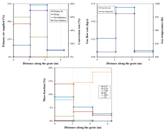
Figure 4.
Profiles of the different parameters considered in the bed conversion model along the grate and its result used as boundary conditions for the CFD simulation.
Regarding the numerical results, the method by which air is supplied to the boiler is one of the most important parameters in the combustion system. The design of the present boiler consists of two opposing arches to concentrate the flue gas and improve the mixing with the secondary air introduced in the side walls through small nozzles. In addition to the introduction of the oxidant in the main flue gas stream, its location is also important for improving the mixing and controlling the combustion process. The effect of the opposing arches and the multi-level small nozzles on the flow in the furnace can be observed in Figure 5, where the temperature and velocity contours in the middle plan of the model are presented. This design promotes concentration in the center zone of the furnace, where the velocity is higher.
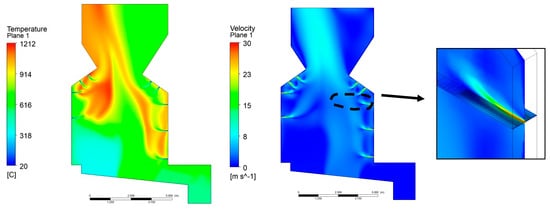
Figure 5.
Temperature and velocity profile in the middle plane.
The fastest reaction rates are found around the ignition air nozzles, where high-temperature gradients are observed. The boiler design was developed by Babcock & Wilcox [,] in the late 1970s specifically for biomass combustion and aimed to create a controlled combustion zone in the furnace. Secondary air nozzles within and below the arches penetrate and mix with the volatiles released from the bed. Furthermore, the two arches on the opposite walls define a combustion zone and create a smaller cross-section to promote the mixing of the combustion products. However, the result of inadequate penetration and the presence of arches is that the flow entering the upper furnace is deflected to the center, where the vertical velocity and temperature of the gases are high. This creates large temperature and velocity gradients in the flue gas flow entering the convection section of the furnace (superheater, evaporator, and economizer). The average temperature at the outlet of the domain was 994 °C.
In Figure 6, the velocity field is also illustrated by superimposing velocity vectors to present the flow’s dynamic behavior in the furnace’s upper part. Apart from the secondary air nozzles providing favorable reaction conditions in terms of oxygen, they also offer high turbulence levels in the arch zone. In turn, Figure 7 presents the profiles of the CO2, CO, and O2 mass fractions. A general characteristic of oxidation reactions is the occurrence of very fast rates in the secondary air injector regions. Secondary air injectors provide favorable reaction conditions in terms of oxygen and high turbulence levels, ensuring good mixing of the oxidant with the volatiles. The fastest reaction rates are found around secondary air jets due to the greater amount of oxygen for oxidation reactions. Thus, the location and design of these injectors are essential parameters in controlling the combustion process in the furnace. The heat released by the chemical reactions provides heat transfer by radiation to the surface of the fuel in the grate, thus promoting the initiation of the drying and devolatilization processes.
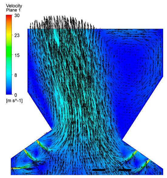
Figure 6.
Vorticity inside the boiler.

Figure 7.
Distribution of the CO, CO2, and O2 mass fractions.
Consequently, these injectors control and maintain the location of the reaction front on the fuel surface at a fixed position. This is important for obtaining an acceptable degree of fuel burn. Thus, the secondary air injectors in the arch of the furnace supply the necessary oxygen to complete the combustion of volatiles, mainly carbon monoxide. This can be observed by the contours of the mass fraction of both species. The small injectors of the air system mix the oxygen supplied by them with the gases released due to thermal decomposition, thus promoting the rapid oxidation of CO in the lower region of the furnace. The hottest regions in the furnace occur due to the oxidation of CO by the secondary air injectors. The regions where CO is around 0 and the CO2 is maximum correspond to the region where the maximum temperature was obtained. It is also important to mention that the oxidation reaction of CO is controlled not only by its mixing with oxygen but also by temperature. Additionally, CO is almost completely oxidized, and only the furnace’s central region contains this species due to the poor penetration of the secondary air nozzles. However, at the outlet of the furnace, an average mass fraction of CO of 0.009 (779 mg/m3) equivalent was obtained, meaning that a small quantity of energy is lost due to incomplete combustion.
Therefore, CO emissions are essentially related to the boiler design and the amount of air used in the combustion process. In this way, the mixing of volatiles with the combustion air could be improved if the penetration of the secondary air injectors was higher. Consequently, as can be observed in Figure 7, the CO released in the last sections of the grate does not react completely. Thus, by increasing the penetration of secondary air injectors, the oxidation of combustion products will be improved.
Regarding CO2 emissions, the average mass fraction calculated at the exit was 0.12. With this result, it is verified that the secondary air allows for the oxidation of CO since its input in the simulation had a maximum value of 0.08 (6.87% in volume). In contrast to the CO2 mass fraction contour, O2 presents the opposite trend due to its CO reaction forming CO2 by its consumption. At the outlet, the simulation pointed out a value of 9.5% (in volume), which is within the range of the data recorded during one week of regular operation in the biomass power plant and presented in []. Furthermore, during one of the monitoring campaigns to determine the emission levels of the power plant, the average CO, CO2, O2, and temperature in the upper part of the boiler were 719 mg/m3, 11.7%, 9.1%, and 1080 °C, respectively. The direct comparison of these values presents some discrepancies, which may be attributed to the variation in the operating conditions and the results of the bed model. In the grate, combustion instabilities and variations associated with the fuel feeding in terms of properties during the normal operation of the boiler are frequent, and it is difficult to predict the exact conditions for the CFD model. However, although direct experimental validation for the present boiler was not feasible, the predicted flue gas temperature (~1000–1200 °C) and outlet gas composition are consistent with values reported in recent CFD studies of biomass grate-fired boilers operating under comparable conditions. This agreement supports the physical acceptability of the model predictions and aligns with trends observed in other simulation-based analyses. For instance, Su et al. [,] developed a CFD model for a 130 tons/h biomass grate-fired boiler, where the predicted fluid flow inside the furnace exhibited similar characteristics, including maximum flue gas velocities of approximately 30 m/s driven by secondary air injection, as well as CO2, CO, and O2 concentrations within comparable ranges.
Furthermore, there are different phenomena associated with disturbances in the bed, like local burnout and channeling, which could be responsible for higher pollutant emissions and uneven fuel consumption. Therefore, the discrepancies can be understood, but even though there are some differences between the baseline and the experimental measurements, the baseline model allows one to capture the main flow and combustion features with acceptable accuracy.
Moreover, regarding the supply of air in the furnace, the poor mixing in this type of equipment is often due to the result of the utilization of relatively small diameters of the secondary air nozzles, which provide poor penetration into the flue gas flow. Consequently, a relatively simple solution to this problem would be to use fewer injectors but with a larger diameter [,,,]. However, the distribution of the injectors is also a very important factor in improving the combustion process in the furnace. If the space between injectors is too small, there will be poor mixing between oxygen and combustion products as the flow of air injected through the injectors will be affected. Choi et al. [] verified the same problem in a grate-type wood waste incinerator. The authors investigated how to reduce CO emissions by simply retrofitting the existing facility without installing any extra equipment and changing the existing operating conditions. The reduction in CO emissions was possible through a secondary air nozzle retrofit based on the jet penetration factor and the momentum flux ratio of a commercial wood waste incinerator, and a 3D CFD model was developed to predict how far beyond the limit the CO emissions would be after the retrofit. Kaer et al. [] also reported the poor mixing experienced in a straw-fired grate boiler due to the relatively small diameter of the secondary air nozzles, providing poor penetration into the bulk flow. The author proposed a relatively simple solution with fewer nozzles with a larger diameter. Another strategy was proposed by Jorgensen et al. [,]. These authors developed a numerical model to compare a conventional overfire air system design typically used on biomass furnaces to a new advanced design involving the removal of the arches and replacing the numerous small nozzles with a smaller number of controlled penetration nozzles.
4.2. Influence of the Biomass Conversion on the Grate
The purpose of this section is to demonstrate different combustion regimes that can occur during a biomass power plant operation. During the normal operation of an industrial boiler, the operating conditions are constantly varying, and there are combustion instabilities inside the fuel bed, the movement of the grate affecting the combustion, and variations in the physical and chemical properties of the fuel supply. Thus, it is important to present an overview of different scenarios in biomass conversion along the grate. Table 3 presents the cases defined for the evaluation of the combustion behavior inside the furnace as a function of different considerations in the bed conversion model. All the CFD simulations are based on the nominal operating conditions.

Table 3.
Cases defined for the analysis of the bed conversion model.
The differences between the different scenarios can be evaluated in Figure 8 and Figure 9. Figure 8 presents the velocity and temperature profiles in the middle plane of the computational domain. The combustion, evaluated based on the temperature and velocity field pattern, as observed in the previous results, is governed by the location of secondary air nozzles. Here, regarding the fluid flow configuration, although the conditions in the grate are not the same, the flow patterns are similar. Only case 4 presents a higher fluid flow in the last section of the grate since the bed conversion was shifted to this zone. Additionally, the comparison between the three cases indicates that a higher temperature on the left-hand side of the boiler was observed for case 3. Higher temperatures can cause severe deposition problems.
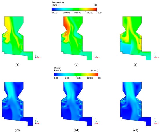
Figure 8.
Temperature and velocity contours of (a,a1) case 2, (b,b1) case 3, and (c,c1) case 4.
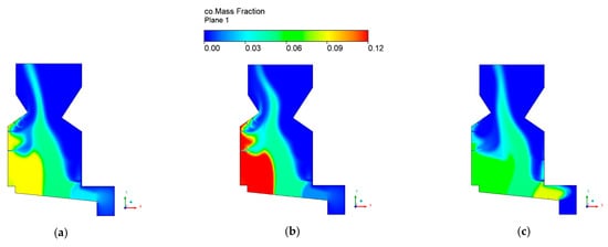
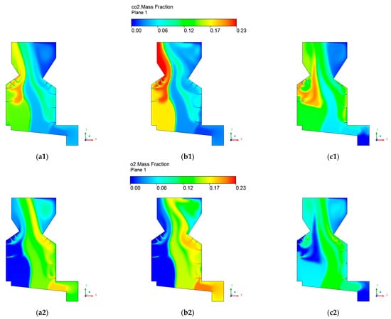
Figure 9.
CO, CO2, and O2 mass fractions contours for (a,a1,a2) case 2, (b,b1,b2) case 3, and (c,c1,c2) case 4.
In these conditions, secondary air nozzles must push the flame to the furnace center, and this is only possible with a higher flow rate. The result of this increase in temperature is attributed to the biomass conversion mainly in the first section of the grate and the reduction in the amount of energy for drying the fuel. Consequently, a higher amount of volatiles is released on the left side. Subsequently, their mixing with the air supplied by the secondary air nozzles leads to a different combustion behavior compared with the other cases. Hence, through the different scenarios, it is possible to verify the modifications in the combustion patterns in the freeboard.
In contrast to case 3, as a higher percentage of char conversion in the last part of the grate was considered for case 4, an increase in the temperature near the right wall of the boiler was observed. Therefore, apart from playing an important role in freeboard modeling, the bed model can capture the dynamic behavior or modifications of the bed conversion in the grate. Through Figure 9, it is possible to observe how the chemical reactions are sensitive to the grate inlet conditions.
The mass fraction contours are a useful tool for understanding and evaluating combustion phenomena. Although case 2 presents the highest CO mass fraction released to the furnace, the boiler design reduced its value considerably to 0.004, the lowest for the different cases tested. Hence, it is essential to highlight that the combustion efficiency is improved when the biomass conversion is in the first two sections of the grate. In addition, through this analysis, it can be concluded that if the thermal conversion of biomass is moved further downstream the grate, higher penetration of the secondary air nozzles is required.
4.3. Sensitivity Analysis of the Air Supply Conditions
Since the design of the air supply system plays a significant role in the efficient and complete combustion of biomass, CFD simulations were developed to investigate the influence of this part of the boiler. The split ratio of primary to secondary air in a modern grate-fired boiler is 60/40 [] while, in the biomass power plant, considering the nominal operating conditions (Table 1), it is approximately 79/21. Thus, there is considerable potential for improvement since, in the previous analyses, particular attention was oriented to the need for higher penetration of the secondary air nozzles.
Hence, considering the limitations concerning the air supply and the nominal operating conditions, two different cases were analyzed, modifying only the primary and secondary air split ratio. The first case was defined by considering the need for more secondary air and a high level of turbulence in the upper part of the furnace, resulting in a 40/60 split ratio. The second case was based on the split ratio value defined by Yin et al. [] for modern boilers: 60/40.
In the temperature profile illustrated in Figure 10, the highest temperature, around 2000 °C, was obtained in the first case and occurred due to the mixture of the flue gases with oxygen supplied by the lower secondary air injector present on the right-side wall of the boiler. Due to the higher amount of oxygen supplied by the secondary air injectors, the maximum peak temperature was obtained in this case when compared to the others.
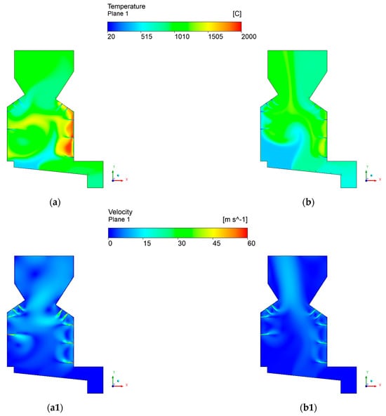
Figure 10.
Temperature and velocity contours for the different split ratio cases: (a,a1) 40/60 and (b,b1) 60/40.
Providing a higher secondary air flow rate allows more oxygen to be available for oxidation reactions. As a result of this retrofitting, a higher amount of energy is released inside the furnace. For this reason, in the case with a 40/60 split ratio, there is an increase in the average temperature inside the furnace to approximately 1050 °C compared to the 988 °C obtained for the second case.
It is interesting to note that, in case 1, due to the supply of a higher secondary air flow rate, the flow dynamics change significantly when compared to the results of the baseline model and 60/40 split ratio. It is possible to verify that, due to the higher penetration of the secondary air nozzles and, consequently, higher turbulence generated inside the furnace, the flow is more deflected toward the right wall when compared to the other cases. Hence, through the temperature contour, it is observed that the first injector on the left wall has a relevant role in determining the flow and promoting the flow’s displacement to the opposite side. The injectors that are inside the arches also direct the flow toward the lower central part of the boiler, thus promoting a better mixing of the flue gases with the air and increasing the residence time inside the boiler.
The CO reaction rate shows higher values in regions close to the secondary air nozzles. This is essentially due to the higher penetration of the secondary air nozzles and higher oxygen availability resulting from a higher flow rate of secondary air. Thus, CO is almost completely oxidized to CO2 and, at the outlet, the average mass fraction of CO is 0.0003, while, for the second case, its value is ten times higher. This proves that penetration of secondary air nozzles is a driving factor for promoting higher oxidation of combustion products.
Apart from the influence of the primary-to-secondary-air ratio, another interesting variable is the primary air temperature. Preheating primary air is a common practice to improve combustion behavior and increase the power plant’s efficiency. Hence, considering the previous results, the 40/60 split ratio configuration was selected to analyze the influence of the primary air temperature. In general, the temperature of the primary could reach temperatures up to 200 °C []. However, considering the results of Silva et al. [], temperatures around 100 °C are feasible for this particular boiler. Hence, a CFD simulation was performed to analyze the effect of preheating the primary air at 100 °C.
Figure 11 presents the temperature profile in the middle plane of the boiler, and it is possible to observe that higher temperatures are obtained inside the furnace. The profile is similar to the one obtained with a 40/60 split ratio; however, the effect of the primary air preheating is visible mainly near the right wall, where a region with a higher temperature is observed. Higher primary air temperatures also improved the boiler efficiency in terms of pollutant emissions.
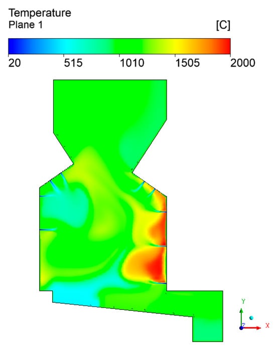
Figure 11.
Temperature field for the case with primary air heating.
Figure 12 compares the average mass fractions of CO, CO2, and O2 between the previous and present cases. Although the CO mass fraction was reduced, higher temperatures in the furnace can cause negative effects such as increased thermal NOx formation and the risk of grate and wall thermal damage. Considering these issues, the increase in the primary air temperature should be verified and carefully assessed for optimal combustion conditions since similar results can be obtained only by retrofitting the air combustion system.
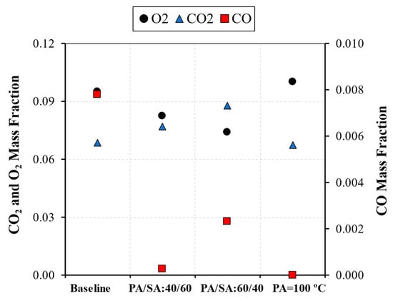
Figure 12.
Average CO, CO2, and O2 mass fractions at the outlet of the furnace for the different cases.
5. Conclusions
The growing use of biomass in power generation, combined with stricter emissions regulations, highlights the need for accurate, efficient, and cost-effective tools to support boiler design and operation. CFD modeling has become increasingly valuable due to advances in computational power and algorithm development, offering a flexible and time-effective alternative to experimental investigations. In this context, the present study developed and applied a CFD model integrated with a simplified empirical bed conversion model to simulate combustion in a 35 MWth industrial grate-fired boiler. The key findings are summarized as follows:
- The proposed CFD approach, coupled with a simplified bed model based on an experimentally derived volatile composition, proved effective in capturing the spatial evolution of combustion within the furnace. It serves as a practical engineering tool for analyzing design and nominal operating conditions.
- The simulations revealed the central role of the furnace’s contraction zone in shaping flow and combustion behavior. The flue gas tended to concentrate, driven by geometry, leading to temperature and velocity gradients downstream. CO emissions from the rear grate sections were found to be less completely oxidized under this configuration.
- Scenarios in which char combustion was shifted toward the rear of the grate resulted in temperature imbalances near boiler walls and increased reliance on secondary air jet penetration. Maintaining combustion toward the front sections improved CO oxidation and overall temperature uniformity.
- Adjusting the primary-to-secondary-air split ratio to 40/60 significantly enhanced secondary air jet penetration, improving mixing and reducing CO emissions by over 50% compared to the base case. This underscores the importance of secondary air injection design for effective pollutant control and thermal performance.
- Increasing the primary air temperature led to localized temperature gains and reduced CO emissions, particularly near the right boiler wall. However, this also introduced potential risks, such as increased thermal NOx formation and material degradation, suggesting the need for further evaluation before implementation.
These results illustrated how simplified empirical bed models can be effectively integrated into CFD simulations to represent biomass combustion dynamics in industrial systems. Despite the simplifications, the model accurately reproduced physical trends and provided insights into how combustion, air distribution, and operational adjustments affect efficiency and emissions. Practically, the findings offer guidance for optimizing combustion strategy and retrofitting operations in biomass-fired boilers.
The model relies on devolatilization data obtained from small-scale reactor experiments at 800 °C. While empirical values were adjusted to reflect boiler-scale behavior, scaling introduces uncertainties due to differences in heat and mass transfer rates, particle interactions, and turbulence–chemistry coupling. Additionally, the CFD model employed a first-order upwind scheme to ensure numerical stability, which may limit accuracy in capturing fine gradients. The absence of experimental validation data and limited focus on emissions beyond CO, such as NOx, are also noted limitations.
Based on these observations, the authors recommend the following directions for future work: incorporating experimental measurements from the operating boiler for model calibration and quantitative validation, exploring higher-order discretization schemes to improve solution accuracy, and extending the model to include NOx formation mechanisms and their dependence on temperature profiles.
Despite these limitations, the present work contributes to the field by demonstrating a simplified yet robust approach to modeling grate-fired biomass combustion, bridging the gap between empirical experimentation and full-scale industrial application. The model offers a foundation for improved combustion efficiency, pollutant reduction, and informed operational strategies, paving the way for future advancements in biomass boiler technology.
Author Contributions
Conceptualization, J.C.T.; Methodology, J.P.S. and J.C.T.; Investigation, J.P.S.; Writing—original draft, J.P.S.; Writing—review & editing, J.P.S., S.T. and J.C.T.; Supervision, S.T. and J.C.T.; Funding acquisition, S.T. and J.C.T. All authors have read and agreed to the published version of the manuscript.
Funding
This research was funded by Portuguese Foundation for Science and Technology (FCT)grant number SFRH/BD/130588/2017.
Data Availability Statement
The original contributions presented in this study are included in the article. Further inquiries can be directed to the corresponding author.
Acknowledgments
The first author would like to express his acknowledgment for the support given by the Portuguese Foundation for Science and Technology (FCT) through the PhD grant SFRH/BD/130588/2017. FCT has supported this work within the R&D Units Project Scope UIDB/00319/2020 (ALGORITMI) and R&D Units Project Scope UIDP/04077/2020 (MEtRICs).
Conflicts of Interest
The authors declare no conflict of interest.
Abbreviations
| Pre-exponential factor (s−1) or empirical constant (-) | |
| Specific heat (J/kg.K) | |
| Activation energy (J/mol) | |
| Mass flow rate (kg/s) | |
| Heat flux (W) | |
| Energy (J) | |
| Temperature (K) | |
| Temperature exponent (-) | |
| Mass fraction (-) | |
| Initial | |
| Instantaneous | |
| Radiation | |
| Volatiles |
References
- da Costa, T.P.; Quinteiro, P.; Tarelho, L.A.d.C.; Arroja, L.; Dias, A.C. Environmental impacts of forest biomass-to-energy conversion technologies: Grate furnace vs. fluidised bed furnace. J. Clean. Prod. 2018, 171, 153–162. [Google Scholar] [CrossRef]
- Chaney, J.; Liu, H.; Li, J. An overview of CFD modelling of small-scale fixed-bed biomass pellet boilers with preliminary results from a simplified approach. Energy Convers. Manag. 2012, 63, 149–156. [Google Scholar] [CrossRef]
- Khodaei, H.; Al-Abdeli, Y.M.; Guzzomi, F.; Yeoh, G.H. An overview of processes and considerations in the modelling of fixed-bed biomass combustion. Energy 2015, 88, 946–972. [Google Scholar] [CrossRef]
- Silva, J.P.; Teixeira, S.; Peters, B.; Teixeira, J.C. Survey of Existing Literature Data on the Biomass Combustion Behavior in Industrial Grate-Fired Boilers. In Proceedings of the ASME 2021 International Mechanical Engineering Congress and Exposition, Virtual, 1–5 November 2021; American Society of Mechanical Engineers: New York, NY, USA, 2021; Volume 8A: Energy. [Google Scholar] [CrossRef]
- Kim, S.; Shin, D.; Choi, S. Comparative evaluation of municipal solid waste incinerator designs by flow simulation. Combust. Flame 1996, 106, 241–251. [Google Scholar] [CrossRef]
- Griselin, N.; Bai, X.S. Particle Dynamics in a Biomass-Fired Furnace—Predictions of Solid Residence Changes with Operation. IFRF Combust. J. 2000, 30, 3290616. [Google Scholar]
- Frey, H.-H.; Peters, B.; Hunsinger, H.; Vehlow, J. Characterization of municipal solid waste combustion in a grate furnace. Waste Manag. 2003, 23, 689–701. [Google Scholar] [CrossRef] [PubMed]
- Scharler, R.; Obernberger, I. Numerical Modelling of Biomass Grate Furnaces. In Proceedings of the 5th Conference on Industrial Furnaces and Boilers, Porto, Portugal, 11–14 April 2000; Volume 17. [Google Scholar]
- Scharler, R.; Fleckl, T.; Obernberge, I. Modification of a Magnussen Constant of the Eddy Dissipation Model for biomass grate furnaces by means of hot gas in-situ FT-IR absorption spectroscopy, Progress in Computational Fluid Dynamics. Int. J. 2003, 3, 102. [Google Scholar] [CrossRef]
- Klason, T.; Bai, X.S. Combustion process in a biomass grate fired industry furnace: A CFD study. Prog. Comput. Fluid Dyn. Int. J. 2006, 6, 278. [Google Scholar] [CrossRef]
- Klason, T.; Bai, X.S.; Bahador, M.; Nilsson, T.K.; Sundén, B. Investigation of radiative heat transfer in fixed bed biomass furnaces. Fuel 2008, 87, 2141–2153. [Google Scholar] [CrossRef]
- Yin, C.; Rosendahl, L.A.; Kær, S.K.; Clausen, S.; Hvid, S.L.; Hille, T. Mathematical modeling and experimental study of biomass combustion in a thermal 108 MW grate-fired boiler. Energy Fuels 2008, 22, 1380–1390. [Google Scholar] [CrossRef]
- Yin, C.; Rosendahl, L.; Clausen, S.; Hvid, S.L. Characterizing and modeling of an 88 MW grate-fired boiler burning wheat straw: Experience and lessons. Energy 2012, 41, 473–482. [Google Scholar] [CrossRef]
- Paper, C.; Universit, F.A.; Costa, M.; National, I.; Universit, A.M.; Pegaso, T. Experimental and numerical analysis of a waste-to-energy plant operation. In Proceedings of the ASME-ATI-UIT 2015 Conference on Thermal Energy Systems: Production, Storage, Utilization and the Environment, Napoli, Italy, 17–20 May 2015. [Google Scholar]
- Costa, M.; Curcio, C.; Piazzullo, D.; Rocco, V.; Tuccillo, R. RDF incineration modelling trough thermo-chemical conversion and gaseous combustion coupling. Energy 2018, 161, 974–987. [Google Scholar] [CrossRef]
- Tu, Y.; Zhou, A.; Xu, M.; Yang, W.; Siah, K.B.; Prabakaran, S. Experimental and numerical study on the combustion of a 32 MW wood-chip grate boiler with internal flue gas recirculation technology. Energy Procedia 2017, 143, 591–598. [Google Scholar] [CrossRef]
- Tu, Y.; Zhou, A.; Xu, M.; Yang, W.; Siah, K.B.; Subbaiah, P. NOX reduction in a 40 t/h biomass fired grate boiler using internal flue gas recirculation technology. Appl. Energy 2018, 220, 962–973. [Google Scholar] [CrossRef]
- Kær, S.K. Numerical modelling of a straw-fired grate boiler. Fuel 2004, 83, 1183–1190. [Google Scholar] [CrossRef]
- Huttunen, M.; Kjäldman, L.; Saastamoinen, J. Analysis of grate firing of wood with numerical flow simulation. IFRF Combust. J. 2004, 18, 200401. [Google Scholar]
- Goddard, C.D.; Yang, Y.B.; Goodfellow, J.; Sharifi, V.N.; Swithenbank, J.; Chartier, J.; Mouquet, D.; Kirkman, R.; Barlow, D.; Moseley, S. Optimisation study of a large waste-to-energy plant using computational modelling and experimental measurements. J. Energy Inst. 2005, 78, 106–116. [Google Scholar] [CrossRef]
- Kær, S.K. Straw combustion on slow-moving grates—A comparison of model predictions with experimental data. Biomass Bioenergy 2005, 28, 307–320. [Google Scholar] [CrossRef]
- Yang, Y.B.; Newman, R.; Sharifi, V.; Swithenbank, J.; Ariss, J. Mathematical modelling of straw combustion in a 38 MWe power plant furnace and effect of operating conditions. Fuel 2007, 86, 129–142. [Google Scholar] [CrossRef]
- Venturini, P.; Borello, D.; Iossa, C.; Lentini, D.; Rispoli, F. Modeling of multiphase combustion and deposit formation in a biomass-fed furnace. Energy 2010, 35, 3008–3021. [Google Scholar] [CrossRef]
- Yu, Z.; Ma, X.; Liao, Y. Mathematical modeling of combustion in a grate-fired boiler burning straw and effect of operating conditions under air- and oxygen-enriched atmospheres. Renew. Energy 2010, 35, 895–903. [Google Scholar] [CrossRef]
- Zhang, X.; Chen, Q.; Bradford, R.; Sharifi, V.; Swithenbank, J. Experimental investigation and mathematical modelling of wood combustion in a moving grate boiler. Fuel Process. Technol. 2010, 91, 1491–1499. [Google Scholar] [CrossRef]
- Cordiner, S.; Manni, A.; Mulone, V.; Rocco, V. A Detailed Study of a Multi-MW Biomass Combustor by Numerical Analysis: Evaluation of Fuel Characteristics Impact. Energy Procedia 2014, 61, 751–755. [Google Scholar] [CrossRef]
- Chen, Q.; Zhang, X.; Zhou, J.; Sharifi, V.N.; Swithenbank, J. Effects of Flue Gas Recirculation on Emissions from a Small Scale Wood Chip Fired Boiler. Energy Procedia 2015, 66, 65–68. [Google Scholar] [CrossRef]
- Costa, M.; Dell’Isola, M.; Massarotti, N. Numerical analysis of the thermo-fluid-dynamic field in the combustion chamber of an incinerator plant. Energy 2009, 34, 2075–2086. [Google Scholar] [CrossRef]
- Costa, M.; Dell’Isola, M.; Massarotti, N. Temperature and residence time of the combustion products in a waste-to-energy plant. Fuel 2012, 102, 92–105. [Google Scholar] [CrossRef]
- Costa, M.; Indrizzi, V.; Massarotti, N.; Mauro, A. Modeling and optimization of an incinerator plant for the reduction of the environmental impact. Int. J. Numer. Methods Heat Fluid Flow 2015, 25, 1463–1487. [Google Scholar] [CrossRef]
- Rajh, B.; Yin, C.; Samec, N.; Hriberšek, M.; Zadravec, M. Advanced modelling and testing of a 13 MWth waste wood-fired grate boiler with recycled flue gas. Energy Convers. Manag. 2016, 125, 230–241. [Google Scholar] [CrossRef]
- Rajh, B.; Yin, C.; Samec, N.; Hriberšek, M.; Kokalj, F.; Zadravec, M. Advanced CFD modelling of air and recycled flue gas staging in a waste wood-fired grate boiler for higher combustion efficiency and greater environmental benefits. J. Environ. Manag. 2018, 218, 200–208. [Google Scholar] [CrossRef]
- Yang, Y.B.; Goh, Y.R.; Zakaria, R.; Nasserzadeh, V.; Swithenbank, J. Mathematical modelling of MSW incineration on a travelling bed. Waste Manag. 2002, 22, 369–380. [Google Scholar] [CrossRef]
- Duffy, N.T.M.; Eaton, J.A. Investigation of factors affecting channelling in fixed-bed solid fuel combustion using CFD. Combust. Flame 2013, 160, 2204–2220. [Google Scholar] [CrossRef]
- Duffy, N.T.M.; Eaton, J.A. Investigation of 3D flow and heat transfer in solid-fuel grate combustion: Measures to reduce high-temperature degradation. Combust. Flame 2016, 167, 422–443. [Google Scholar] [CrossRef]
- Galletti, C.; Giomo, V.; Giorgetti, S.; Leoni, P.; Tognotti, L. Biomass furnace for externally fired gas turbine: Development and validation of the numerical model. Appl. Therm. Eng. 2016, 96, 372–384. [Google Scholar] [CrossRef]
- Patronelli, S.; Antonelli, M.; Tognotti, L.; Galletti, C. Combustion of wood-chips in a small-scale fixed-bed boiler: Validation of the numerical model through in-flame measurements. Fuel 2018, 221, 128–137. [Google Scholar] [CrossRef]
- Mätzing, H.; Gehrmann, H.-J.; Seifert, H.; Stapf, D. Modelling grate combustion of biomass and low rank fuels with CFD application. Waste Manag. 2018, 78, 686–697. [Google Scholar] [CrossRef]
- Netzer, C.; Li, T.; Seidel, L.; Mauß, F.; Løvås, T. Stochastic Reactor-Based Fuel Bed Model for Grate Furnaces. Energy Fuels 2020, 34, 16599–16612. [Google Scholar] [CrossRef]
- Simsek, E.; Brosch, B.; Wirtz, S.; Scherer, V.; Krüll, F. Numerical simulation of grate firing systems using a coupled CFD/discrete element method (DEM). Powder Technol. 2009, 193, 266–273. [Google Scholar] [CrossRef]
- Mahmoudi, A.H.; Besseron, X.; Hoffmann, F.; Markovic, M.; Peters, B. Modeling of the biomass combustion on a forward acting grate using XDEM. Chem. Eng. Sci. 2016, 142, 32–41. [Google Scholar] [CrossRef]
- Wissing, F.; Wirtz, S.; Scherer, V. Simulating municipal solid waste incineration with a DEM/CFD method—Influences of waste properties, grate and furnace design. Fuel 2017, 206, 638–656. [Google Scholar] [CrossRef]
- Somwangthanaroj, S.; Fukuda, S. CFD modeling of biomass grate combustion using a steady-state discrete particle model (DPM) approach. Renew. Energy 2019, 148, 363–373. [Google Scholar] [CrossRef]
- Jordan, C.; Harasek, M. Improvement of a combustion unit based on a grate furnace for granular dry solid biofuels using CFD methods. Heat Transf. Eng. 2010, 31, 774–781. [Google Scholar] [CrossRef]
- Kurz, D.; Schnell, U.; Scheffknecht, G. CFD simulation of wood chip combustion on a grate using an Euler–Euler approach. Combust. Theory Model. 2012, 16, 251–273. [Google Scholar] [CrossRef]
- Kurz, D.; Schnell, U.; Scheffknecht, G. Euler-Euler simulation of wood chip combustion on a grate—Effect of fuel moisture content and full scale application. Prog. Comput. Fluid Dyn. Int. J. 2013, 13, 322. [Google Scholar] [CrossRef]
- Karim, M.R.; Naser, J. CFD modelling of combustion and associated emission of wet woody biomass in a 4 MW moving grate boiler. Fuel 2018, 222, 656–674. [Google Scholar] [CrossRef]
- Rezeau, A.; Díez, L.I.; Royo, J.; Díaz-Ramírez, M. Efficient diagnosis of grate-fired biomass boilers by a simplified CFD-based approach. Fuel Process. Technol. 2018, 171, 318–329. [Google Scholar] [CrossRef]
- Bermúdez, C.A.; Porteiro, J.; Varela, L.G.; Chapela, S.; Patiño, D. Three-dimensional CFD simulation of a large-scale grate-fired biomass furnace. Fuel Process. Technol. 2020, 198, 106219. [Google Scholar] [CrossRef]
- Zadravec, T.; Yin, C.; Kokalj, F.; Samec, N.; Rajh, B. The impacts of different profiles of the grate inlet conditions on freeboard CFD in a waste wood-fired grate boiler. Appl. Energy 2020, 268, 115055. [Google Scholar] [CrossRef]
- Costa, M.; Massarotti, N.; Indrizzi, V.; Rajh, B.; Yin, C.; Samec, N. Engineering bed models for solid fuel conversion process in grate-fired boilers. Energy 2014, 77, 244–253. [Google Scholar] [CrossRef]
- Thunman, H.; Niklasson, F.; Johnsson, F.; Leckner, B. Composition of volatile gases and thermochemical properties of wood for modeling of fixed or fluidized beds. Energy Fuels 2001, 15, 1488–1497. [Google Scholar] [CrossRef]
- Neves, D.; Thunman, H.; Matos, A.; Tarelho, L.; Gómez-Barea, A. Characterization and prediction of biomass pyrolysis products. Prog. Energy Combust. Sci. 2011, 37, 611–630. [Google Scholar] [CrossRef]
- Mehrabian, R.; Shiehnejadhesar, A.; Scharler, R.; Obernberger, I. Multi-physics modelling of packed bed biomass combustion. Fuel 2014, 122, 164–178. [Google Scholar] [CrossRef]
- Wilcox, B. Steam: Its Generation and Use, 40th ed.; Babcock & Wilcox Enterprises, Inc.: Barberton, South Africa, 1992. [Google Scholar]
- Silva, J.P.; Teixeira, S.; Grilo, É.; Peters, B.; Teixeira, J.C. Analysis and monitoring of the combustion performance in a biomass power plant. Clean. Eng. Technol. 2021, 5, 100334. [Google Scholar] [CrossRef]
- Silva, J.P.; Teixeira, S.; Teixeira, J.C. Characterization of the physicochemical and thermal properties of different forest residues. Biomass Bioenergy 2023, 175, 106870. [Google Scholar] [CrossRef]
- Silva, J.; Castro, C.; Teixeira, S.; Teixeira, J. Evaluation of the Gas Emissions during the Thermochemical Conversion of Eucalyptus Woodchips. Processes 2022, 10, 2413. [Google Scholar] [CrossRef]
- Fraga, L.G.; Silva, J.; Teixeira, J.C.; Ferreira, M.E.C.; Teixeira, S.F.; Vilarinho, C.; Gonçalves, M.M. Study of Mass Loss and Elemental Analysis of Pine Wood Pellets in a Small-Scale Reactor. Energies 2022, 15, 5253. [Google Scholar] [CrossRef]
- Silva, J.P.; Teixeira, S.; Teixeira, J.C. Thermogravimetric Assessment and Kinetic Analysis of Forestry Residues Combustion. Energies 2025, 18, 3299. [Google Scholar] [CrossRef]
- Yang, Y.B.; Yamauchi, H.; Nasserzadeh, V.; Swithenbank, J. Effects of fuel devolatilisation on the combustion of wood chips and incineration of simulated municipal solid wastes in a packed bed. Fuel 2003, 82, 2205–2221. [Google Scholar] [CrossRef]
- Magnussen, B.F.; Hjertager, B.H. On mathematical modeling of turbulent combustion with special emphasis on soot formation and combustion. Symp. Int. Combust. 1977, 16, 719–729. [Google Scholar] [CrossRef]
- Magnussen, B. On the structure of turbulence and a generalized eddy dissipation concept for chemical reaction in turbulent flow. In Proceedings of the 19th Aerospace Sciences Meeting, St. Louis, MO, USA, 12–15 January 1981; American Institute of Aeronautics and Astronautics: Reston, VA, USA, 1981. [Google Scholar] [CrossRef]
- Chapela, S.; Porteiro, J.; Costa, M. Effect of the Turbulence–Chemistry Interaction in Packed-Bed Biomass Combustion. Energy Fuels 2017, 31, 9967–9982. [Google Scholar] [CrossRef]
- Shiehnejadhesar, A.; Mehrabian, R.; Scharler, R.; Goldin, G.M.; Obernberger, I. Development of a gas phase combustion model suitable for low and high turbulence conditions. Fuel 2014, 126, 177–187. [Google Scholar] [CrossRef]
- Shiehnejadhesar, A.; Scharler, R.; Mehrabian, R.; Obernberger, I. Development and validation of CFD models for gas phase reactions in biomass grate furnaces considering gas streak formation above the packed bed. Fuel Process. Technol. 2015, 139, 142–158. [Google Scholar] [CrossRef]
- Rajh, B.; Yin, C.; Samec, N. CFD modeling and experience of waste-to-energy plant burning waste wood. In Proceedings of the 14th International Waste Management and Landfill Symposium, Cagliari, Italy, 30 September–4 October 2013; Volume 13. [Google Scholar]
- Strempek, J.R.; Jorgensen, K.L. Use of Numerical Modeling to Compare Overfire Air Systems on Stoker-Fired Furnaces. In Proceedings of the ASME 2008 International Mechanical Engineering Congress and Exposition, Boston, MA, USA, 31 October–6 November 2008; Volume 9. [Google Scholar] [CrossRef]
- Su, X.; Ma, L.; Fang, Q.; Yin, C.; Zhuang, H.; Qiao, Y.; Zhang, C.; Chen, G. Optimizing biomass combustion in a 130 t/h grate boiler: Assessing gas-phase reaction models and primary air distribution strategies. Appl. Therm. Eng. 2024, 238, 122043. [Google Scholar] [CrossRef]
- Su, X.; Fang, Q.; Ma, L.; Zhang, C.; Chen, G.; Yin, C.; Yang, W. Efficient and low-NO combustion in a grate-fired boiler by feeding biomass non-uniformly along grate width: An integrated modeling study with experimental validation. Energy 2024, 312, 133583. [Google Scholar] [CrossRef]
- Choi, C.; Choi, W.S.; Choi, J.H.; Kim, W.J.; Shin, D. Reducing CO emissions through a secondary air nozzle retrofit based on the jet penetration factor and the momentum flux ratio of a commercial wood waste incinerator. Appl. Therm. Eng. 2017, 118, 101–112. [Google Scholar] [CrossRef]
- Jorgensen, K.L.; Wessel, R.; Strempek, J. Numerical Simulation of Combustion Air Systems for Large Industrial Boilers. In Proceedings of the ASME 2002 International Mechanical Engineering Congress and Exposition, New Orleans, LA, USA, 17–22 November 2002; p. 8. [Google Scholar]
- Yin, C.; Rosendahl, L.A.; Søren, K. Grate-firing of biomass for heat and power production. Prog. Energy Combust. Sci. 2008, 34, 725–754. [Google Scholar] [CrossRef]
- Yan, M.; Antoni; Wang, J.; Hantoko, D.; Kanchanatip, E. Numerical investigation of MSW combustion influenced by air preheating in a full-scale moving grate incinerator. Fuel 2021, 285, 119193. [Google Scholar] [CrossRef]
Disclaimer/Publisher’s Note: The statements, opinions and data contained in all publications are solely those of the individual author(s) and contributor(s) and not of MDPI and/or the editor(s). MDPI and/or the editor(s) disclaim responsibility for any injury to people or property resulting from any ideas, methods, instructions or products referred to in the content. |
© 2025 by the authors. Licensee MDPI, Basel, Switzerland. This article is an open access article distributed under the terms and conditions of the Creative Commons Attribution (CC BY) license (https://creativecommons.org/licenses/by/4.0/).