Article

Research on Unwinding Mechanism Design and Tension Control Strategy for Winding Machines

School of Mechanical Engineering, Baoji University of Arts and Sciences, Baoji 721013, China
*
Author to whom correspondence should be addressed.
Processes 2025, 13(8), 2612; https://doi.org/10.3390/pr13082612
Submission received: 14 July 2025 / Revised: 2 August 2025 / Accepted: 12 August 2025 / Published: 18 August 2025

Abstract

During the winding process of a coil winding machine, excessive tension can cause wire deformation, over-stretching, or breakage, while insufficient tension may lead to slackness, accumulation, and wrinkling. The magnitude of winding tension directly affects product quality and operational performance. This paper addresses the challenges of inadequate constant-tension control accuracy and excessive fluctuations in the unwind system of winding machines under disturbances. By integrating specific operational scenarios, a fuzzy PID control strategy suitable for actual production environments is designed. Based on an established coupling model relating unwind tension to roll diameter, unwind speed, and moment of inertia, conventional PID and fuzzy PID control simulation models are developed in the MATLAB/Simulink platform. These models evaluate both control strategies under noise disturbances and abrupt tension changes. A systematic comparative analysis examines the dynamic response characteristics, steady-state accuracy, and anti-interference capabilities. Results demonstrate that the fuzzy PID control, integrated with actual winding machine conditions, effectively suppresses tension fluctuations induced by nonlinear disturbances, reducing adjustment time by 3 s compared to conventional PID control. This indicates that the production-condition-integrated fuzzy PID control exhibits smaller overshoot, enhanced robustness, and superior dynamic response and better meets precision requirements for wire winding tension control.

1. Introduction

Winding machines are specialized equipment used to complete the winding of various coils and are widely applied in the production of electromagnetic devices such as motors and transformers [1,2]. The advent of winding machines has solved problems such as inaccurate coil count and uneven wire layer arrangement that are prone to occur in manual winding, significantly enhancing the degree of production automation and product quality and strengthening the core competitiveness of products [3,4]. The unwinding mechanism, as a core functional unit of winding machines, undertakes crucial tasks such as wire material transportation, tension regulation, and dynamic stability. The design quality and tension control accuracy of the unwinding mechanism directly determine the quality consistency of the coiled products [5,6].
At present, the research on the unwinding tension control system of the winding machine mainly focuses on the optimization of the control system’s actuators and control strategies [7]. The research on the control mechanism mainly concentrates on magnetic powder tension control mechanisms, motor tension control mechanisms, and electro-hydraulic tension control mechanisms [8,9,10].
In terms of control strategies, conventional PID control, due to its straightforward structural design and strong adaptability, is extensively utilized in various tension control scenarios [11,12]. To ensure steel strip quality, Ahn et al. [13] implemented conventional PID control, cross-gain PID control, and standard PID control for tension regulation in the finishing mill of hot-rolled strips. Experimental comparisons demonstrated that PID control offers simplicity and ease of industrial implementation. Ju et al. [14] developed a nonlinear PID controller to address tension errors in the accumulator of roll-to-roll substrate systems. Simulation results indicated that the proposed controller maintains tension errors within 0–0.02 N, exhibiting excellent robustness. Li et al. [15] designed a PID control strategy to resolve uneven wire tension in electrical discharge machining processes. Experimental data revealed a 50% reduction in wire tension fluctuations with this system. Cheng et al. [16] implemented a PID controller in automated fiber placement to mitigate severe fiber vibration and tension instability. Tests confirmed superior control accuracy over traditional systems under significant speed disturbances. Thiffautt C. et al. [17] addressed instability in a paper towel tension control system by employing conventional PID control, successfully resolving unstable tension during paper roll winding. Huang et al. [18] applied this algorithm in spinning processes with simulation verification, confirming the system’s stability. Gu et al. [19] implemented conventional PID control in a full-digital tension control system for ultra-fine enameled wire (0.08 mm diameter), with results indicating satisfactory transient/steady-state performance and anti-interference capabilities. Despite its advantages, conventional PID control exhibits limitations such as parameter tuning lag and insufficient anti-interference ability when applied to complex, high-dynamic, time-varying, non-linear winding systems [20]. Xiao et al. [21] optimized parameters via fuzzy control in loom warp tension applications, with simulations and experiments confirming effective tension fluctuation reduction. Zheng et al. [22] developed a dedicated adaptive control system for warp knitting machines, achieving adaptive yarn tension regulation and demonstrating at least 55.2% reduction in tension peaks versus traditional systems, thereby validating superior performance. Tu et al. [23] proposed a fuzzy adaptive PID control system to enhance warp beam tension stability in sizing processes. Simulation results demonstrated significantly reduced tension fluctuations compared to conventional PID control, with oscillation amplitude decreasing by 64.49% under various speed step disturbances. Liu et al. [24] implemented adaptive fuzzy PID control for warp tension regulation in multilayer diagonal carbon fiber looms. Simulations verified superior tracking performance with reduced tension fluctuations over conventional PID control. Li et al. [25] developed an integral-separation fuzzy PID algorithm based on manufacturing processes to ensure strip tension stability during processing. Experimental validation showed approximately 40% reduction in tension fluctuation ranges during production.
Although there have been numerous studies on tension control algorithms, most existing research focuses on specific process scenarios, and a universal solution for nonlinear systems has yet to be established. The winding machine industry commonly faces the technical bottleneck of insufficient accuracy with conventional PID control [26]. This paper is dedicated to constructing a constant-tension unwinding system for winding machines combining high reliability, excellent dynamic response characteristics, and strong robustness. By constructing a multi-coupled nonlinear time-varying system model, the issues of tension overshoot in conventional PID control and disturbances from multi-physical-field coupling are resolved, enhancing winding accuracy. This constant-tension unwinding system provides theoretical support for overcoming the technical bottlenecks in high-end winding equipment.

2. Design of Constant Tension Unwinding Mechanism for Wire Winding Machines

2.1. Design Requirements

The design requirements of the winding machine critically determine the structural design of its mechanical components, encompassing both design parameters and functional specifications [27].

2.1.1. Parameter Requirements

The key parameters encompass overall dimensions, total mass, and related specifications. Specific design parameters for the automatic stranded-wire pin winding machine are listed in Table 1.

2.1.2. Functional Requirements

The constant-tension unwinding mechanism must perform unwinding, automatic wire twisting, constant-tension control, and broken-wire alarming. During operation, the winding machine achieves rapid multi-wire automatic twisting through synchronized timing control while maintaining adjustable tension setpoints for each wire bundle throughout the process.

2.2. Design Criteria

To ensure the safe, reliable, and efficient operation of the designed automatic wire winding machine for pin insertion, the following criteria should be considered during the design process:
(1)
Functionality Criterion: The winding machine must execute core processes and accommodate wires of varying diameters to meet diverse production requirements.
(2)
Equal Strength Principle: Structural dimensions should ensure uniform load-bearing capacity across components, eliminating localized over/under-strength areas. This avoids the “weakest link” effect, promotes homogeneous stress distribution, optimizes material utilization, reduces weight, and lowers costs.
(3)
Reliability and Lifetime Criterion: Design must account for component failure modes through appropriate material selection and structural optimization. Redundant design elements should be incorporated to enhance fault tolerance.
(4)
Safety Criterion: Hazards must be minimized by reducing high-risk moving parts, implementing fixed guards, and installing interlocking devices.
(5)
Cost and Manufacturability: Technical solutions should balance economic feasibility while meeting functional and quality standards. Overly complex designs that increase production costs must be avoided.

2.3. Structural Design

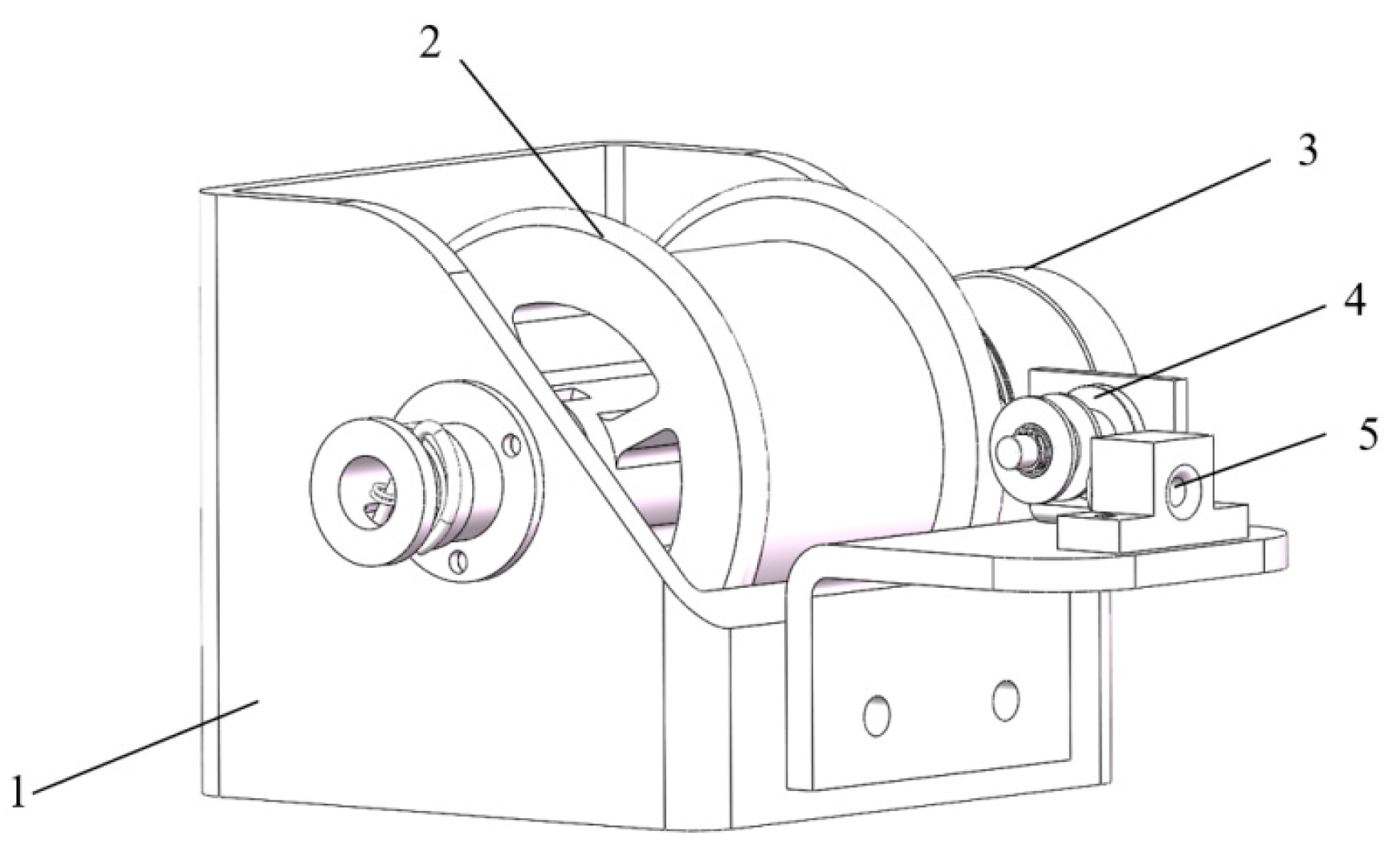
The constant tension unwinding mechanism of the winding machine mainly consists of the base, main shaft, planetary gear train, shuttle frame, magnetic powder brake, guide ring, and other components. Its three-dimensional model is shown in Figure 1. The servo motor and reducer are installed on the fixed seat, which is fixed to the base by bolts. The output shaft of the reducer is connected to the power wheel, driving the synchronous belt installed on the power wheel. The synchronous belt then drives the main shaft to rotate at a certain speed. During operation, the main shaft must both bear a certain load and rotate rapidly. To achieve both static and dynamic balance, it is designed as a hollow shaft with uniform mass distribution. The main shaft is connected to the turntable, driving it to rotate. The turntable is connected to gears to form a planetary gear train, which is used to complete the twisting of three strands of wire. Three shuttle frames are installed on the turntable, as shown in Figure 2, to perform wire unwinding and constant tension control. In front of the shuttle frame, there is a guide ring fixed to the main shaft by screws, rotating synchronously with the turntable. Below the guide ring, there is a stopper rod used for wire breakage detection.

3. Unwind System Tension Control Model

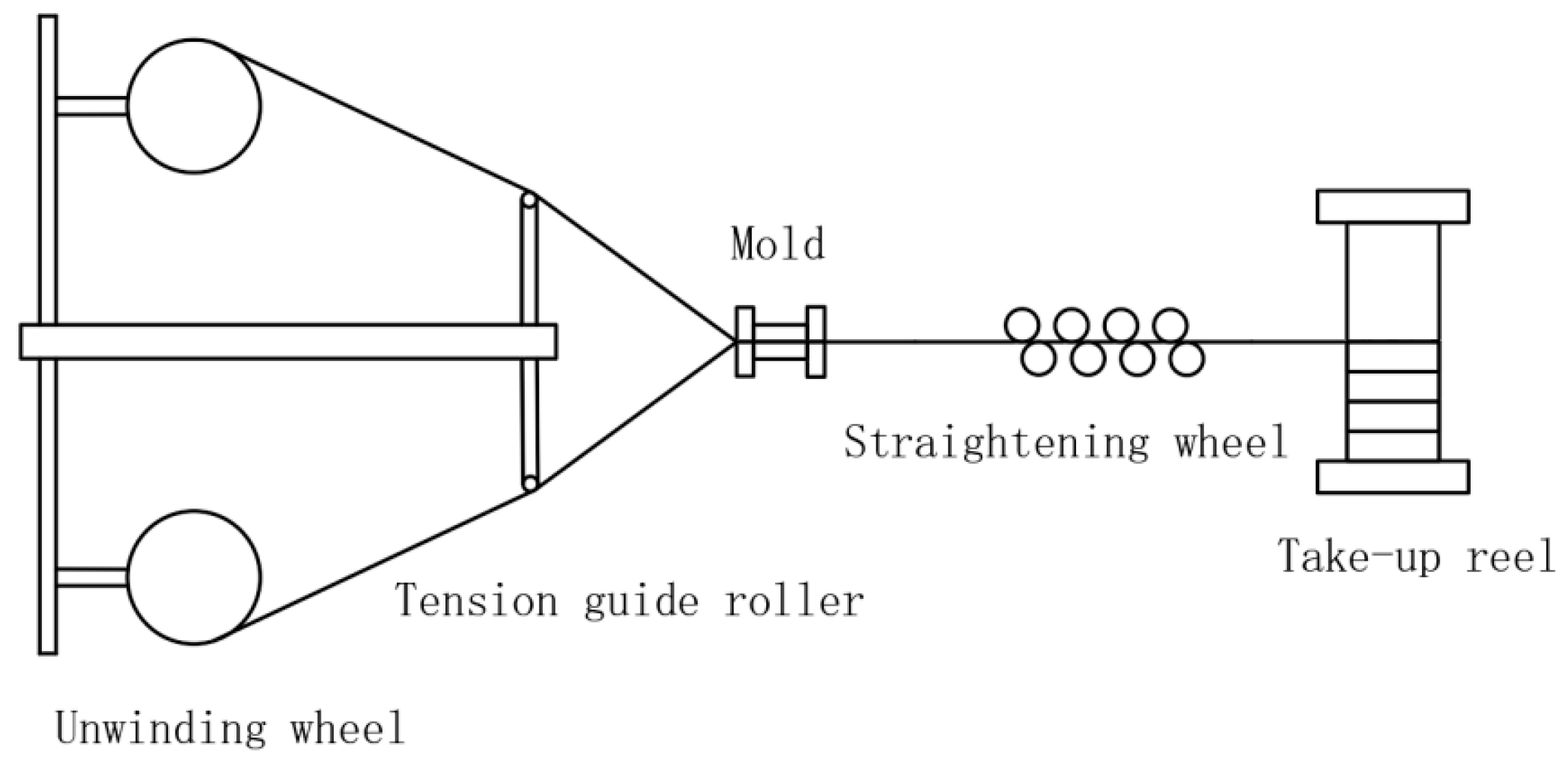
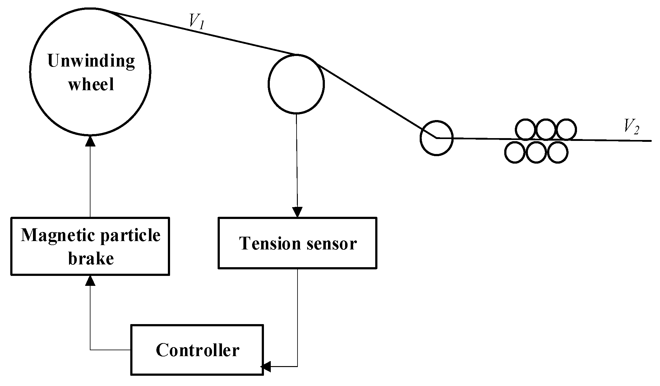
The tension control system of the winding machine unwinding mechanism consists of an actuating unit, a detection unit, and a traction unit. During operation, the magnetic powder brake connects to the wire bobbin to provide braking torque, while the traction motor supplies traction force via traction rollers, driving the wire bobbin for passive unwinding. During wire unwinding, the tension sensor monitors system tension in real time and transmits this to the controller. The controller compares the measured tension with the setpoint value to determine the error, adjusts the excitation current accordingly, and drives the magnetic powder brake to eliminate the error, thereby achieving constant tension control. The unwinding system schematic is shown in Figure 3.
The unwinding system of the winding machine uses the traction force of the traction mechanism to overcome the braking resistance of the magnetic powder brake to achieve passive unwinding. During the unwinding process, as the wire is continuously paid out, the roll diameter decreases non-linearly, and the rotational inertia of the unwinding system also decreases. To maintain a constant line speed, the unwinding mechanism needs to maintain dynamic balance through angular velocity compensation. This multi-variable coupling leads to fluctuations in the wire tension. According to the production process requirements, the wire should maintain a constant tension during the unwinding process of the winding machine. Based on the schematic diagram of the unwinding control system, the dynamics of the unwinding system are analyzed, and a mathematical model of the unwinding system is constructed. The schematic diagram of the unwinding control system is shown in Figure 4.
Taking the unwinding system as the research object, a dynamic torque balance equation is established [28].
d d t J ω = F R t M t M f
In the formula, J is the combined rotational inertia of the bobbin and wire, ω is the angular velocity of the bobbin, F is the wire tension, R t is the roll diameter, M t is the torque transmitted by the magneto-rheological brake, and M f is the frictional torque of the bobbin.
When the winding machine is unwinding, according to viscous friction theory, the magnitude of viscous frictional torque is proportional to angular velocity. Consequently, the frictional torque is M f = β ω , where β denotes the friction damping coefficient.
M t = F R t d d t J ω β ω
From Equation (2), it can be seen that the unwinding tension system is a complex and variable time-varying coupled system. In Equation (2), the moment of inertia J is the sum of the moment of inertia of the spool and the moment of inertia of the wire material. The moment of inertia of the spool J 0 is a constant, and the moment of inertia of the wire material is J 1 . Then:
J = J 0 + J 1
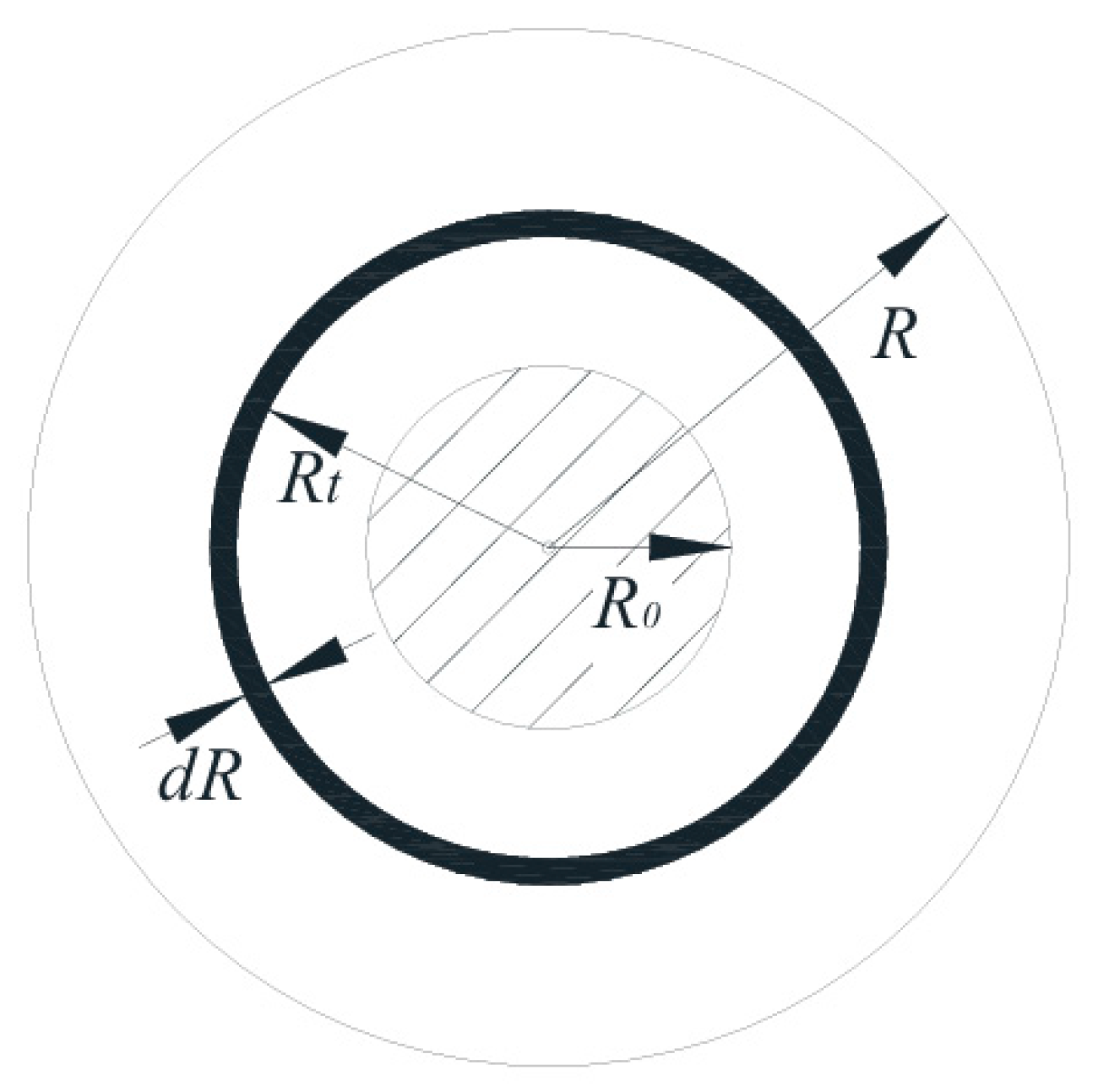
Assume that the wire is evenly wound on the bobbin. Suppose the unwinding wheel is cut radially to obtain the circular surface as shown in Figure 5. The black circular surface in the figure represents the cross-section of the wire. Supposing the mass density of the circular ring surface is ρ and the radius of the bobbin is R 0 , calculate the moment of inertia of the circular ring surface as shown in Figure 5. Considering that there is a certain gap when the wire is wound on the unwinding wheel, we apply a filling coefficient of λ . Then the area of the circular ring surface is d s = 2 π R t d R , the mass is d m = 2 π H ρ λ R t d R , H is the inner spacing of the bobbin, and D t is the diameter corresponding to the roll diameter R t . Then:
J 1 = R 0 R t 2 π H ρ λ R t 3 d R = 1 2 π H ρ λ R t 4 R 0 4
d J d t = d J 1 d t = 1 8 π ρ H D t 3 d D t d t
Let the angle through which the spool rotates within time t be φ and the unwinding angular velocity of the spool be v . Then the angular velocity of the spool is:
ω = v R t = d φ d t
Take the derivative of Equation (6):
d ω d t = 1 d t d v R t = 1 R t d v d t v R t 2 d R t d t = 1 R t d v d t v R t 2 d φ d t d R t d φ
For each rotation of the spool wheel, the length of the wire wrapped around the spool wheel decreases by one wire diameter d 0 . Then:
Δ R Δ φ = d 0 2 m π
where m represents the number of turns per layer of the wire, and “-” indicates that the winding diameter decreases as the rotation angle increases. By taking the limit of Equation (8), it can be obtained that:
d R d φ = d 0 2 m π
It can be obtained from Equations (6)–(9):
d ω d t = 1 R t d v d t + v 2 d 0 2 π m R t 3
The instantaneous change occurs over an extremely short period. During this period, the winding diameter is constant, and the moment of inertia is therefore also constant. Combined with Equation (5), Equation (2) can be simplified as:
M t = F R t J d ω d t β ω
Synthesizing Equations (3)–(11), the dynamic relationship expression is obtained during the unwinding process:
M t = F R t J 0 + 1 2 π B ρ λ R t 4 R 0 4 1 R t d v d t + v 2 d 0 2 π m R t 3 β v R t
Then the expression of tension is:
F = M t R t + J 0 + 1 2 π B ρ λ R t 4 R 0 4 1 R t 2 d v d t + v 2 d 0 2 π m R t 4 + β v R t 2
Therefore, Equation (13) indicates that for beryllium copper alloy wires with diameters ranging from 0.1 to 0.8 mm, the unwinding tension is influenced by roll diameter, unwinding speed, and rotational inertia during wire payout. Further analysis of actual production reveals that dynamic variations in unwinding speed and rotational inertia fundamentally originate from changes in roll diameter. Under operational conditions, the wire diameter ( d 0 = 0.1 mm) is negligible compared to the unwinding drum diameter, resulting in gradual diameter variation. During stable operation, the unwinding speed remains essentially constant. Consequently, the impact of rotational inertia and unwinding speed variations on tension is significantly less pronounced than that of roll diameter changes. Thus, roll diameter variation constitutes the primary cause of tension fluctuations. In the unwinding system, the controller dynamically regulates the excitation current in the magneto-rheological brake based on real-time roll diameter measurements. This compensates for tension variations and suppresses fluctuations induced by diameter attenuation, achieving dynamic constant-tension control.

4. Fuzzy PID Control Strategy Design and Simulation Verification

The fuzzy PID control algorithm applies fuzzy mathematics theory, emulating human cognitive and decision-making processes for complex problem solving. Based on expert experience, this intelligent control method integrates fuzzy logic with conventional PID control, constituting a human-like intelligent algorithm [29,30]. It expresses fuzzy logic through computational linguistic variables, introduces membership degrees to characterize linguistic uncertainty, and ultimately processes system nonlinearities and uncertainties through computational operations.
As shown in Figure 6, in the fuzzy PID control system for unwinding tension of the winding machine, the tension sensor measures output tension in real time. The deviation e and deviation change rate ec between ideal and measured tension values are calculated, with these values input to the fuzzy controller to obtain three gain values: Δ K P , Δ K I , and Δ K D . The PID controller adjusts parameters k p , k i , and k d based on these gains and initial setpoints. The tuned parameters regulate system tension to achieve constant-tension control in the unwinding system. The relationship between gains, initial setpoints, and PID parameters is given by the equation, where K P 1 , K I 1 , and K D 1 denote initial setpoints.
k p = K P 1 + Δ K P k i = K I 1 + Δ K I k d = K D 1 + Δ K D

4.1. Design of Fuzzy PID Control Strategy

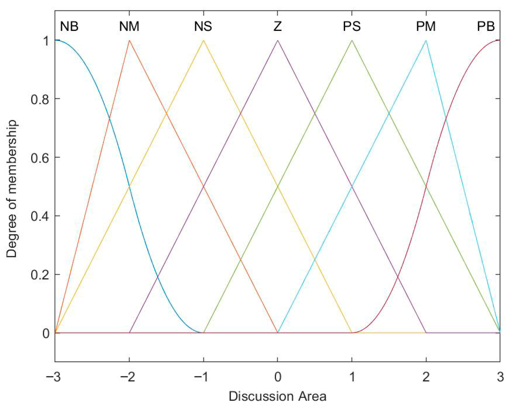
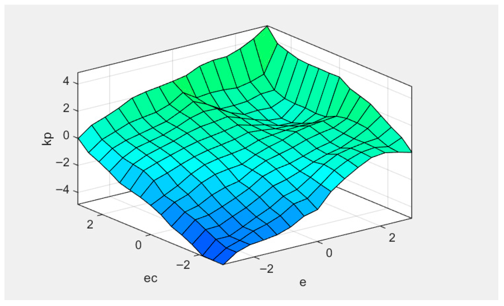
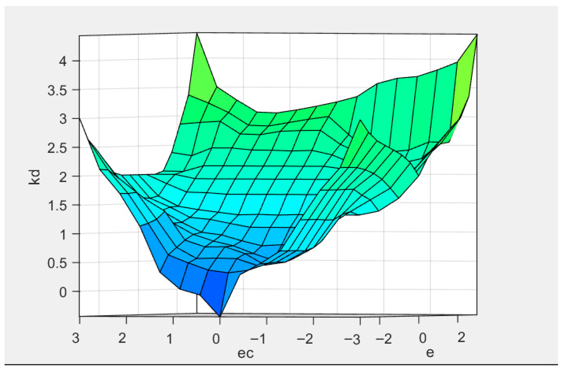
In the constant-tension fuzzy control system of the unwinding machine, a multi-variable fuzzy controller with dual inputs and triple outputs is designed. The inputs are tension deviation e and deviation change rate ec, while the outputs are parameters k p , k i , and k d . The fuzzy universes for e and ec are defined as 3 , + 3 . Given the basic fuzzy universe of 2 , + 2 for deviations in the tension system, the quantization factors for e and ec equal 1.5. Fuzzy subsets for e and ec are designated as N B , N M , N S , Z , P S , P M , P B , with k p , k i , and k d having fuzzy universes of 6 , + 6 . Triangular (trimf), Z-shaped (zmf), and S-shaped (smf) membership functions are combined to enhance boundary smoothing and improve relational characterization. Figure 7 and Figure 8 show the membership function curves. Based on PID tuning experience, Table 2 presents the fuzzy control rules. When designing the fuzzy controller, considering that the Mamdani inference method has the advantages of being intuitive, conforming to the human thinking model, having strong and flexible rule expression capabilities, and being easy for knowledge acquisition and rule library establishment, it was selected to obtain the fuzzy set of the control quantity. The centroid method, which is widely used and relatively simple in calculation, was employed for the defuzzification operation to convert the fuzzy quantity into an exact quantity. The mapping relationship is shown in Figure 9, Figure 10 and Figure 11.

4.2. Simulation Analysis

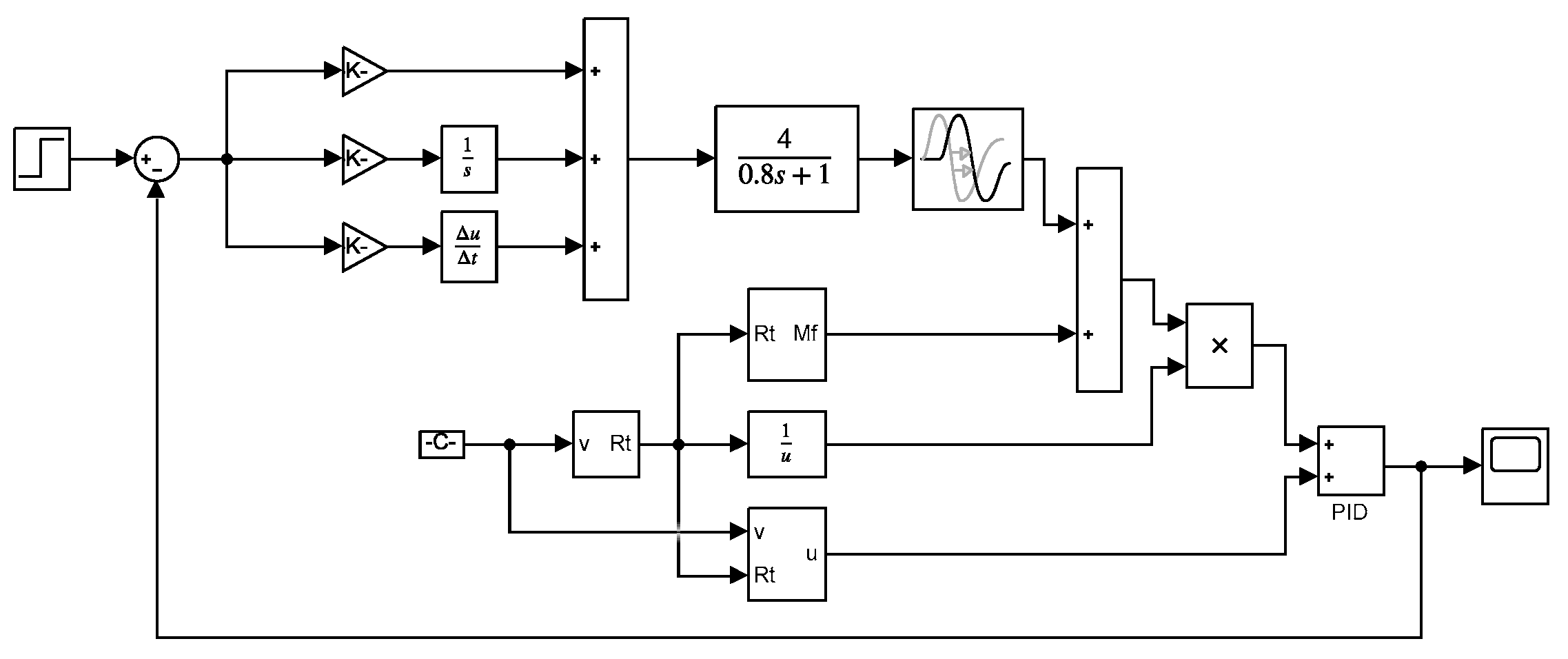
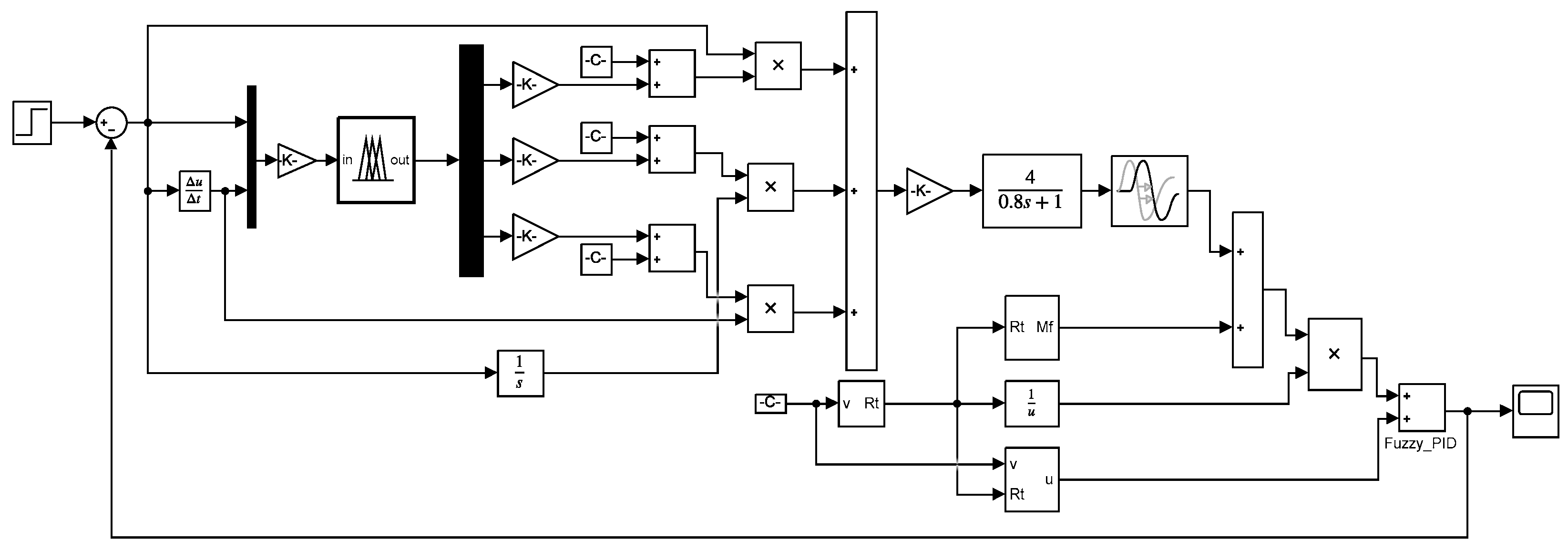
Based on the mathematical model established previously, conventional PID and fuzzy PID constant-tension control simulation models are built in Simulink. The magnetic powder brake is approximated by a first-order inertial link. Considering the delay process in magnetic particle chain formation, the brake’s hysteresis characteristics require adding a delay module in the simulation model [32]. The system’s input signal is a step response, with waveforms displayed on an oscilloscope. Relevant unwinding system parameters are listed in Table 3, and simulation block diagrams are shown in Figure 12 and Figure 13.
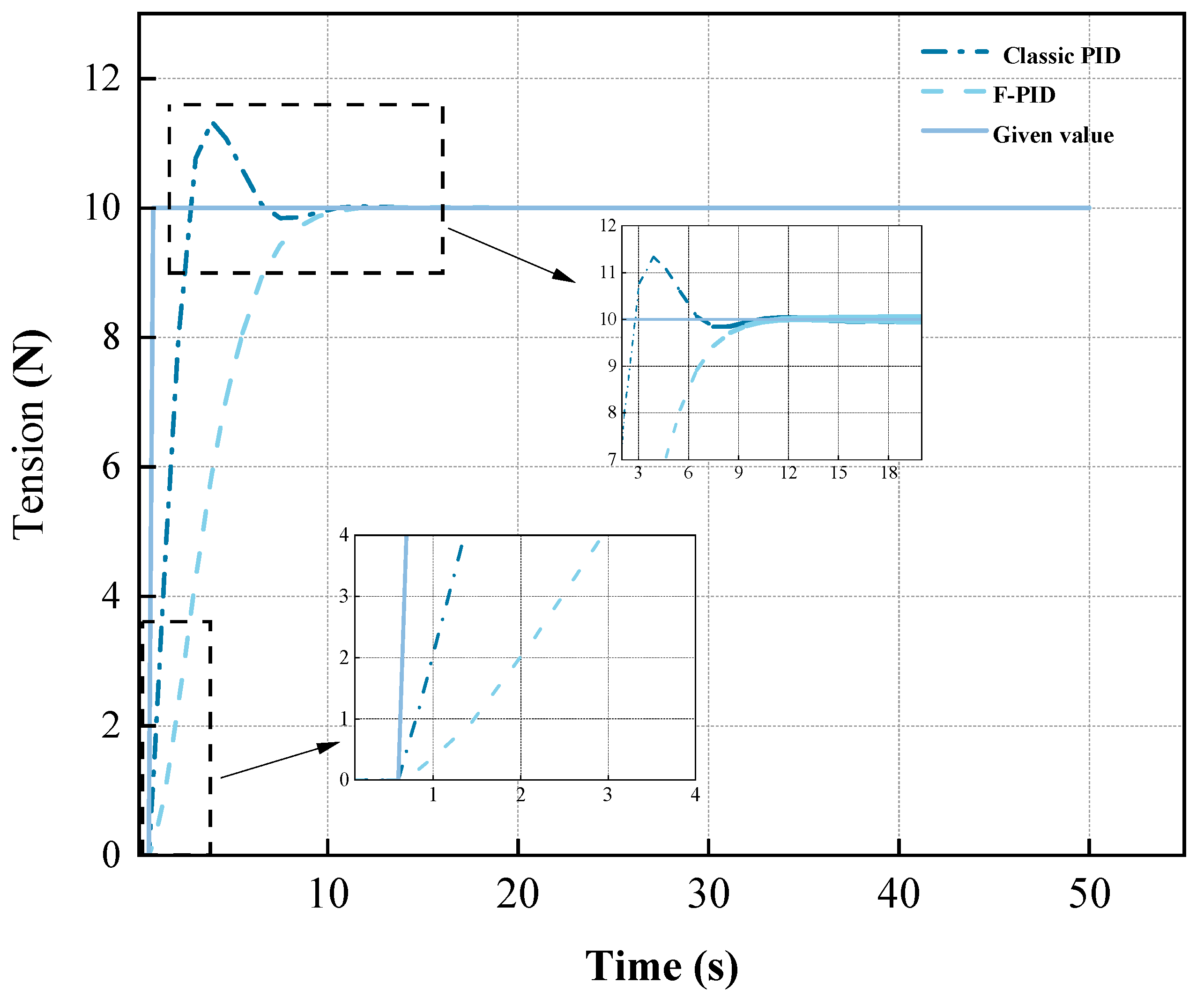
After substituting relevant parameters into the simulation model using a 50 s sampling time, the unwinding tension control simulation results for the winding machine are obtained as shown in Figure 14.
The system response curves indicate that both control strategies achieve stable states. For conventional PID control, maximum tension is 11.3 N with 13% overshoot and 15.5 s stabilization time. In the fuzzy PID control system, the system directly reaches the ideal value, and the stabilization time is 12.5 s, which is 3 s faster than that of the conventional PID control, and the system does not have overshoot. Comparative analysis shows fuzzy control significantly reduces overshoot and achieves faster stabilization, though with marginally slower initial response than conventional PID.
During control system operation, external disturbances may occur, affecting accuracy and stability. Thus, simulation experiments must incorporate disturbance scenarios to verify system performance metrics [33].
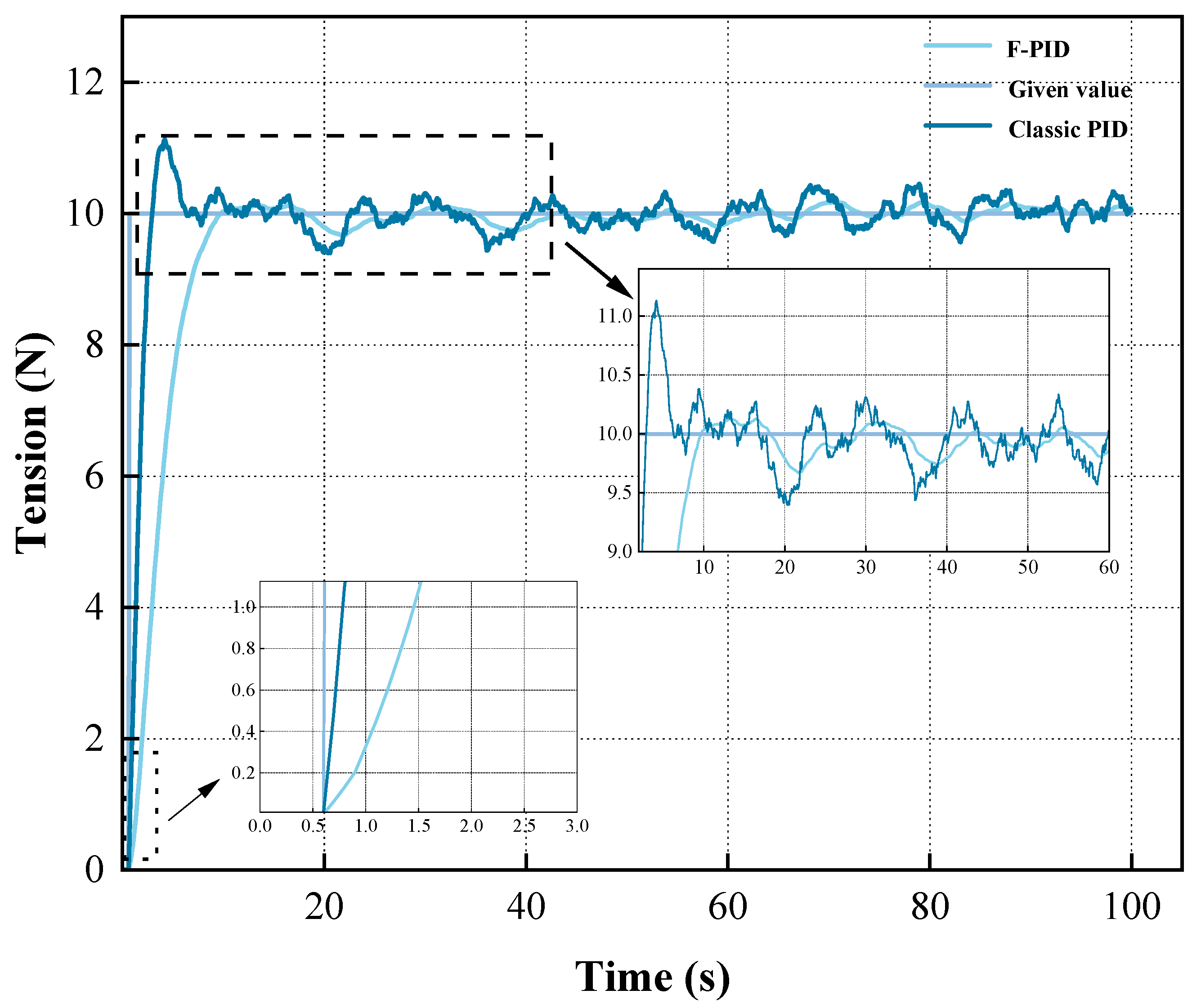
During winding machine operation, external disturbances such as machine vibration and working noise may compromise control precision, causing non-uniform stress distribution across wire cross-sections during coiling and compromising product quality [34]. White noise with a normalized power of 0.1 at a 0.1 s sampling period serves as the external disturbance signal. Comparative analysis of both control strategies verifies system stability and disturbance rejection capability, with response curves under disturbance shown in Figure 15.
Figure 15 clearly demonstrates that under conventional PID control with external disturbances, the response exhibits significant overshoot and poor disturbance rejection. Throughout the sampling period, the curve fluctuates widely around the ideal tension value, indicating compromised system stability. In contrast, the fuzzy PID response shows zero overshoot with low-frequency fluctuations confined near the ideal tension value. The fluctuation amplitude remains minimal at ± 0.128   N (1.28% error). Comparative analysis confirms the fuzzy PID strategy’s superior control performance and enhanced disturbance rejection in the constant-tension system, effectively maintaining stability and demonstrating strong robustness under external disturbances.
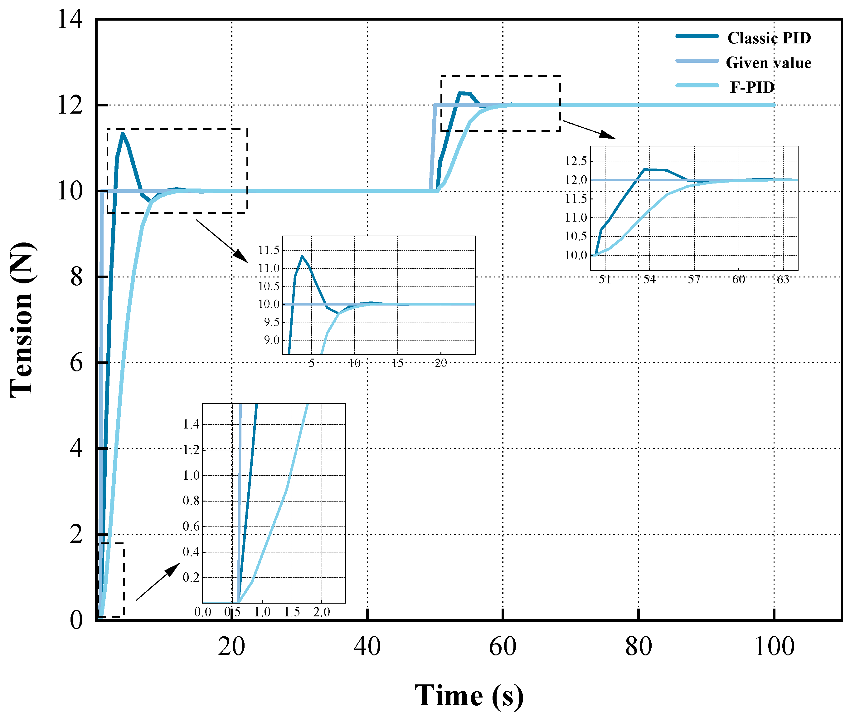
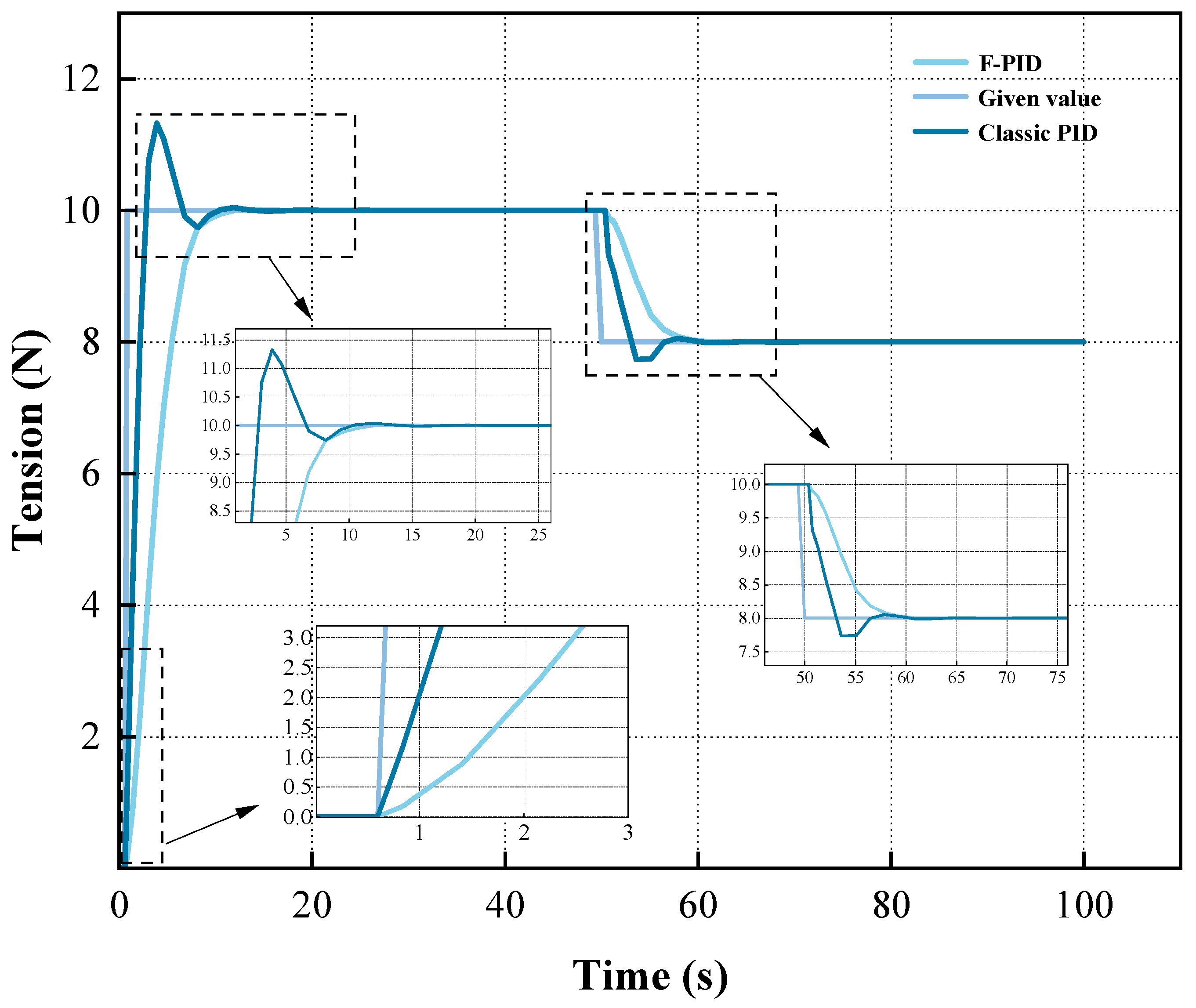
During winding machine operation, tension transients may occur due to process parameter variations. Thus, simulation experiments must replicate system behavior during abrupt tension changes. The simulation parameters include a 100 s total sampling time, with a 2 N tension step input introduced at 50 s to simulate setpoint switching. This section simulates tension transients from 10-12 N and 10-8 N under both conventional and fuzzy PID control strategies, as shown in Figure 16 and Figure 17.
From Figure 16 and Figure 17, it is observed that when the tension value undergoes a step change, both the conventional PID control strategy and the fuzzy PID control strategy enable the system to reach a stable state following a brief transient adjustment, achieving the ideal tension value with no steady-state error. From Figure 16 and Figure 17, the response results of conventional PID control and fuzzy PID control under the step-tension-change condition can be obtained. The specific results are shown in Table 4.
As can be seen from Table 4, in response to step tension disturbances, the fuzzy PID tension control system exhibits a shorter settling time compared to the conventional PID system and exhibits no overshoot. This indicates that the fuzzy PID control strategy can effectively cope with sudden changes in system load, significantly reducing the risk of line breakage caused by overshoot, which verifies the applicability of this algorithm in complex industrial scenarios.

5. Conclusions

This study addresses insufficient tension control accuracy in winding machines by designing an unwinding mechanism and establishing a coupled model relating unwinding tension to roll diameter, payout speed, and rotational inertia. Practical production analysis identifies roll diameter variation as the primary cause of tension fluctuations. Accordingly, a fuzzy PID constant-tension control strategy is developed, incorporating application-specific scenarios with a tailored fuzzy rule base. Unlike conventional empirical rule transplantation in fuzzy PID systems, this rule set is systematically refined through in-depth analysis of nonlinear tension characteristics and dynamic load response patterns during winding. Conventional PID and fuzzy PID control models are implemented on 2020 MATLAB/Simulink for performance validation. Simulation tests under practical conditions—including abrupt tension changes and noise disturbances—demonstrate superior control performance of the production-experience-integrated fuzzy PID strategy in time-varying, multi-coupled nonlinear unwinding systems. Notably, the fuzzy PID controller exhibits enhanced disturbance rejection, confining tension fluctuations within narrower ranges during noise interference and sudden tension variations. This strategy significantly improves tension control stability and robustness, overcoming conventional PID’s limitations in time-varying systems. Although the automatic winding machine design achieves constant-tension control, only primary influencing factors of tension fluctuations were considered. Future research should incorporate secondary factors to establish more precise mathematical models. Furthermore, as intelligent control algorithms evolve, current methods reveal theoretical constraints in real-time dynamic parameter identification, high-dimensional state-space search efficiency, and multi-objective optimization. Subsequent studies could integrate autonomous learning-capable intelligent control architectures to enhance precision and disturbance immunity.

Author Contributions

Conceptualization, P.H. and W.W.; methodology, Z.L.; software, P.H.; validation, P.H. and J.P.; formal analysis, P.H.; investigation, P.H. and J.P.; resources, W.Z.; data curation, P.H. and J.P.; writing—original draft preparation, P.H.; writing—review and editing, W.W.; visualization, Z.L. and W.Z.; supervision, Z.L. and W.Z.; project administration, W.W.; funding acquisition, W.W. All authors have read and agreed to the published version of the manuscript.

Funding

Baoji University of Arts and Sciences Graduate Innovation and Entrepreneurship Project: YJSCX24YB61.

Data Availability Statement

The original contributions presented in this study are included in the article. Further inquiries can be directed to the corresponding author.

Conflicts of Interest

The authors declare no conflicts of interest.

References

  1. Ghate, M.; Pradhan, S.; Patel, M.; Bhavsar, D.; Vasava, K. Design and Fabrication of a Special Purpose Winding Machine for ELM Control Coils of JET. IEEE Trans. Appl. Supercond. 2016, 26, 0602704. [Google Scholar] [CrossRef]
  2. Mohammad, I.B.; Zahra, N.G.; Farid, T. Modeling, Performance Analyzing, and Prototyping of Variable Reluctance Resolver with Toroidal Winding. IEEE Sens. J. 2021, 21, 4425–4432. [Google Scholar] [CrossRef]
  3. Lin, H.C.; Peng, Y.H.; Xu, H.J.; Xu, Z.-X. Achievement of automatic nylon rope winding control using adaptive decision-making algorithm. Int. J. Adv. Manuf. Technol. 2024, 135, 1865–1876. [Google Scholar] [CrossRef]
  4. Zhang, Y.S.; Ma, H.W.; Wang, H.T. Research on speed regulation method of winding machine based on rectangular line mode. IOP Conf. Ser. Mater. Sci. Eng. 2019, 668, 12023. [Google Scholar] [CrossRef]
  5. Deng, L.W.; Suo, H.F.; Ren, H.N. Design of Insulation Tape Tension Control System of Transformer Winding Machine Based on Fuzzy PID. Sensors 2021, 21, 6512. [Google Scholar] [CrossRef]
  6. Xu, X.M.; Zhang, W.X.; Ding, X.L.; Zhang, M.; Wei, S.-H. Design and Analysis of a Novel Tension Control Method for Winding Machine. Chin. J. Mech. Eng. 2018, 31, 101. [Google Scholar] [CrossRef]
  7. Asano, K.; Motomura, T. Robust Decentralized Tension Control in Hot Rolling. IFAC Pap. Line 2009, 42, 249–254. [Google Scholar] [CrossRef]
  8. Lu, J.S.; Cheng, M.Y.; Su, K.H. Wire tension control of an automatic motor winding machine—An iterative learning sliding mode control approach. Robot. Comput.-Integr. Manuf. 2018, 50, 50–62. [Google Scholar] [CrossRef]
  9. Wang, G.; Gao, Y.; Ding, J.; Sun, J. Study on High-Precision Tension Control Technology for a Cold-Rolling Pilot Mill with Hydraulic Tension. Appl. Sci. 2024, 14, 877. [Google Scholar] [CrossRef]
  10. Li, G.P.; Yan, F.G.; Wang, C. Research on the Simulation of Tension Control System of the Traction Wire Rope Cleaning and Detection Line of Pay-Off Unit. Appl. Mech. Mater. 2014, 3485, 1451–1456. [Google Scholar] [CrossRef]
  11. Cheng, G.Y.; Wang, D.Y.; Sun, M.; Fu, Z.; Yuan, B.; Zhang, L.; Xiao, X. Optimizing Subway Train Operation with Hierarchical Adaptive Control Approach. IEEE Access 2023, 11, 138292–138302. [Google Scholar] [CrossRef]
  12. Meng, F.W.; Liu, S.; Liu, K. Design of an Optimal Fractional Order PID for Constant Tension Control System. IEEE Access 2020, 8, 58933–58939. [Google Scholar] [CrossRef]
  13. Ahn, B.J.; Choi, J.Y.; Chang, Y.S.; Lee, M.H. On the full stand modeling and tension control for the hot strip finishing mill with PID structure. KSME Int. J. 2004, 18, 1062–1073. [Google Scholar] [CrossRef]
  14. Ju, G.; Liu, S.; Feng, L.; Wang, C.; Yang, K. Modeling of Accumulator in Roll-to-Roll Coating Equipment and Tension Control with Nonlinear PID. Polymers 2024, 16, 3479. [Google Scholar] [CrossRef]
  15. Li, Q.; Bai, J.; Fan, Y.; Zhang, Z. Study of wire tension control system based on closed loop PID control in HS-WEDM. Int. J. Adv. Manuf. Technol. 2016, 82, 1089–1097. [Google Scholar] [CrossRef]
  16. Cheng, L.; Zheng, C.G.; Li, Y.; Chen, C.; Zhang, S.; Wu, J.; Dong, H.; Ke, Y. Fiber tension prediction and control methods in automated fiber placement. Polym. Compos. 2024, 45, 14888–14904. [Google Scholar] [CrossRef]
  17. Thiffautt, C.; Sicard, P.; Bouscayrol, A. Tension control loop using a linear actuator based on the energetic macroscopic representation. Electr. Comput. Eng. 2004, 4, 2041–2046. [Google Scholar] [CrossRef]
  18. Huang, J.; Gao, M.; He, Z. The application of PID controller with dead zone for yarn’s constant tension control system. In Proceedings of the 2013 IEEE 8th Conference on Industrial Electronics and Applications (ICIEA), Melbourne, VIC, Australia, 19–21 June 2013; pp. 348–351. [Google Scholar] [CrossRef]
  19. Gu, Z.W.; Zeng, S.K.; Zhao, J. Fully-digital tension control system with PID algorithm for winding ultra-fine enameled wires. IOP Conf. Ser. Mater. Sci. Eng. 2020, 892, 12064. [Google Scholar] [CrossRef]
  20. Ding, Y.W. Comparative study on control effect of permanent magnet synchronous motor based on Fuzzy PID control and BP neural network PID control. J. Phys. Conf. Ser. 2021, 1802, 32080. [Google Scholar] [CrossRef]
  21. Xiao, Y.; Zhang, Z.; Liu, Z.; Zhang, Z.; Zhou, W.; Liu, W. Research on integral separation control of warp tension based on fuzzy parameter optimization. J. Intell. Fuzzy Syst. 2021, 41, 3031–3044. [Google Scholar] [CrossRef]
  22. Zheng, B.P. Design of yarn tension self-adaptive control system on warp knitting machine. J. Text. Inst. 2023, 115, 173–187. [Google Scholar] [CrossRef]
  23. Tu, L.; Guo, M.R.; Wang, J.G.; Gao, W. Warp yarn tension coupling models and fuzzy PID control for enhancing warp beam unwinding tension stability in sizing machines. J. Ind. Text. 2024, 2024, 32. [Google Scholar] [CrossRef]
  24. Liu, W.; Wu, X.; Du, X.; Xu, G.; Wang, S. Tension Networked Control Strategy for Carbon Fiber Multilayer Diagonal Loom. IEEE Access 2020, 8, 32280–32289. [Google Scholar] [CrossRef]
  25. Li, Y.; Wu, S.; Liu, C.; Lu, Q.; Chen, J.; Yan, J.; Yue, Q. Modelling and control of tension in a flexible pipe tensile armour manufacturing process. Int. J. Adv. Manuf. Technol. 2024, 133, 3927–3936. [Google Scholar] [CrossRef]
  26. Ai, Y.; Yu, B.; Zhang, Y.; Xu, W.; Lu, T. Constant Tension Control System of High-Voltage Coil Winding Machine Based on Smith Predictor-Optimized Active Disturbance Rejection Control Algorithm. Sensors 2023, 23, 140. [Google Scholar] [CrossRef]
  27. Delis, J.S. Design considerations, machinery and control options in coil winding. IEEE Electr. Insul. Mag. 1993, 9, 16–22. [Google Scholar] [CrossRef]
  28. Su, H.; Zhang, X. On the Mechanical Analysis and Control for the Tension System of the Cylindrical Filament Winding. J. Text. Sci. Technol. 2016, 2, 7–15. [Google Scholar] [CrossRef]
  29. Zhou, Q.C.; Wang, K.X.; Xiong, L.; Zhao, J. Optimization of Bridge Crane Control System Using Fuzzy PID Control and Speed Control of Frequency Converter. J. Phys. Conf. Ser. 2021, 1802, 032007. [Google Scholar] [CrossRef]
  30. Hou, G.X.; Wang, L.C. Induction Heating Furnace Temperature Control Based on the Fuzzy PID. Appl. Mech. Mater. 2012, 2024, 2463–2466. [Google Scholar] [CrossRef]
  31. Xu, J. End Effector Control System of 6R Manipulator Based on Fuzzy PID. Highlights Sci. Eng. Technol. 2022, 7, 332–345. [Google Scholar] [CrossRef]
  32. Chunxiang, W.; Ruqing, Y.; Yongzhang, W.; Hua, L. Research on a precision tension control system with a magnetic particle clutch as the actuator. Int. J. Adv. Manuf. Technol. 2005, 27, 7–13. [Google Scholar] [CrossRef]
  33. Mi, J.J.; Yao, J.Y.; Deng, W.X. Adaptive RISE Control of Winding Tension with Active Disturbance Rejection. Chin. J. Mech. Eng. 2024, 37, 52. [Google Scholar] [CrossRef]
  34. He, K.; Liu, S.; Wang, K.; Mei, X. Thermal Characteristics of Plastic Film Tension in Roll-to-Roll Gravure Printed Electronics. Appl. Sci. 2018, 8, 312. [Google Scholar] [CrossRef]
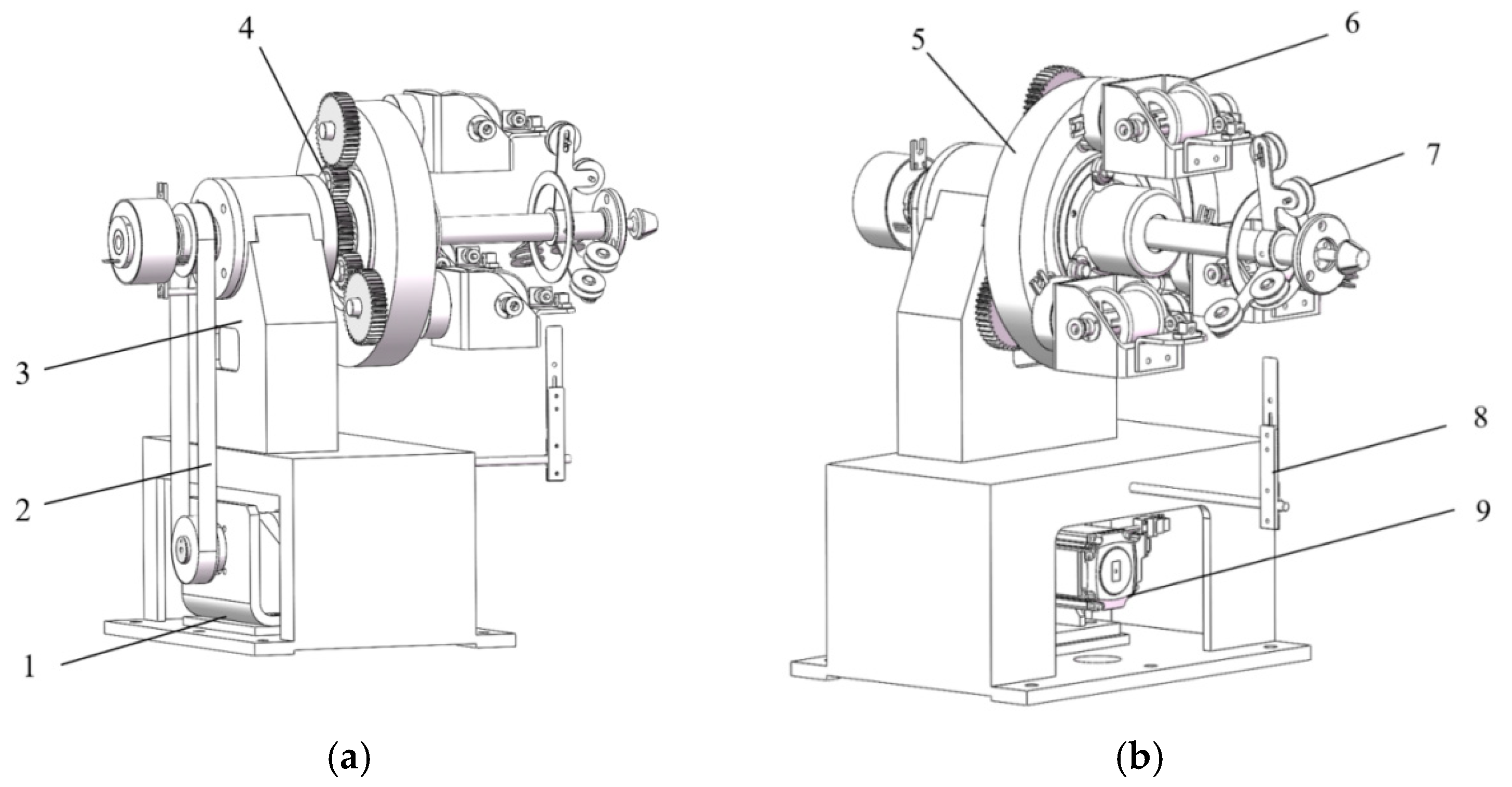
Figure 1. Schematic diagram of constant tension unwinding mechanism for winding machine: (a) Schematic diagram of the back side of the unwinding mechanism of the winding machine. (b) Schematic diagram of the front side of the unwinding mechanism of the winding machine. (1) Motor mount, (2) synchronous belt, (3) stranding machine base, (4) swivel wheel system, (5) turntable, (6) shuttle frame, (7) guide ring, (8) stop lever, (9) servo motor.
Processes 13 02612 g001
Figure 2. Schematic diagram of shuttle frame mechanism. (1) Curved plate, (2) cable pay off wheel, (3) magnetic particle brake, (4) tension sensor, (5) ceramic pipe.
Processes 13 02612 g002
Figure 3. Schematic diagram of unwinding system.
Processes 13 02612 g003
Figure 4. Simplified schematic diagram of unwinding control system.
Processes 13 02612 g004
Figure 5. Wire winding model.
Processes 13 02612 g005
Figure 6. Schematic diagram of fuzzy PID control principle.
Processes 13 02612 g006
Figure 7. Membership function curves of e and ec.
Processes 13 02612 g007
Figure 8. Membership function curves of kp, ki, and kd.
Processes 13 02612 g008
Figure 9. Mapping relationship between kp, e, and ec.
Processes 13 02612 g009
Figure 10. Mapping relationship between ki, e, and ec.
Processes 13 02612 g010
Figure 11. Mapping relationship between kd, e, and ec.
Processes 13 02612 g011
Figure 12. Standard PID simulation model.
Processes 13 02612 g012
Figure 13. Fuzzy PID simulation model.
Processes 13 02612 g013
Figure 14. Response curves of PID and FPID.
Processes 13 02612 g014
Figure 15. Response curves of conventional PID control and fuzzy PID control under external disturbances.
Processes 13 02612 g015
Figure 16. Response curves of conventional PID and fuzzy PID control under sudden tension change of 10-12 N.
Processes 13 02612 g016
Figure 17. Response curves of conventional PID and fuzzy PID control under sudden tension change of 10-8 N.
Processes 13 02612 g017
Table 1. Parameter requirements for automatic winding machines.
Equipment CharacteristicsParameters
Payoff Wheel Specifications Φ 78 × Φ 36 × Φ 10 × 70 × 50 mm
Equipment Weight500 kg
Electric Power SourceAC 380 V
Product Qualification Rate96%
Number of Revolutions Per Minute100–400 rpm
Traction Line Speed50–800 mm/min
Static≤80 decibel
Power0.75 kW
Table 2. Fuzzy rule table [31].
ec
eNB/Z/PSNB/Z/NSNB/Z/NBNM/Z/NBNS/Z/NBNS/Z/NMZ/Z/PS
NB/NM/PSNB/NM/NSNM/NS/NBNS/NS/NMNS/NS/NMZ/Z/NSPS/Z/Z
NM/NB/ZNM/NM/NSNM/NS/NMNS/NS/NMZ/Z/NSPS/PS/NSPS/PS/Z
NM/NB/ZNM/NM/NSNS/NS/NSZ/Z/NSPS/PS/NSPM/PM/NSPM/PB/Z
NS/NS/ZNS/NS/ZZ/Z/ZPS/PS/ZPS/PS/ZPM/PM/ZPM/PB/Z
NS/Z/PBZ/Z/NSPS/PS/PSPM/PS/PSNM/PS/PSPM/PS/PSPB/PM/PB
Z/Z/PBPS/Z/PMPM/Z/PMPM/Z/PMPM/Z/PSPM/Z/PSPB/Z/PB
Table 3. Technical specifications for winding machine simulation.
Parameter NameParameter Value
Tension Ideal10 N
Wire Diameter0.1 mm
Wire Density8.3 g/cm3
Diameter of Payoff Wheel70 mm
Spacing Inside the Wire Bobbin Wheel50 mm
Wire Bobbin Quality0.3 kg
Packing Factor0.785
Weight of a Coil of Wire1.016 kg
Table 4. Comparison of two control strategies under sudden tension change conditions.
Control MethodsPre-Mutation Stabilization TimeStabilization Time After MutationPre-Mutational OvershootThe Amount of Overshoot After Mutation
10-12 N PID13.57 s63.10 s13%2.25%
10-12 N F-PID10.53 s61.22 s00
10-8 N PID13.56 s64.74 s13%16.5%
10-8 N F-PID10.52 s60.96 s00
Disclaimer/Publisher’s Note: The statements, opinions and data contained in all publications are solely those of the individual author(s) and contributor(s) and not of MDPI and/or the editor(s). MDPI and/or the editor(s) disclaim responsibility for any injury to people or property resulting from any ideas, methods, instructions or products referred to in the content.