Abstract
With the global transition towards renewable energy, pumped storage has become a pivotal technology for large-scale energy storage, playing an essential role in peak load regulation, frequency control, and ensuring the stability of modern power systems. As the core equipment of pumped storage power stations, pump-turbines operate under complex and frequently changing conditions. These units are required to switch repeatedly between pumping, generating, and transitional modes, giving rise to significant fluid–structure interactions (FSIs). Such interactions have a profound impact on the operational performance and stability of the units. This review provides a comprehensive summary of current research on FSIs in pump-turbines, encompassing both experimental investigations and numerical simulations. Key topics discussed include internal flow dynamics, vibration and acoustic characteristics, and structural responses such as runner deformation and stress distribution. Various numerical coupling strategies for FSI modeling are also examined in detail. Despite progress in this field, several challenges remain, including the complexity of multidisciplinary coupling, the difficulty in developing and solving accurate models, and limitations in predictive capabilities. This review highlights the critical requirements for advancing FSI research in pump-turbines and identifies gaps in the current literature that warrant further investigation.
1. Introduction
The new energy revolution aims to construct a future energy system that can be sustained over the long term. A growing number of nations have turned to the advancement of new and renewable energy sources as a key strategy to ease energy supply tensions and tackle climate change. Among these, wind and solar power stand out due to their well-developed technologies and widespread commercial acceptance [1]. As of the close of 2023, wind and solar energy made up 98% of the newly added installed capacity for renewable energy. Since most renewable energy is harnessed cleanly by converting it into electricity, the power grid has grown increasingly crucial. It is set to become an indispensable network for energy transmission and distribution across society, thereby imposing more stringent demands on its safety, adaptability, and ability to optimize and allocate resources [2,3]. In general, renewable energy is marked by its variability, as it cannot sustain or adjust to provide a steady power output. This trait directly undermines the stability of power generation. Meanwhile, the gap between peak and off-peak periods in power systems is widening, which raises higher bars for the grid’s ability to regulate and resist interference. For this reason, large-scale energy storage solutions have become a necessity [4]. In particular, as unstable renewable energy sources such as wind and solar power expand rapidly, their integration into the power grid calls for backing from complementary energy storage systems. Herein, pumped storage power stations serve as an effective solution: they help narrow the peak–valley gap, mitigate the intermittent nature of renewable energy, and avoid voltage or frequency fluctuations—even blackouts—triggered by grid supply–demand imbalances. Additionally, they facilitate greater integration of clean energy like wind and solar photovoltaic power into the grid. Boasting a cycle efficiency of 75% to 85% and highly competitive costs, these stations play a vital role in the energy system [5]. Pumped storage units are currently the most technologically mature, lowest-cost, and largest-capacity grid-level energy storage technology, serving as a key component in building a new type of power system.
Pumped storage units are a type of hydraulic power generation equipment capable of flexibly switching between pumping and power generation modes [6]. When the grid is under low load, the units run in pumping mode, drawing on excess electricity to pump water from the lower reservoir to the upper one. In this process, electrical energy is converted into the potential energy stored in water. When the grid load reaches its peak, the units shift to turbine mode: water from the upper reservoir is released to generate electricity, thus supplementing the power supply. These units perform key functions in the power system, including peak shaving, valley filling, frequency regulation, and phase regulation, all of which are crucial for maintaining the stability of the power system. To cut down on manufacturing and construction costs while boosting the hydraulic efficiency of the units, a growing number of pump-turbines are being designed with larger unit capacities and higher hydraulic heads [7], as shown in Figure 1. As the operating water head rises, hydraulic instability issues like pressure fluctuations grow more intense. These can induce mechanical vibrations via fluid–structure interactions, and in extreme scenarios, may even result in premature mechanical breakdowns. Under partial load conditions, especially in pump operation mode, self-excited vibration phenomena may also occur. The interaction between the rotating and stationary parts of pump-turbines can give rise to high-amplitude dynamic pressures on the blades [8,9]. For instance, certain flow features like vortices in the draft tube and runner, along with rotor–stator interaction (RSI), will amplify pressure fluctuations, putting pumped hydroenergy storage (PHES) plants at greater risk of significant structural harm. When the number of fatigue cycles of pump-turbine blades exceeds the threshold limit, fatigue-induced cracks are prone to occur [10,11,12].
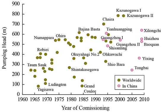
Figure 1.
Global PSPS hydraulic head development trend [7].
2. Pump-Turbine Flow Field Investigation
Pump-turbines need to alternate between pumping and turbine operations. with significantly different optimal operating points under different modes, leading to strong unsteady flows under partial load conditions (such as start-up, shutdown, and load regulation. Under partial load in pump mode, rotating stall and surge may be triggered, while during transitional states in turbine mode, eccentric vortex ropes tend to form in the draft tube. These generate low-frequency pressure fluctuations, which can induce unit vibrations or even resonance. Under these operating conditions, prominent issues include deteriorated flow patterns [13,14], reduced efficiency [15,16], intensified pressure pulsations [17,18,19], and flow-induced vibrations of the unit [20,21], which frequently lead to unstable power station operations or even accidents. These phenomena can be summarized into three categories: efficiency issues, stability issues, and cavitation problems.
First, when the unit operates at partial load deviating from the design condition, its efficiency may significantly decline. For instance, under low-load conditions, issues like backflow and vortices can emerge in parts such as the runner and guide vanes, which impairs the efficiency of energy conversion. In an accident investigation of a certain unit, Egusquiza et al. [22] found that pressure pulsations in the vaneless zone under off-design conditions directly caused runner damage. Traditional pump-turbine runners are usually designed with a focus on efficiency and stability around the design point, which makes it difficult to meet the requirements of a broad power output range. Thus, developing pump-turbines that feature high efficiency, low cavitation, and a wide operating range has become an urgent task. For many large-scale pump-turbines (with capacities exceeding 100 MW), even a slight improvement in efficiency can yield substantial economic gains [23]. Current research on efficiency issues focuses on designing runners with excellent comprehensive performance. Beyond optimizing the hydraulic structure, minimizing flow energy dissipation (FED) in pump-turbines is vital for enhancing the energy conversion efficiency of pumped storage power stations. However, further improving efficiency still faces challenges due to the difficulty in visualizing, locating, and quantifying flow energy dissipation [24,25].
Second, regarding stability issues, pump-turbines may enter the S-characteristic region during transient processes such as load rejection, as shown in Figure 2. In this state, the unit’s operating conditions fluctuate violently: multiple flow values may correspond to the same rotational speed, pressure pulsations intensify, and there is even a risk of mechanical damage. This S-shaped characteristic exacerbates instability during related transient processes [26], such as power fluctuations and difficulties in synchronizing with the grid during grid-connected operation. Staubli et al. [27] studied the internal flow field of pump-turbines in the S-characteristic region and verified the existence of unstable phenomena. Generally, when grid parameter fluctuations exceed the controllable range, the pump-turbine’s generator automatically disconnects from the grid, leading to load rejection. Tanaka et al. [28] and Huang et al. [29] recorded the phenomenon of unstable reciprocating surging in the draft tube during load rejection, as illustrated in Figure 3. Research shows that under extreme conditions, the pressure in the draft tube can reach a vacuum, leading to harmful water column separation. Should the guide vanes fail to close promptly after load rejection, the unit will go into a runaway state. The S-shaped characteristics of pump-turbines frequently induce self-excited oscillations during runaway conditions [17]. Fluctuations in operational parameters, including torque, pressure and rotational speed, cannot converge to the constant values typically found in conventional Francis turbines, resulting in drastically intensified vibrations, shortened runner life, and even rotor damage. Many studies have shown that when pump-turbines are in the runaway process, various flow patterns form and develop in the flow passage [30].
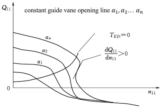
Figure 2.
The S-curve characteristics of a pump-turbine.
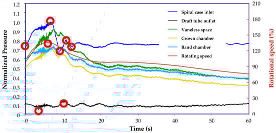
Figure 3.
Instance of reciprocating surges occurring in the manifold part of the penstock [29].
As a pump-turbine’s operating conditions shift along its S-shaped characteristic curve, rotating stall can lead to blockages and backflow in the flow passages. This results in severe fluctuations in the unit’s flow rate and rotational speed, causing its operating point to oscillate repeatedly between turbine mode, turbine braking mode, and reverse pump mode. Such behavior not only renders stable operation and grid-connected power generation unachievable but also induces resonance in components like guide vanes and spiral casings. In a visualization study on the internal flow field of pump-turbines, Hasmatuchi et al. [31] and Li et al. [32] observed that besides the presence of a rotating stall cell in the runner passage, low-frequency signals associated with rotating stall were also distinctly detectable in the vaneless zone and guide vane zone, as depicted in Figure 4. Pacot [30] observed that under the impact of the stall cell, the flow passage became blocked, and the fluid pressure in certain flow passages dropped. This pressure reduction was particularly pronounced in the vaneless zone, which created more conducive conditions for backflow.
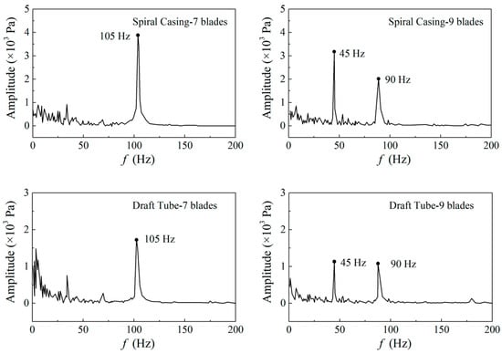
Figure 4.
Frequency spectrums of pressure fluctuations in the spiral casing and draft tube [32].
When the unit operates in the hump zone of the pump mode, severe hydraulic vibrations occur in the flow passage, even causing serious damage to the flow components. Hump zone instability is currently a major issue affecting the safe operation of the unit. Sinha et al. [33] and Sano et al. [34] first turned their research attention to the hump zone, emphasizing the influence of the runner and radial clearance on the development of internal flow instability characteristics of the unit. Ciocan [35] first studied the hump characteristics of pump-turbines and discovered the phenomenon of water flow blockage in the guide vane area. Braun et al. [36] found that when the unit enters the hump zone, strong vortices exist between the two rows of cascades, and the flow conditions in the flow passage are extremely poor. In general, the instability of hump characteristics is mainly related to factors such as vortices [37,38,39], suction surface cavitation [40], runner inlet backflow [41], pre-rotation, recirculation [42], rotating stall [43,44,45], and vortex motion in stay vanes [46].
2.1. Experimental Techniques
In terms of experimental techniques, advanced equipment was used to accurately acquire experimental information, as shown in Figure 5. The application of Laser Doppler Anemometry (LDA) [47,48], dynamic pressure sensors, Particle Image Velocimetry (PIV) [49,50,51], and LDV [52,53] has improved the accuracy of experimental data acquisition. These techniques can capture high-speed motion details in the flow field without disturbing the water flow, providing a reliable basis for theoretical analysis. For example, PIV was used to analyze the flow field in the guide vane area of a low-specific-speed pump-turbine during pumping mode. Transient flow measurements uncovered the spatiotemporal development of the rotating stall within the guide vane passages, such as the onset of flow separation, the spread of stall cells, and the resulting mechanisms behind pressure pulsations. Furthermore, Laser Doppler Velocimetry (LDV) was applied to measure the velocity at the runner outlet, encompassing axial and circumferential velocity tests under various operating conditions [53]. At present, more experimental studies aim to obtain the unit’s performance curves [54] and validate the prediction methods for flow rate (Q)-head (H) curves [55,56]. Tests are typically conducted on parameters such as energy efficiency, cavitation, pressure fluctuations, runaway characteristics, full four-quadrant characteristics, pump hump margin, zero flow in pump mode, guide vane hydrodynamic torque, low heads in both pump and turbine modes and water thrust.
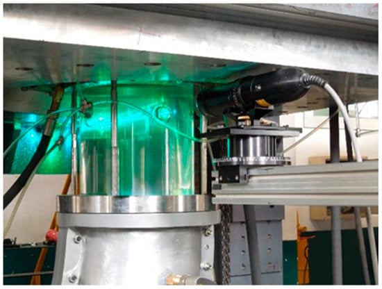
Figure 5.
Experimental methods for flow field analysis of pump-turbines [52].
2.2. Numerical Simulation
In comparison to physical experiments, Computational Fluid Dynamics (CFD) numerical analysis boasts notable benefits in aspects such as cost, cycle duration, and the quantity of information acquired. Therefore, this method is becoming increasingly popular and can also serve as a reference for experimental data from LDA, PIV, and LDV. The S-shaped and hump regions are critical areas that cause operational instability. Through numerical simulation, it is possible to analyze the complex flow structures within these regions, such as the formation and development mechanisms of backflow and vortices.
The S-shaped characteristic has always been one of the challenges for the stable operation of traditional pumped storage units. Previous studies on flow field optimization of pump-turbines can be categorized into two dimensions: optimization methods and runner design theories. The most prominent optimization approach involves alleviating the S-shaped characteristics of pump-turbines via misaligned guide vanes (MGVs) [57]. Xiao et al. [58] and Jin et al. [59] observed that the application of misaligned guide vanes can enhance the S-curve characteristics of pump-turbines, as illustrated in Figure 6.
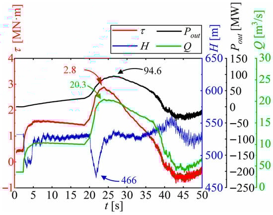
Figure 6.
The correlation between changes in flow rate, torque, and power during a pump-turbine’s start-up process and the opening angles of guide vanes [59].
Runner design theories are optimization methods based on CFD, which repeatedly modify blade shapes by analyzing internal flow fields to eliminate undesirable flow structures in the blade passages. For example, Kim et al. [60] enhanced the bidirectional operational efficiency of runners by adjusting the airfoil profiles of low-head pump-turbine runners through the Design of Experiments (DOE) approach. Qin et al. [61] optimized the geometric configuration of the blades’ high-pressure side through a multi-objective optimization strategy, with the design point efficiencies of both pumping and turbine modes set as optimization targets. This modification resulted in respective improvements of 1.17% and 0.46% in the design point efficiencies of the pumping and turbine modes. For instance, Wang et al. [62] put forward a multi-objective optimization design approach for medium-to-high-head pump-turbine runners, which integrates 3D inverse problem design, CFD numerical simulation, DOE, Response Surface Method (RSM), and Multi-Objective Genetic Algorithm (MOGA). This approach not only efficiently enhanced the bidirectional efficiency of runners but also uncovered the impact of control parameters on design point efficiency. Schleiche et al. [63] used the Response Surface Method to design runners for small-capacity pump-turbines. However, most current runner designs focus on benchmarking against specific power station conditions. In the future, runner design research needs to deeply integrate machine learning with fluid mechanics to achieve automated and efficient design.
Numerous studies have investigated the transient instabilities associated with S-shaped characteristics, spanning experimental measurements, numerical simulations, and theoretical analyses. Fu et al. [64] used a 1D–3D coupled simulation approach to investigate high-amplitude pressure pulsations induced by significant head fluctuations during turbine-mode load rejection. Joint time–frequency analysis revealed that besides rotor–stator interaction and local recirculation vortices, Dean vortices in the spiral casing constituted critical contributors to the pulsation mechanism. Widmer et al. [13] conducted numerical simulations and test bench measurements on a model pump-turbine, observing that flow field instability is triggered by two phenomena: fixed vortex formation and rotating stall. Both are induced by flow separation and vortex generation under low flow rate conditions. When guide vane openings are small, the gap between the runner and guide vanes leads to fully developed vortices forming around the inlet edge and vaneless zone, which block the flow passage. In cases of large guide vane openings, rotating stall cells propagate from the runner and vaneless zone into the guide vane and stay vane passages. Furthermore, researchers have noted that rotating stall is not a sufficient condition for the hump phenomenon to occur [65]. The rotating stall was present across all three measured guide vane openings, but the hump phenomenon was only detected at the 8 mm opening. Thus, the correlation between the hump phenomenon and rotating stall demands further in-depth analysis from multiple perspectives, such as the internal flow within the runner, as shown in Figure 7. Zhang et al. [66] utilized various turbulence models to investigate the flow fields in turbine mode, turbine braking mode, near-zero flow mode, and reverse pumping mode along the S-shaped characteristics under a specific guide vane opening, and observed that vortex structures in the guide vanes and runner result in hydraulic losses.
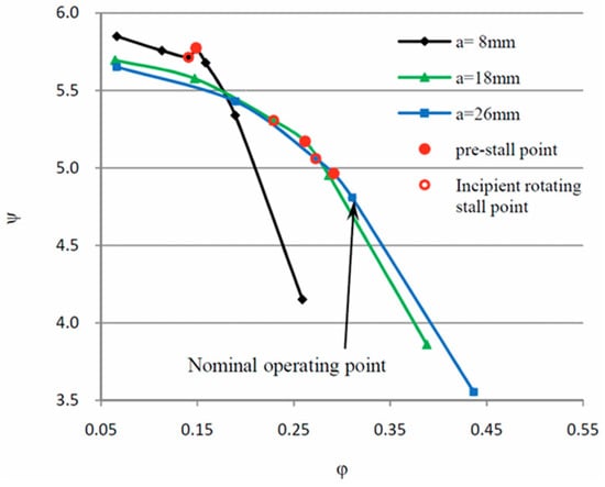
Figure 7.
Pump performance curves and the operating conditions for PIV measurements [65].
Owing to the unstable nature of the complex S-shaped behavior, a great many studies have centered on enhancing the efficiency of pump-turbines within the S-region. Sivakumar et al. [67,68] proposed using variable-speed technology to enhance power station performance, demonstrating that this approach can significantly improve operational efficiency in both turbine and pump modes while expanding the stable operating range of pump-turbines, as shown in Figure 8. Ghoneim [69] achieved smooth flow control in the S-characteristic region by optimizing the matching relationship between photovoltaic panel size/angle and pump rotational speed. Lara et al. [70] utilized an AC–DC–AC direct-drive power converter in a wind-powered pumping system, observing that when the converter efficiency lies between 70% and 95%, its power factor optimization strategy can effectively dampen torque fluctuations in the S-region.
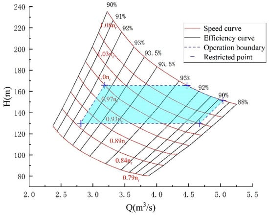
Figure 8.
Regulatory features in power generation mode [68].
In the hump zone, the flow–efficiency curve exhibits a peak, with drastic efficiency changes near the peak. Simulating the flow in this region helps understand the causes of efficiency decline, prompting scientists to analyze the origins of hump-induced operational instability. In recent years, researchers have identified an intriguing phenomenon: when measuring hump characteristics in both decreasing and increasing flow directions, a hysteresis loop forms, thereby enlarging the unstable region. Kaupert and Staubli [71] found in high-specific-speed radial pumps that this hysteresis loop is caused by recirculation at the runner inlet and backflow at the outlet. Experiments and numerical simulations confirm that the hysteretic behavior in the hump zone is linked to rotating stall in the vaneless zone [44]. Li et al. [72] uncovered that hump instability arises from the combined action of Euler momentum and hydraulic losses, and varying magnitudes of these factors can also trigger hysteresis. This phenomenon stems from backflow at the runner inlet and separation vortices near the hub and rim within the guide vanes, and it is associated with the flow direction, as illustrated in Figure 9.
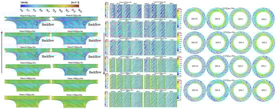
Figure 9.
The main factors contributing to the hysteresis effect in pump-turbines [72].
The cavitation properties of pump-turbines in pumping mode are key factors influencing their safe and stable operation. Cavitation not only results in decreased hydraulic efficiency and component abrasion but may also induce vibrations, noise, and even structural impairment. In the past, cavitation and erosion problems in pump-turbines at an early stage were typically only identified during maintenance. Tao et al. [73] investigated the cavitation initiation mechanism using a NACA0006 hydrofoil. Drawing on insights into the cavitation mechanism, they optimized the blade thickness of pump-turbines through orthogonal tests, which notably lowered the initial cavitation number. With the continuous improvement of the homogeneous equilibrium flow cavitation model by Singhal [74], numerical simulation of cavitation flow inside pump-turbines has become increasingly mature. Using cavitation numerical simulation and testing techniques, Zhu et al. [75] incorporated cavitation performance into a multi-objective optimization process to design a high-head pump-turbine runner, which was experimentally verified to have both high efficiency and cavitation resistance. Liu et al. [76] were the first to adopt multi-objective optimization strategies in developing runners for ultra-high-head pump-turbines, attaining both high efficiency and cavitation resistance. Liu et al. [40] incorporated a cavitation model to examine the hump characteristics of a model pump-turbine, noting that hump behavior might be associated with internal cavitation flow, where cavitation diminishes the pump-turbine’s head. Anciger et al. [77] forecasted rotating stall and incipient cavitation in pump-turbines, while analyzing their underlying causes and effects on operational stability. Li et al. [78,79] investigated the cavitation properties of pump-turbines under partial load and pumping conditions; they analyzed the turbulent kinetic energy distribution on the middle flow surface and bubble distribution on blades across different cavitation coefficients, and explored the correlation between bubble distribution regions and intra-blade passage vortices in the runner.
During the dynamic operation of pump-turbine units, significant changes in internal flow characteristics and external performance metrics often coincide with distinct shifts in energy dissipation mechanisms. The entropy generation approach based on CFD enables the analysis of water flow energy conversion processes across various components, including energy transformation in the spiral casing and energy dissipation within the runner. Additionally, studying the main sources of energy loss under different operating conditions, such as frictional losses and vortex losses, can enhance the research on the unit’s transient characteristics [80,81,82]. Initially, Abu-Hijleh et al. [83] established a laminar entropy production rate (EPR) equation using cylindrical coordinates, laying the foundation for this field. This groundbreaking work was subsequently expanded upon by Kock and Herwig [84], who extended the application of entropy production rate to turbulent flow via Cartesian coordinates. As entropy generation theory continues to advance, a growing number of scholars have employed this approach to analyze energy losses in the unit’s flow field [85,86,87,88,89,90,91,92,93,94,95,96,97]. Pang et al. [88] conducted an in-depth study on the impact of vortex ropes on energy dissipation in the draft tube, finding that severe cavitation significantly enhances internal energy loss within the draft tube. Zhao et al. [89] developed a novel stay vane integrated with bionic protrusions using an entropy generation-based design approach. Computational simulations demonstrated that this configuration effectively mitigated flow separation in guide vanes and runners, leading to a 4% reduction in energy loss. Li et al. [90] put forward an advanced circumferential spoke structure for pump runners, which notably enhanced the stall resistance of mixed-flow pumps. Their simulation results showed that this structure can effectively inhibit leakage flow, thus considerably decreasing the total entropy production (TEP).
3. Pump-Turbine Structural Field Investigation
3.1. Analytical Theoretical Methods
In fluid–structure interaction (FSI) problems, it is necessary to solve the structural dynamics equations, Navier–Stokes (N–S) equations, continuity equations, and finite element discrete equations for FSI problems.
Considering the effect of the fluid, the structural dynamics equation of the discretized elastic body in the fluid is:
In the equations, m, c, k are the mass, damping, and stiffness matrices of the structural system, respectively; F(t) is the excitation vector; δ(t) is the displacement vector.
Assuming the fluid is a compressible and inviscid fluid, with uniform average density and pressure throughout the fluid domain, the N–S equations and continuity equation can be simplified into the acoustic wave equation.
In the equation, c is the propagation speed of sound waves in the fluid, . k is the bulk modulus of the fluid; is the average density of the fluid; P is the acoustic pressure; t is time.
There is the following relationship between the normal pressure gradient of the fluid and the normal acceleration of the solid:
, n is the unit normal vector of the coupling surface, is the displacement vector of the structure on the coupling surface.
Considering the influence of the coupling surface, the acoustic wave equation can be discretized as:
is the fluid mass matrix, is the fluid damping matrix, is the fluid stiffness matrix, is the coupling mass matrix.
To fully describe the fluid–structure interaction (FSI) problem, adding the fluid pressure on the coupling surface to the structural dynamic equation yields the coupled structural dynamic equation:
Combining Equations (4) and (5), the finite element discrete equations that fully describe the fluid–structure interaction problem can be expressed as:
, .
3.2. Natural Modal Characteristics of Pump-Turbines and Added Water Mass
Ascertaining the natural frequencies and mode shapes of pump-turbine structures to comprehend their vibration properties lays a foundation for preventing resonance. Initial investigations were conducted on simple rotating discs submerged in water to establish a baseline understanding before progressing to more complex geometries of pump-turbine runners. The Swiss Federal Institute of Technology in Zurich first discovered the frequency splitting phenomenon of rotating discs in water [91]. Presas et al. [92,93,94] and Roig et al. [95] performed a sequence of experimental investigations on the natural modes of rotating discs in water tanks. These tests were conducted under static conditions, with the runner immersed in a water-filled tank. The runner was excited at specific frequencies using impact hammers or piezoelectric patches, and responses were measured with accelerometers, as shown in Figure 10. The experimental data obtained can be used to verify theoretical predictions and numerical calculation results.
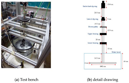
Figure 10.
Test bench for rotating discs in water [95].
Numerical simulations use computational domains similar to experimental configurations to facilitate comparison with experimental results. He et al. [96] proposed a resonance curve prediction method to forecast runner resonance by evaluating the influence of clearances on the added mass and dynamic stress of pump-turbine runners. The meshes for simulation are shown in Figure 11. It was observed that clearance fluid exerts a notable influence on resonance conditions, whereas for non-resonant operating points, the impact of clearances on dynamic stress amplitude is relatively slight. The modal properties of pump-turbines in water differ from those in air, as depicted in Figure 12.
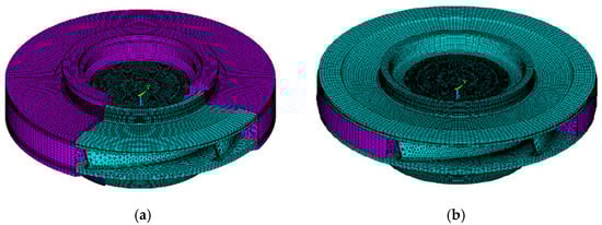
Figure 11.
(a) Runner structure and real flow passage water domain. (b) Runner structure and inner fluid water domain without gaps [96].
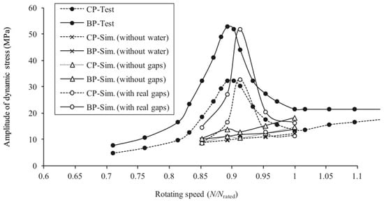
Figure 12.
The comparison of dynamic stress results between calculation and test of natural frequencies in the air and water of a model pump-turbine runner [97].
The Swiss Federal Institute of Technology in Lausanne first identified the natural frequency shift phenomenon of cavitating hydrofoils on a cavitation test bench [97]. Zeng et al. [98,99] investigated the vortex shedding formation process, added mass, and hydrodynamic damping ratio of NACA 0009 hydrofoils at varying flow velocities, noting that the added mass of water affects the unit’s natural frequency, rendering it lower than that in air. Therefore, research into the wet modal characteristics of rotor systems provides a theoretical basis for preventing severe failures caused by resonance [22]. Currently, most researchers focus on the modal characteristics of runners under the influence of added mass. In addition to considering the effect of added mass in water, the impact of connecting shafts on the modal characteristics of rotating components must also be taken into account [100]. Factors such as bearing supports and magnetic fields influence the critical speed of rotor systems [101]. Eusquiza et al. [102] conducted experimental studies on the influence of rotor systems on runner modal characteristics by comparing the modal characteristics of runners in a suspended state and when installed on shafts. They observed that considering the shaft increases the runner’s natural frequency.
4. Hydrodynamic Vibration of Pump-Turbines
In pumped storage power stations, transient processes may give rise to high-pressure pulsation situations, leading to severe structural vibrations in pump-turbines, potential damage to structural components, shortened service life of bearing systems, and excessive power consumption. Especially during transients, the peak of pressure pulsations may cause instantaneous overloading of turbine components, increasing the dynamic load on guide vanes to 5–6 times that under rated conditions. Therefore, studying the flow-induced vibration of structural components in large pump-turbine units during transient processes is of critical importance. Common causes of unit vibration include: rotor–stator interaction, draft tube vortex ropes, and cavitation [103].
4.1. RSI
During the operation of pumped storage units, pressure pulsations arising from the interaction between runner blades and guide vanes constitute one of the primary causes of unit vibration and noise. Hydraulic instability induced by RSI [104], such as substantial fluctuations in pressure and flow rate, stems from the modulation between the potential flow disturbance generated by runner rotation and the flow field disturbance caused by guide vane wakes. This phenomenon subjects the structure to periodic mechanical stress [105] and thermal stress [106]. The frequent changes in these stresses may induce fatigue damage [104,105,107], threatening the safe operation of the equipment.
The frequency and amplitude of RSI can be analyzed via CFD techniques [35,108]. During the operation of pump-turbine units, the wake effect of guide vanes creates a highly non-uniform flow field at the outlet. Under water pressure, as the runner rotates, regular potential flow disturbances also occur at the runner inlet. Periodic rotor–stator interaction phenomena thus occur in the vaneless region between the runner and guide vanes [109]. The periodic flows in stationary and rotating systems can be represented by the following Fourier series:
In the equation, and represent the pressure pulsations of the stationary system and rotating system, m and n are the harmonic orders, and n denote the amplitude and phase of the n harmonic of the stationary system, while and m represent the amplitude and phase of the m harmonic of the rotating system. and are the angular coordinates of the stationary system and rotating system, respectively. is the number of guide vanes, and is the number of runner blades.
The final pressure field resulting from the interaction between moving runner blades and guide vanes can be described by a strong modulation process. This modulation process can be regarded as the product of the two perturbations in Equations (7) and (8). From a stationary reference frame, the angular coordinate of the runner can be expressed as , and the modulated pressure pulsation can be written as:
In the equation, is the amplitude of the modulated pressure pulsation. Equation (3) is used to determine the functional relationship between the pressure field and spatial–temporal variations during rotor–stator interaction. The diametral mode (k) caused by rotor–stator interaction is estimated by Equation (4):
During the operation of pump-turbines, flow components such as the runner, guide vanes, head cover, and bottom ring all undergo forced vibration in the hydraulic excitation mode generated by rotor–stator interaction. The frequencies of the stationary domain and rotating domain are calculated by Formulas (5) and (6).
where is the number of runner blades, and is the number of guide vanes.
In addition, during the start-up, shutdown, load changes, and operational condition transitions of pump-turbines, drastic changes in water flow velocity and pressure distribution occur, generating complex pressure pulsations [110]. These pulsations exert dynamic pressure loads on components such as the runner, guide vanes, and spiral casing, potentially leading to connector failure, reduced equipment reliability, and safety issues. When these dynamic forces coincide with the natural frequency of the components, resonance takes place. Under resonant circumstances, the forces undergo amplification [111], which further exacerbates vibrations and leads to fatigue cracks or structural component damage [22], as illustrated in Figure 13.
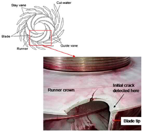
Figure 13.
Diagram of the runner and distributor, along with an image of the fractured runner [22].
To clarify the mechanism of rotor–stator interaction between pump-turbine runner blades and guide vanes, Nicolet et al. [112] constructed a simplified hydroacoustic model of excitation sources driven by valve grids between stationary and rotating components, based on the flow field distribution in the vaneless zone, and derived the impact of resonance conditions on pressure pulsations. Egusquiza et al. [22] investigated the flow-induced vibration caused by rotor–stator interaction in a pump-turbine with 7 blades and 16 guide vanes. They observed that the maximum deformation of the runner occurred at the outer diameter where the blades connect to the crown—a key area exposed to pressure pulsations during operation, as shown in Figure 14. As depicted in Figure 15, the runner’s second-order natural frequency (186 Hz) was close to the excitation frequency (also a second-order mode shape), which resulted in severe runner vibration and eventually fatigue failure.
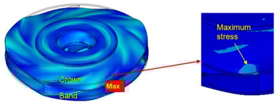
Figure 14.
Distribution of equivalent stress on the runner [22].
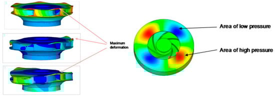
Figure 15.
Mode shapes of the runner [22].
4.2. Draft Tube Vortex Rope
When operating under off-design conditions, pump-turbines display various time-varying phenomena [113], as illustrated in Figure 16. These phenomena mainly occur in the conical segment of the draft tube, depending on the swirl intensity and flow velocity, three distinct types of vortex ropes may develop within the draft tube: spiral, double-helical, and columnar [114]. Single-spiral vortex ropes induce pressure pulsations at lower frequencies 0.2–0.4fn, while double-helical vortex ropes generate higher-frequency pulsations 0.75–1.19fn. Draft tube vortex ropes can cause pressure pulsations, severe vibrations, fatigue loading, and premature failure of equipment components. Thus, hydraulic instability problems like pressure pulsations in the unit triggered by vortex ropes are particularly notable, especially when the pulsation frequency gets close to the structural natural frequency [115].
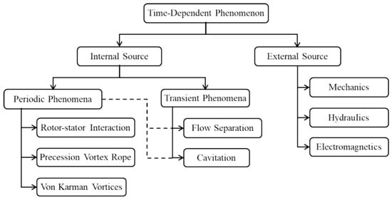
Figure 16.
Various time-dependent phenomena at different operating conditions of a pump-turbine [113].
Under off-design operating conditions, vortex ropes and associated flow instabilities in the draft tube give rise to inadequate pressure recovery, thereby lowering the efficiency of reversible pump-turbines [116]. He et al. [117] performed numerical analyses of vortex ropes under 60%, 86.7%, and 100% load conditions, observing spiral vortex ropes at 86.7% partial load. As depicted in Figure 17, the flow in the draft tube was highly turbulent under 60% partial load, with heightened intensities of other vortices such as runner blade passage vortices. At low and high loads, the swirl intensity of vortex ropes was moderate, resulting in smaller pressure pulsation amplitudes in the draft tube; at medium loads, the swirl intensity was greater, leading to larger pulsation amplitudes; at 100% load, the swirl intensity was extremely low, and the pressure pulsation amplitude in the draft tube was minimal.
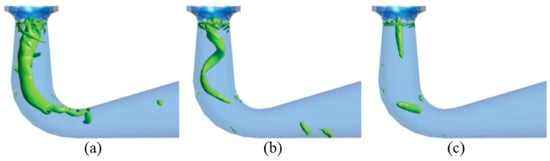
Figure 17.
Draft tube vortex rope at (a) 60%, (b) 86.7%, and (c) 100% load conditions [117].
Under the conditions of a small guide vane opening (GVO), power oscillations in pumped hydrostorage plants (PHSPs) are directly associated with draft tube surging. The amplitude of these oscillations is dependent on the ratio between the draft tube surging frequency and the runner rotation frequency, which is typically around one-third of the runner rotation frequency. Kim et al. [118] investigated the characteristics of vortex ropes in the draft tube of a reversible pump-turbine (RPT) under different guide vane angles, and observed low-frequency pressure pulsations of 0.2fn under low-flow conditions, as illustrated in Figure 18. When the guide vane angle (GVA) was 7°, in addition to the vortex rope frequency of 0.2fn, a frequency of 3.2fn and the blade passing frequency (BPF) were also detected. The former originated from inter-blade vortices, while the latter was caused by RSI between guide vanes and the runner. Under low-flow conditions with a small GVO, the flow pattern in the passage is more sensitive to changes in the blade trailing edge, as adverse flow characteristics such as eddies and flow separation are more pronounced. As a result, researchers have observed that increasing the maximum thickness of guide vanes and the roundness of their heads can mitigate the swirl in the draft tube elbow and diffuser section, thereby reducing pressure pulsations by 6–9% [119].
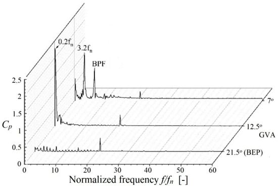
Figure 18.
Normalized unsteady pressure in the draft tube at different guide vane angles [119].
4.3. Cavitation
Pumped hydrostorage power plants are developing towards higher water heads and larger capacities, among which cavitation problems are one of the key factors restricting the advancement of pump-turbines. Cavitation can result in decreased efficiency and head of pump-turbines. Cavitation bubbles may block the flow passages of pump-turbines, and the processes of bubble generation, growth, diffusion, and collapse can induce a series of adverse effects such as noise and vibration [120]. The positions where cavitation occurs in pump mode and turbine mode differ significantly. In turbine operation, cavitation bubbles typically start near the outlet edge of the impeller blades [121,122], and develop into draft tube vortex ropes [123]. For pumps sharing the same working principle as the pump mode of pump-turbines, cavitation usually takes place near the inlet edge of the blades [124].
Researchers have observed that for a pump-turbine unit under specific installation conditions, flow rate, and water head, the cavitation formation conditions in pump mode are more severe than those in turbine mode [125]. Premkumar et al. [126] investigated the cavitation characteristics of reversible impellers with S-shaped blades and indicated that the impact of cavitation in pump mode is more significant than in turbine mode. Yuan et al. [127] found that cavitation occurs in pump-turbines during pumping operation under high-rotational-speed or high-flow-rate conditions, and it worsens as the rotational speed and flow rate increase. Under low-flow-rate conditions, vibration energy rises rapidly with the occurrence of rotating stall. In addition, important progress has been made in design optimization based on flow field analysis. By combining numerical simulation and experiments, researchers can more effectively optimize the hydraulic performance of the units, reduce flow losses, enhance efficiency, and lower cavitation risks. For instance, Fu et al. [128] revealed the cavitation effects in the transient behavior of a prototype pump-turbine during load rejection through numerical simulation, identified the main mechanisms causing pressure pulsations and speed changes, and verified the influence of bubble collapse and vortex rope interaction on complex pressure frequency components.
5. Fatigue Failure of Pump-Turbines
Under steady-state operating conditions, the frequency of forced excitation in pump-turbines remains unchanged. However, during transient processes such as startup, shutdown, or full load rejection, the excitation frequency changes with the runner speed and may even surpass the runner’s natural frequency (first-order mode shape). For transient processes, Chen et al. utilized one-way fluid–structure interaction (FSI) numerical simulations to study the dynamic stress of the runner during pump-turbine startup and load rejection and derived the variation law of runner dynamic stress in transient processes. Relevant studies have indicated that runner damage during transient processes is more severe than that under steady-state conditions. Tang et al. [129] performed CFD-FEM numerical simulations on pump-turbines under load rejection conditions. The results demonstrate that rotational speed is the most critical factor affecting the pressure pulsation and dynamic stress of the runner. The pressure pulsation in the runner is most intense under the maximum rotational speed condition, and both the dynamic stress value and amplitude of the blades are higher than those under other conditions. Pressure pulsation causes fluctuations in the runner’s dynamic stress, and the two share consistent spectral characteristics. Since the frequency of the hydraulic excitation force differs significantly from the runner’s natural frequency, the probability of runner resonance under the calculated conditions is low.
In addition to the runner, bolts also bear significant hydraulic excitation forces from the head cover, which may result in excessive bolt stress, insufficient preload, and alternating dynamic loads—thereby causing bolt fatigue, cracking, or even fracture. A similar incident occurred at a Chinese pumped storage power plant in 2016, where the head cover bolts of a pump-turbine unit experienced brittle fracture. As shown in Figure 19, high-pressure water lifted the head cover and rotor, and eventually flooded the power plant workshop [130]. To reduce leakage, sufficient preload must be applied to the bolts to ensure a tight fit between the head cover and the stay ring. Liu [131] investigated the causes of high-strength bolt fractures at the root of wind turbine blades and found that the fractures were due to accelerated fatigue caused by stress concentration in low-temperature environments. Casanova et al. [132] found that different preload values lead to varying degrees of bolt damage. Grimsmo et al. [133] discovered that the thread failure mode is related to the nut’s position: placing the nut near the end of the bolt thread leads to thread failure, while bolt fracture occurs when the nut is sufficiently far from the thread end. In conclusion, numerous factors can cause bolt failure, including stress concentration, accelerated fatigue due to high alternating loads, and insufficient preload.
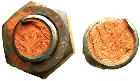
Figure 19.
Fracture of two head-cover bolts [130].
During the operation of pump-turbines, pressure fluctuations, flow velocity changes, and cavitation phenomena in the water flow can all cause fatigue damage to their components. Seydoux [134] studied different startup transient sequences of turbines tested on scaled models to evaluate the equivalent damage effects on the runner, with results highlighting the advantages of using variable-speed technology during unit startup. Vibration sensors installed on turbine bearings, frames, and other components can be used to real-time monitor the unit’s vibration, promptly detect signs of fatigue damage, and assess its severity [135]. It is also possible to directly measure the magnitude and distribution of stresses experienced by turbine components during operation. By analyzing stress data, the stress state of components can be understood to determine whether there are risks of stress concentration and fatigue damage. Commonly used stress monitoring methods include the resistance strain gauge method [136] and the fiber Bragg grating method [137].
High dynamic stress values are among the primary causes of fatigue cracks in runner blades. Martellotti [138] observed that in the low-load region, significant draft tube pressure pulsations are the main factor contributing to fluctuations in the dynamic stress values of runner blades. In the high-load region, the primary cause of maximum dynamic stress in the runner stems from large pressure pulsations behind the unit’s stay vanes and guide vanes. During the load rejection process of pump-turbines, pressure pulsations induced by water hammer effects can result in high stresses, causing damage to turbine runners, head covers, stay rings, bottom rings, head cover bolts, and bottom ring bolts. Huang et al. [29] validated CFD calculation results by measuring pressure changes during the load rejection process of a high-head pumped storage power plant. They mapped the obtained pressure distribution in the flow passage to the finite element model of the pump-turbine unit’s fixed components and found that the maximum stress in head cover bolts and bottom ring bolts occurs at the bolt fillet adjacent to the stay ring, with the bolt stress varying over time during load rejection. Khalfaoui [139] employed large CFD grids and turbulence models capable of resolving scales to numerically predict dynamic behavior under deep part-load (DPL) conditions, accurately replicating the measured dynamic pressure and strain oscillations in terms of amplitude and trend. A new, atypical critical location that dominates fatigue damage under deep part-load conditions was also identified, and a method for determining critical locations of fatigue damage accumulation was proposed. In conclusion, investigating the stress distribution and variation patterns of pump-turbines under dynamic loads can serve to evaluate the fatigue performance and structural reliability.
6. Conclusions
Due to their bidirectional operation characteristics and frequent working condition switching, pump-turbines exhibit prominent features of strong multi-physical field coupling and complex dynamic responses in fluid–structure interaction (FSI) problems, posing core challenges to the stability, reliability, and service life of the units. This paper reviews the fluid–structure coupling issues in the flow field and structural field of pump-turbines, providing a comprehensive and rigorous overview in different chapters. Based on fluid field analysis and FSI analysis comprising additional mass, damping, vibration, stress concentration, and fatigue load, the existing research problems and directions are emphatically discussed.
- (1)
- Current research, starting from flow field analysis, mainly focuses on problems such as efficiency, stability, and cavitation in the “S” characteristic zone and hump zone. Studies have revealed that in the water flow through components like runners and guide vanes, backflow, vortex, and other phenomena may occur, which affect energy conversion efficiency. Pump-turbines are prone to exhibit unstable phenomena, easily triggering hydraulic and mechanical vibrations. Variable-speed technology has been proven to enhance unit performance, and variable speed regulation is recognized as a future development trend for pump-turbines.
- (2)
- Research on the natural modal characteristics of pump-turbines and the additional mass of water shows that the additional mass effect of fluid has a significant influence on structural vibration, which can reduce the natural frequency of the runner in water by up to 60%. The natural frequency of pump-turbine structures is obviously affected by the additional mass of fluid and is closely related to the vibration mode. Factors such as clearance fluid, connecting shafts, bearing supports and magnetic fields will all change the modal characteristics of the rotor system.
- (3)
- The influence of hydraulic excitation force on the unit structure is as follows. During steady-state operation, the forced excitation frequency is determined by the number of blades, guide vanes, and rotational speed. In transient conditions such as start-stop and load rejection, the excitation frequency changes with the rotational speed and may approach the natural frequency of the runner, triggering resonance. Pressure pulsations generated by rotor–stator interaction (RSI) are the main vibration source, whose frequency can be characterized by Fourier series and diametral mode formulas, leading to stress concentration in areas such as blade T-joints and head cover bolts. During load rejection, rotational speed is the core factor affecting pressure pulsations and dynamic stress—the vibration is most intense at the maximum speed, and the frequency spectra of pressure pulsations and dynamic stress are consistent.
- (4)
- Dynamic stress is the dominant factor in fatigue damage. The T-joints at the leading/trailing edges of blades, head cover bolts, and the outer edge of the runner–crown connection are high-incidence areas for fatigue cracks. The vortex ropes in the draft tube under low-load conditions and the pressure pulsations of guide vanes under high-load conditions are the main causes of fatigue damage in pump-turbines. Research on fluid–structure coupling in pump-turbines needs to break through the dual bottlenecks of basic theory and engineering applications. Through the deep integration of precise modeling, experimental verification, and intelligent design, core issues such as vibration suppression and fatigue life prediction can be addressed, providing theoretical and technical support for the safe and reliable operation of high-parameter, wide-working-condition pumped storage units.
Author Contributions
Data curation, writing—original draft, L.S.; investigation, formal analysis, methodology, J.Z.; project administration, software, X.H.; validation, conceptualization, S.G.; funding acquisition, Z.W.; writing—review and editing, J.L. All authors have read and agreed to the published version of the manuscript.
Funding
This research was funded by Henan Jiufengshan Pumped Storage Energy Co., Ltd. (JFSX-CG-Y-2025-0002).
Data Availability Statement
Not applicable.
Acknowledgments
We are sincerely grateful to the project Calculation and analysis of flow-induced dynamic characteristics of prototype unit of the pumped storage power station.
Conflicts of Interest
Authors Jianfeng Zhu and Shenjie Gao were employed by the company Henan Jiufengshan Pumped Storage Co., Ltd. Author Xingxing Huang was employed by the company S.C.I. Energy (Swiss). The remaining authors declare that the research was conducted in the absence of any commercial or financial relationships that could be construed as a potential conflict of interest.
References
- Ostergaard, P.A.; Duic, N.; Noorollahi, Y.; Kalogirou, S. Renewable energy for sustainable development. Renew. Energy 2022, 199, 1145–1152. [Google Scholar] [CrossRef]
- Gayen, D.; Chatterjee, R.; Roy, S. A review on environmental impacts of renewable energy for sustainable development. Int. J. Environ. Sci. Technol. 2024, 21, 5285–5310. [Google Scholar] [CrossRef]
- Zhou, X.; Chen, S.; Lu, Z. Review and Prospect for Power System Development and Related Technologies: A Concept of Three-generation Power Systems. Proc. Chin. Soc. Electr. Eng. 2013, 33, 1–11. [Google Scholar]
- Denholm, P.; Ela, E.; Kirby, B.; Milligan, M. Role of Energy Storage with Renewable Electricity Generation (Report Summary) (Presentation); National Renewable Energy Lab. (NREL): Golden, CO, USA, 2010. [Google Scholar]
- World Energy Council. E-Storage: Shifting from Cost to Value—Wind and Solar Applications; World Energy Council: London, UK, 2016. [Google Scholar]
- Iliev, I.; Trivedi, C.; Dahlhaug, O.G. Variable-speed operation of Francis turbines: A review of the perspectives and challenges. Renew. Sustain. Energy Rev. 2019, 103, 109–121. [Google Scholar] [CrossRef]
- Zuo, Z.G.; Liu, S.H.; Sun, Y.K.; Wu, Y.L. Pressure fluctuations in the vaneless space of High-head pump-turbines—A review. Renew. Sustain. Energy Rev. 2015, 41, 965–974. [Google Scholar] [CrossRef]
- Birajdar, R.; Keste, A. Prediction of Flow-Induced Vibrations due to Impeller Hydraulic Unbalance in Vertical Turbine Pumps Using One-Way Fluid-Structure Interaction. J. Vib. Eng. Technol. 2020, 8, 417–430. [Google Scholar] [CrossRef]
- He, L.Y.; Wang, Z.W.; Kurosawa, S.; Nakahara, Y. Resonance investigation of pump-turbine during startup process. In Proceedings of the 27th IAHR Symposium on Hydraulic Machinery and Systems (IAHR 2014), Montreal, QC, Canada, 22–26 September 2014; Volume 22. [Google Scholar] [CrossRef]
- Huth, H. Fatigue Design of Hydraulic Turbine Runners. Ph.D. Thesis, Norwegian University of Science and Technology, Trondheim, Norway, 2005. [Google Scholar]
- Chen, F.N.; Yang, X.L.; Bi, H.L.; Mao, Z.Y.; Luo, Y.Y.; Liujingshi; Fan, H.G.; Wang, Z.W. Analysis of Dynamic Stresses of Pump-Turbine Runner during Load Rejection Process in Turbine Mode. In Proceedings of the 30th IAHR Symposium on Hydraulic Machinery and Systems (IAHR 2020), Lausanne, Switzerland, 21–26 March 2021; Volume 774. [Google Scholar] [CrossRef]
- Thibault, D.; Gagnon, M.; Godin, S. Bridging the gap between metallurgy and fatigue reliability of hydraulic turbine runners. IOP Conf. Ser. Earth Environ. Sci. 2014, 22, 012019. [Google Scholar] [CrossRef]
- Widmer, C.; Staubli, T.; Ledergerber, N. Unstable Characteristics and Rotating Stall in Turbine Brake Operation of Pump-Turbines. J. Fluids Eng. 2011, 133, 041101. [Google Scholar] [CrossRef]
- Hasmatuchi, V. Hydrodynamics of a Pump-Turbine Operating at Off-Design Conditions in Generating Mode. Ph.D. Thesis, École Polytechnique Fédérale de Lausanne, Écublens, Switzerland, 2012. [Google Scholar]
- Zhao, X.R.; Xiao, Y.X.; Wang, Z.W.; Luo, H.Y.; Ahn, S.H.; Yao, Y.Y.; Fan, H.G. Numerical analysis of non-axisymmetric flow characteristic for a pump-turbine impeller at pump off-design condition. Renew. Energy 2018, 115, 1075–1085. [Google Scholar] [CrossRef]
- Giosio, D.R.; Henderson, A.D.; Walker, J.M.; Brandner, P.A.; Sargison, J.E.; Gautam, P. Design and performance evaluation of a pump-as-turbine micro-hydro test facility with incorporated inlet flow control. Renew. Energy 2015, 78, 1–6. [Google Scholar] [CrossRef]
- Zhang, X.X.; Cheng, Y.G.; Xia, L.S.; Yang, J.D.; Qian, Z.D. Looping Dynamic Characteristics of a Pump-Turbine in the S-shaped Region During Runaway. J. Fluids Eng.-Trans. ASME 2016, 138, 091102. [Google Scholar] [CrossRef]
- Xia, L.; Cheng, Y.; Yang, Z.; You, J.; Yang, J.; Qian, Z. Evolutions of Pressure Fluctuations and Runner Loads During Runaway Processes of a Pump-Turbine. J. Fluids Eng. 2017, 139, 091101. [Google Scholar] [CrossRef]
- Yang, Z.Y.; Cheng, Y.G.; Xia, L.S.; Meng, W.W.; Liu, K.; Zhang, X.X. Evolutions of flow patterns and pressure fluctuations in a prototype pump-turbine during the runaway transient process after pump-trip. Renew. Energy 2020, 152, 1149–1159. [Google Scholar] [CrossRef]
- Yin, X.L.; Huang, X.X.; Zhang, S.Z.; Bi, H.L.; Wang, Z.W. Numerical Investigation of Flow and Structural Characteristics of a Large High-Head Prototype Pump-Turbine during Turbine Start-Up. Energies 2023, 16, 3743. [Google Scholar] [CrossRef]
- Guo, J.X.; Zhou, D.Q.; Chen, H.X.; Wang, H.B. Flow-induced vibration analysis in a pump-turbine runner under transient operating conditions. Eng. Appl. Comput. Fluid Mech. 2023, 17, 2266662. [Google Scholar] [CrossRef]
- Egusquiza, E.; Valero, C.; Huang, X.X.; Jou, E.; Guardo, A.; Rodriguez, C. Failure investigation of a large pump-turbine runner. Eng. Fail. Anal. 2012, 23, 27–34. [Google Scholar] [CrossRef]
- Menéndez, J.; Fernández-Oro, J.M.; Galdo, M.; Loredo, J. Efficiency analysis of underground pumped storage hydropower plants. J. Energy Storage 2020, 28, 101234. [Google Scholar] [CrossRef]
- Tao, R.; Wang, Z.W. Comparative numerical studies for the flow energy dissipation features in a pump-turbine in pump mode and turbine mode. J. Energy Storage 2021, 41, 102835. [Google Scholar] [CrossRef]
- Jin, F.Y.; Wang, H.M.; Luo, Y.Y.; Presas, A.; Bi, H.L.; Wang, Z.W.; Lin, K.; Lei, X.C.; Yang, X.L. Visualization research of energy dissipation in a pump turbine unit during turbine mode’s starting up. Renew. Energy 2023, 217, 119172. [Google Scholar] [CrossRef]
- Zuo, Z.; Fan, H.; Liu, S.; Wu, Y. S-shaped characteristics on the performance curves of pump-turbines in turbine mode—A review. Renew. Sustain. Energy Rev. 2016, 60, 836–851. [Google Scholar] [CrossRef]
- Staubli, T.; Senn, F.; Sallaberger, M. Instability of Pump-Turbines during Start-up in Turbine Mode. Hydro 2008, 2008, 6–8. [Google Scholar]
- Tanaka, H.; Tsunoda, S. The development of high head single stage pump turbines. In Proceedings of the 10th IAHR Symposium on Hydraulic Machinery, Equipment and Cavitation, Tokyo, Japan, 28 September–2 October 1980. [Google Scholar]
- Huang, X.X.; Chen, L.; Wang, Z.W.; Li, H.B.; Chen, S.Y.; Hu, K.; Li, C.J.; Qiu, L. Stress Characteristic Analysis of Pump-Turbine Head Cover Bolts during Load Rejection Based on Measurement and Simulation. Energies 2022, 15, 9496. [Google Scholar] [CrossRef]
- Pacot, O.; Kato, C.; Guo, Y.; Yamade, Y.; Avellan, F. Large Eddy Simulation of the Rotating Stall in a Pump-Turbine Operated in Pumping Mode at a Part-Load Condition. J. Fluids Eng.-Trans. ASME 2016, 138, 111102. [Google Scholar] [CrossRef]
- Hasmatuchi, V.; Farhat, M.; Roth, S.; Botero, F.; Avellan, F. Experimental Evidence of Rotating Stall in a Pump-Turbine at Off-Design Conditions in Generating Mode. J. Fluids Eng.-Trans. ASME 2011, 133, 051104. [Google Scholar] [CrossRef]
- Li, D.Y.; Sun, Y.K.; Zuo, Z.G.; Liu, S.H.; Wang, H.J.; Li, Z.G. Analysis of Pressure Fluctuations in a Prototype Pump-Turbine with Different Numbers of Runner Blades in Turbine Mode. Energies 2018, 11, 1474. [Google Scholar] [CrossRef]
- Sinha, M.; Pinarbasi, A.; Katz, J. The flow structure during onset and developed states of rotating stall within a vaned diffuser of a centrifugal pump. J. Fluids Eng.-Trans. ASME 2001, 123, 490–499. [Google Scholar] [CrossRef]
- Sano, T.; Nakamura, Y.; Yoshida, Y.; Tsujimoto, Y. Alternate blade stall and rotating stall in a vaned diffuser. JSME Int. J. Ser. B-Fluids Therm. Eng. 2002, 45, 810–819. [Google Scholar] [CrossRef]
- Ciocan, G.D.; Desvignes, V.; Combes, J.F.; Parkinson, E.; Kueny, J.L. Experimental and numerical unsteady analysis of rotor-stator interaction in a pump-turbine. In Proceedings of the XIX IAHR Symposium on Hydraulic Machinery and Cavitation, Singapore, 9–11 September 1998; Volumes 1 and 2, pp. 210–219. [Google Scholar]
- Braun, O.; Kueny, J.L.; Avellan, F. Numerical analysis of flow phenomena related to the unstable energy-discharge characteristic of a pump-turbine in pump mode. In Proceedings of the ASME Fluids Engineering Division Summer Conference—2005, Houston, TX, USA, 19–23 June 2005; Volume 1, pp. 1075–1080. [Google Scholar]
- Li, D.; Gong, R.; Wang, H.; Xiang, G.; Wei, X.; Qin, D. Entropy production analysis for hump characteristics of a pump turbine model. Chin. J. Mech. Eng. 2016, 29, 803–812. [Google Scholar] [CrossRef]
- Li, D.; Gong, R.; Wang, H.; Han, L.; Wei, X.; Qin, D. Analysis of vorticity dynamics for hump characteristics of a pump turbine model. J. Mech. Sci. Technol. 2016, 30, 3641–3650. [Google Scholar] [CrossRef]
- Cui, W.; Feng, J.; Zhu, G.; Wang, L.; Wu, G.; Luo, X. Characteristics of rigid vorticity and pressure pulsation in the hump region under pump mode of a pump-turbine. J. Energy Storage 2025, 131, 117583. [Google Scholar] [CrossRef]
- Liu, J.; Liu, S.; Wu, Y.; Jiao, L.; Wang, L.; Sun, Y. Numerical investigation of the hump characteristic of a pump–turbine based on an improved cavitation model. Comput. Fluids 2012, 68, 105–111. [Google Scholar] [CrossRef]
- Li, D.; Han, L.; Wang, H.; Gong, R.-Z.; Wei, X.; Qin, D.-Q. Flow characteristics prediction in pump mode of a pump turbine using large eddy simulation. Proc. Inst. Mech. Eng. Part E J. Process. Mech. Eng. 2016, 231, 961–977. [Google Scholar] [CrossRef]
- Erne, S.; Edinger, G.; Bauer, C. Numerical study of the stay vane channel-flow in a reversible pump turbine at off-design conditions. In Proceedings of the 16th International Conference on Fluid Flow Technologies, Budapest, Hungary, 1–4 September 2015. [Google Scholar]
- Ješe, U.; Fortes-Patella, R.; Dular, M. Numerical Study of Pump-Turbine Instabilities Under Pumping Mode Off-Design Conditions. In Proceedings of the ASME/JSME/KSME 2015 Joint Fluids Engineering Conference, Seoul, Republic of Korea, 26–31 July 2015. [Google Scholar]
- Ran, H.; Luo, X.; Zhu, L.; Zhang, Y.; Wang, X.; Xu, H. Experimental study of the pressure fluctuations in a pump turbine at large partial flow conditions. Chin. J. Mech. Eng. 2012, 25, 1205–1209. [Google Scholar] [CrossRef]
- Yang, J.; Pavesi, G.; Yuan, S.; Cavazzini, G.; Ardizzon, G. Experimental Characterization of a Pump-Turbine in Pump Mode at Hump Instability Region. J. Fluids Eng.-Trans. ASME 2015, 137, 051109. [Google Scholar] [CrossRef]
- Deyou, L.; Hongjie, W.; Gaoming, X.; Ruzhi, G.; Xianzhu, W.; Zhansheng, L. Unsteady simulation and analysis for hump characteristics of a pump turbine model. Renew. Energy 2015, 77, 32–42. [Google Scholar] [CrossRef]
- Jaworski, Z.; Dyster, K.N.; Nienow, A.W. The effect of size, location and pumping direction of pitched blade turbine impellers on flow patterns: LDA measurements and CFD predictions. Chem. Eng. Res. Des. 2001, 79, 887–894. [Google Scholar] [CrossRef]
- Krappel, T.; Kuhlmann, H.; Kirschner, O.; Ruprecht, A.; Riedelbauch, S. Validation of an IDDES-type turbulence model and application to a Francis pump turbine flow simulation in comparison with experimental results. Int. J. Heat Fluid Flow 2015, 55, 167–179. [Google Scholar] [CrossRef]
- Khan, F.R.; Rielly, C.D.; Brown, D.A.R. Angle-resolved stereo-PIV measurements close to a down-pumping pitched-blade turbine. Chem. Eng. Sci. 2006, 61, 2799–2806. [Google Scholar] [CrossRef]
- Liu, D.M.; Xu, W.L.; Zhao, Y.Z. Experimental study of the flow field of a high head model pump turbine based on PIV technique. J. Hydrodyn. 2021, 33, 1045–1055. [Google Scholar] [CrossRef]
- Ren, Y.; Bi, Y.; Wu, Q. Study on flow characteristics in the runner of Francis Pump-turbine based on piv technology. Chin. J. Hydrodynomics 2019, 34, 720–725. [Google Scholar]
- Lai, X.-D.; Liang, Q.-W.; Ye, D.-X.; Chen, X.-M.; Xia, M.-M. Experimental investigation of flows inside draft tube of a high-head pump-turbine. Renew. Energy 2019, 133, 731–742. [Google Scholar] [CrossRef]
- Liu, D.M.; Zhao, Y.Z.; Zuo, Z.G. Experimental research on flow field in the draft tube of pump turbines based on LDV. In Proceedings of the 29th IAHR Symposium on Hydraulic Machinery and Systems, Kyoto, Japan, 16–21 September 2018; Volume 240. [Google Scholar] [CrossRef]
- Carravetta, A.; Fecarotta, O.; Martino, R.; Antipodi, L. PAT efficiency variation with design parameters. In Proceedings of the 12th International Conference on Computing and Control for The Water Industry, CCWI2013, Perugia, Italy, 2–4 September 2013; Volume 70, pp. 285–291. [Google Scholar] [CrossRef]
- Plua, F.A.; Sanchez-Romero, F.-J.; Hidalgo, V.; Lopez-Jimenez, P.A.; Perez-Sanchez, M. Variable Speed Control in PATs: Theoretical, Experimental and Numerical Modelling. Water 2023, 15, 1928. [Google Scholar] [CrossRef]
- Fecarotta, O.; Carravetta, A.; Ramos, H.M.; Martino, R. An improved affinity model to enhance variable operating strategy for pumps used as turbines. J. Hydraul. Res. 2016, 54, 332–341. [Google Scholar] [CrossRef]
- Xiao, Y.-X.; Wang, Z.-W.; Zhang, J.; Luo, Y.-Y. Numerical predictions of pressure pulses in a Francis pump turbine with misaligned guide vanes. J. Hydrodyn. Ser. B 2014, 26, 250–256. [Google Scholar] [CrossRef]
- Xiao, Y.X.; Xiao, R.F. Transient simulation of a pump-turbine with misaligned guide vanes during turbine model start-up. ACTA Mech. Sin. 2014, 30, 646–655. [Google Scholar] [CrossRef]
- Jin, F.; Luo, Y.; Wang, Z. Research on the starting-up process of a prototype reversible pump turbine with misaligned guide vanes: An energy loss analysis. Energy 2024, 304, 132219. [Google Scholar] [CrossRef]
- Kim, J.H.; Cho, B.M.; Kim, S.; Kim, J.W.; Suh, J.W.; Choi, Y.S.; Kanemoto, T.; Kim, J.H. Design technique to improve the energy efficiency of a counter-rotating type pump-turbine. Renew. Energy 2017, 101, 647–659. [Google Scholar] [CrossRef]
- Qin, Y.L.; Li, D.Y.; Wang, H.J.; Liu, Z.S.; Wei, X.Z.; Wang, X.H. Multi-objective optimization design on high pressure side of a pump-turbine runner with high efficiency. Renew. Energy 2022, 190, 103–120. [Google Scholar] [CrossRef]
- Wang, X.; Cao, S.; Tan, L. Full 3-D viscous optimization design of a reversible pump turbine runner. IOP Conf. Ser. Mater. Sci. Eng. 2013, 52, 022014. [Google Scholar] [CrossRef]
- Schleicher, W.C.; Oztekin, A. Hydraulic design and optimization of a modular pump-turbine runner. Energy Convers. Manag. 2015, 93, 388–398. [Google Scholar] [CrossRef]
- Fu, X.L.; Li, D.Y.; Song, Y.C.; Wang, H.J.; Wei, X.Z. High-amplitude pressure fluctuations of a pump-turbine with large head variable ratio during the turbine load rejection process. Sci. China-Technol. Sci. 2023, 66, 2575–2585. [Google Scholar] [CrossRef]
- Xue, P.; Liu, Z.P.; Lu, L.; Gao, Z.X.; Meng, X.C. Experimental Research on the Rotating Stall of a Pump Turbine in Pump Mode. Water 2019, 11, 2426. [Google Scholar] [CrossRef]
- Zhang, L.; Wang, Z.; Chang, J. Flow of Pump-turbine on S-shaped Region of Complete Characteristics. Trans. Chin. Soc. Agric. Mach. 2011, 42, 39–43. [Google Scholar]
- Sivakumar, N.; Das, D.; Padhy, N.P. Variable speed operation of reversible pump-turbines at Kadamparai pumped storage plant—A case study. Energy Convers. Manag. 2014, 78, 96–104. [Google Scholar] [CrossRef]
- Wang, H.; Ma, Z.J. Regulation Characteristics and Load Optimization of Pump-Turbine in Variable-Speed Operation. Energies 2021, 14, 8484. [Google Scholar] [CrossRef]
- Ghoneim, A.A. Design optimization of photovoltaic powered water pumping systems. Energy Convers. Manag. 2006, 47, 1449–1463. [Google Scholar] [CrossRef]
- Lara, D.; Merino, G.; Salazar, L. Power converter with maximum power point tracking MPPT for small wind-electric pumping systems. Energy Convers. Manag. 2015, 97, 53–62. [Google Scholar] [CrossRef]
- Kaupert, K.A.; Staubli, T. The Unsteady Pressure Field in a High Specific Speed Centrifugal Pump Impeller—Part II: Transient Hysteresis in the Characteristic. J. Fluids Eng. 1999, 121, 627–632. [Google Scholar] [CrossRef]
- Li, D.; Wang, H.; Qin, Y.; Wei, X.; Qin, D. Numerical simulation of hysteresis characteristic in the hump region of a pump-turbine model. Renew. Energy 2018, 115, 433–447. [Google Scholar] [CrossRef]
- Tao, R.; Xiao, R.F.; Wang, F.J.; Liu, W.C. Improving the cavitation inception performance of a reversible pump turbine in pump mode by blade profile redesign: Design concept, method and applications. Renew. Energy 2019, 133, 325–342. [Google Scholar] [CrossRef]
- Singhal, A.K.; Athavale, M.M.; Li, H.; Jiang, Y. Mathematical Basis and Validation of the Full Cavitation Model. J. Fluids Eng. 2002, 124, 617–624. [Google Scholar] [CrossRef]
- Zhu, B.S.; Wang, X.H.; Tan, L.; Zhou, D.Y.; Zhao, Y.; Cao, S.L. Optimization design of a reversible pump-turbine runner with high efficiency and stability. Renew. Energy 2015, 81, 366–376. [Google Scholar] [CrossRef]
- Liu, L.H.; Zhu, B.S.; Bai, L.; Liu, X.B.; Zhao, Y. Parametric Design of an Ultrahigh-Head Pump-Turbine Runner Based on Multiobjective Optimization. Energies 2017, 10, 1169. [Google Scholar] [CrossRef]
- Anciger, D.; Jung, A.; Aschenbrenner, T. Prediction of rotating stall and cavitation inception in pump turbines. In Proceedings of the 25th IAHR Symposium on Hydraulic Machinery and Systems, Timişoara, Romania, 20–24 September 2010; Volume 12. [Google Scholar] [CrossRef]
- Li, Q.; Liu, C.; Wang, Y. Cavitation characteristics research of pump turbine under partial load condition. J. Drain. Irrig. Mach. Eng. 2017, 35, 680–684. [Google Scholar]
- Li, Q.; Chen, X.; Meng, Q.; Cai, T.; Zhou, F.; Wei, X. Analysis of Correlation Characteristics of Pump-turbine under Different Cavitation Numbers. Trans. Chin. Soc. Agric. Mach. 2020, 51, 130–138. [Google Scholar]
- Kan, K.; Zhang, Q.Y.; Xu, Z.; Zheng, Y.; Gao, Q.; Shen, L. Energy loss mechanism due to tip leakage flow of axial flow pump as turbine under various operating conditions. Energy 2022, 255, 124532. [Google Scholar] [CrossRef]
- Xu, L.C.; Liu, D.M.; Li, Z.; Zhao, X.Y.; Liu, X.B. Experimental and numerical simulation research on flow characteristics of model pump-turbine in four-quadrant operating quadrants. J. Energy Storage 2022, 54, 105083. [Google Scholar] [CrossRef]
- Li, P.X.; Lu, J.H.; Tao, R.; Xiao, R.F.; Ji, B.; Wang, F.J. Energy distribution and chaotic pressure pulsation analysis of vortex ropes in Francis-99. Eng. Appl. Comput. Fluid Mech. 2024, 18, 2310609. [Google Scholar] [CrossRef]
- Abu-Hijleh, B.A.K.; Abu-Qudais, M.; Abu Nada, E. Numerical prediction of entropy generation due to natural convection from a horizontal cylinder. Energy 1999, 24, 327–333. [Google Scholar] [CrossRef]
- Kock, F.; Herwig, H. Local entropy production in turbulent shear flows: A high-Reynolds number model with wall functions. Int. J. Heat Mass Transf. 2004, 47, 2205–2215. [Google Scholar] [CrossRef]
- Li, D.Y.; Wang, H.J.; Qin, Y.L.; Han, L.; Wei, X.Z.; Qin, D.Q. Entropy production analysis of hysteresis characteristic of a pump-turbine model. Energy Convers. Manag. 2017, 149, 175–191. [Google Scholar] [CrossRef]
- Lu, Y.G.; Liu, Z.W.; Zhao, Y.; Wang, Z.W.; Presas, A. Study on evolution characteristics of energy dissipation and vortex in pump-turbine during load rejection transition process. Phys. Fluids 2025, 37, 025104. [Google Scholar] [CrossRef]
- Song, X.J.; Presas, A.; Valentín, D.; Zhao, W.Q.; Wang, Z.W.; Lu, Y.G. Synergistic mechanism of the energy dissipation and sediment erosion in pump turbine under sand-laden water based on entropy production theory. Proc. Inst. Mech. Eng. Part A-J. Power Energy 2025, 239, 514–526. [Google Scholar] [CrossRef]
- Pang, S.J.; Zhu, B.S.; Shen, Y.D.; Chen, Z.M. Study on cavitating vortex rope characteristics of reversible pump-turbine under part load turbine condition. Phys. Fluids 2023, 35, 085131. [Google Scholar] [CrossRef]
- Zhao, Y.; Li, D.; Chang, H.; Fu, X.; Wang, H.; Qin, D. Suppression effect of bionic guide vanes with different parameters on the hump characteristics of pump-turbines based on entropy production theory. Energy 2023, 283, 128650. [Google Scholar] [CrossRef]
- Li, W.; Long, Y.; Ji, L.L.; Li, H.M.; Li, S.; Chen, Y.F.; Yang, Q.Y. Effect of circumferential spokes on the rotating stall flow field of mixed-flow pump. Energy 2024, 290, 130260. [Google Scholar] [CrossRef]
- Hengstler, J.; Dual, J. Fluid structure interaction of a vibrating circular plate in a bounded fluid volume: Simulation and experiment. WIT Trans. Built Environ. 2011, 115, 3–10. [Google Scholar] [CrossRef]
- Presas, A.; Valentin, D.; Egusquiza, E.; Valero, C.; Seidel, U. Influence of the rotation on the natural frequencies of a submerged-confined disk in water. J. Sound Vib. 2015, 337, 161–180. [Google Scholar] [CrossRef]
- Presas, A.; Valentin, D.; Egusquiza, E.; Valero, C.; Seidel, U. Dynamic response of a rotating disk submerged and confined. Influence of the axial gap. J. Fluids Struct. 2016, 62, 332–349. [Google Scholar] [CrossRef]
- Presas, A.; Valentín, D.; Egusquiza, E.; Valero, C.; Seidel, U. Experimental analysis of the dynamic behavior of a rotating disk submerged in water. In Proceedings of the 27th IAHR Symposium on Hydraulic Machinery and Systems (IAHR 2014), PTS 1-7, Montreal, QC, Canada, 22–26 September 2014; Volume 22. [Google Scholar] [CrossRef]
- Roig, R.; Sánchez-Botello, X.; Escaler, X. Assessment of Novel Modal Testing Methods for Structures Rotating in Water. Appl. Sci. 2023, 13, 2895. [Google Scholar] [CrossRef]
- He, L.Y.; Zhou, L.J.; Ahn, S.H.; Wang, Z.W.; Nakahara, Y.; Kurosawa, S. Evaluation of gap influence on the dynamic response behavior of pump-turbine runner. Eng. Comput. 2019, 36, 491–508. [Google Scholar] [CrossRef]
- De La Torre, O.; Escaler, X.; Egusquiza, E.; Farhat, M. Experimental investigation of added mass effects on a hydrofoil under cavitation conditions. J. Fluids Struct. 2013, 39, 173–187. [Google Scholar] [CrossRef]
- Zeng, Y.S.; Yao, Z.F.; Gao, J.Y.; Hong, Y.P.; Wang, F.J.; Zhang, F. Numerical Investigation of Added Mass and Hydrodynamic Damping on a Blunt Trailing Edge Hydrofoil. J. Fluids Eng.-Trans. ASME 2019, 141, 081108. [Google Scholar] [CrossRef]
- Zeng, Y.S.; Yao, Z.F.; Zhou, P.J.; Wang, F.J.; Hong, Y.P. Numerical investigation into the effect of the trailing edge shape on added mass and hydrodynamic damping for a hydrofoil. J. Fluids Struct. 2019, 88, 167–184. [Google Scholar] [CrossRef]
- Xia, X.; Luo, H.Q.; Li, S.G.; Wang, F.; Zhou, L.J.; Wang, Z.W. Characteristics and factors of mode families of axial turbine runner. Int. J. Mech. Sci. 2023, 251, 108356. [Google Scholar] [CrossRef]
- Bai, B.; Zhang, L.X.; Zhao, L. Influences of the guide bearing stiffness on the critical speed of rotation in the main shaft system. In Proceedings of the 26th IAHR Symposium on Hydraulic Machinery and Systems, PTS 1-7, Beijing, China, 19–23 August 2012; Volume 15. [Google Scholar] [CrossRef]
- Egusquiza, E.; Valero, C.; Presas, A.; Huang, X.X.; Guardo, A.; Seidel, U. Analysis of the dynamic response of pump-turbine impellers. Influence of the rotor. Mech. Syst. Signal Process. 2016, 68–69, 330–341. [Google Scholar] [CrossRef]
- Doshi, S.; Katoch, A.; Suresh, A.; Razak, F.A.; Datta, S.; Madhavan, S.; Zanhar, C.M.; Gundabattini, E. A Review on Vibrations in Various Turbomachines such as Fans, Compressors, Turbines and Pumps. J. Vib. Eng. Technol. 2021, 9, 1557–1575. [Google Scholar] [CrossRef]
- Rode, B.R.; Kumar, A. Rotor-stator interaction investigations in variable speed reversible pump-turbine at higher head. Phys. Fluids 2024, 36, 035122. [Google Scholar] [CrossRef]
- Martínez-Lucas, G.; Pérez-Díaz, J.I.; Chazarra, M.; Sarasúa, J.I.; Cavazzini, G.; Pavesi, G.; Ardizzon, G. Risk of penstock fatigue in pumped-storage power plants operating with variable speed in pumping mode. Renew. Energy 2019, 133, 636–646. [Google Scholar] [CrossRef]
- Desingu, K.; Selvaraj, R.; Chelliah, T.R. Control of Reactive Power for Stabilized Junction Temperature in Power Electronic Devices Serving to a 250-MW Asynchronous Hydrogenerating Unit. IEEE Trans. Ind. Appl. 2019, 55, 7854–7867. [Google Scholar] [CrossRef]
- Sarasúa, J.I.; Pérez-Díaz, J.I.; Vara, B.T. On the Implementation of Variable Speed in Pump-Turbine Units Providing Primary and Secondary Load-Frequency Control in Generating Mode. Energies 2015, 8, 13559–13575. [Google Scholar] [CrossRef]
- Rode, B.R.; Kumar, A. Rotor-stator interaction and vortex rope in the reversible pump-turbine at off-design conditions in turbine mode. In Proceedings of the ASME 2024 Fluids Engineering Division Summer Meeting, FEDSM 2024, Anaheim, CA, USA, 15–17 July 2024; Volume 1. [Google Scholar]
- Li, Z.; Lu, X.; Han, G.; Huang, E.; Yang, C.; Zhu, J. Numerical and experimental investigation of flow mechanism and application of tandem-impeller for centrifugal compressor. Aerosp. Sci. Technol. 2020, 100, 105819. [Google Scholar] [CrossRef]
- Yuan, S.; Fang, Y.; Yuan, J.; Zhang, J. Review on vibration problems of power units in commissioned pumped storage projects in China. J. Hydroelectr. Eng. 2015, 34, 1–15. [Google Scholar]
- Wu, T.X. On the railway track dynamics with rail vibration absorber for noise reduction. J. Sound Vib. 2008, 309, 739–755. [Google Scholar] [CrossRef]
- Nicolet, C.; Ruchonnet, N.; Avellan, F. One-Dimensional Modeling of Rotor Stator Interaction in Francis Pump-Turbine. In Proceedings of the 11th International Symposium on Transport Phenomena and Dynamics of Rotating Machinery, ISROMAC-11, Honolulu, HI, USA, 26 February–2 March 2006; Volume 2. [Google Scholar] [CrossRef]
- Zobeiri, A. Investigations of Time Dependent Flow Phenomena in a Turbine and a Pump-Turbine of Francis Type: Rotor-Stator Interactions and Precessing Vortex Rope. Ph.D. Thesis, École Polytechnique Fédérale de Lausanne, Écublens, Switzerland, 2009. [Google Scholar] [CrossRef]
- Kaznacheev, A.; Kuznetsov, I. Investigations of unsteady flow in the draft tube of the pump- turbine model using laser Doppler anemometry. IOP Conf. Ser. Earth Environ. Sci. 2014, 22, 032041. [Google Scholar] [CrossRef]
- Kumar, S.; Gandhi, B. Axial Water jet Injection in a Low head Francis Turbine at Part Load. Phys. Fluids 2023, 35, 065132. [Google Scholar] [CrossRef]
- Doerfler, P.; Sick, M.; Coutu, A. Flow-Induced Pulsation and Vibration in Hydroelectric Machinery; Springer: Berlin/Heidelberg, Germany, 2013. [Google Scholar] [CrossRef]
- He, Q.; Huang, X.; Bi, H.; Yang, M.; Yang, H.; Zhengwei, W. Draft Tube Vortex Rope Analysis of a Pump-turbine Unit under Different Operating Conditions. IOP Conf. Ser. Earth Environ. Sci. 2022, 1079, 012012. [Google Scholar] [CrossRef]
- Kim, S.J.; Suh, J.W.; Choi, Y.S.; Park, J.; Park, N.H.; Kim, J.H. Inter-Blade Vortex and Vortex Rope Characteristics of a Pump-Turbine in Turbine Mode under Low Flow Rate Conditions. Water 2019, 11, 2554. [Google Scholar] [CrossRef]
- Li, Q.F.; Xin, L.; Xie, G.D.; Liu, S.Q.; Wang, Q.F. Influence of Guide Vane Profile Change on Draft Tube Flow Characteristics of Water Pump Turbine. Processes 2022, 10, 1494. [Google Scholar] [CrossRef]
- Jese, U.; Fortes-Patella, R.; Antheaume, S. High head pump-turbine: Pumping mode numerical simulations with a cavitation model for off-design conditions. In Proceedings of the 27th IAHR Symposium on Hydraulic Machinery and Systems (IAHR 2014), PTS 1-7, Montreal, QC, Canada, 22–26 September; Volume 22. [CrossRef]
- Escaler, X.; Egusquiza, E.; Farhat, M.; Avellan, F.; Coussirat, M. Detection of cavitation in hydraulic turbines. Mech. Syst. Signal Process. 2006, 20, 983–1007. [Google Scholar] [CrossRef]
- Escaler, X.; Farhat, M.; Ausoni, P.; Egusquiza, E.; Avellan, F. Cavitation Monitoring of Hydroturbines: Tests in a Francis Turbine Model. In Proceedings of the Sixth International Symposium on Cavitation, Wageningen, The Netherlands, 11–15 September 2006. [Google Scholar]
- Koutnik, J.; Krueger, K.; Pochyly, F.; Rudolf, P.; Habán, V. On cavitating vortex rope form stability during francis turbine part load operation. In Proceedings of the IAHR International Meeting of WG on Cavitation and Dynamic Problems in Hydraulic Machinery and Systems, Barcelona, Spain, 28–30 June 2006. [Google Scholar]
- Li, X.; Pan, Z.; Zhang, D.; Yuan, S. Centrifugal pump performance drop due to leading edge cavitation. IOP Conf. Ser. Earth Environ. Sci. 2012, 15, 2058. [Google Scholar] [CrossRef]
- Tao, R.; Xiao, R.; Wang, F.; Liu, W. Cavitation behavior study in the pump mode of a reversible pump-turbine. Renew. Energy 2018, 125, 655–667. [Google Scholar] [CrossRef]
- Premkumar, T.; Kumar, P.; Chatterjee, D. Cavitation Characteristics of S-Blade Used in Fully Reversible Pump-Turbine. J. Fluids Eng. 2014, 136, 051101. [Google Scholar] [CrossRef]
- Yuan, Z.; Zhang, Y.; Zhang, J.; Zhu, J. Experimental studies of unsteady cavitation at the tongue of a pump-turbine in pump mode. Renew. Energy 2021, 177, 1265–1281. [Google Scholar] [CrossRef]
- Fu, X.; Li, D.; Wang, H.; Zhang, G.; Li, Z.; Wei, X. Numerical Simulationof the Transient Flowin a Pump-Turbine Duringthe Load Rejection Process with Special Emphasison the Cavitation Effect. J. Fluids Eng.-Trans. ASME 2020, 142, 011103. [Google Scholar] [CrossRef]
- Tang, M.; Tai, R.; Cheng, Y.; Liu, K. Analysis of flow-induced vibrations of pump-turbines during load rejection by CFD-FEM simulations. J. Hydroelectr. Eng. 2022, 41, 140–148. [Google Scholar]
- Zhao, Q.; Chai, J.; Ma, C.; Ding, J.; Li, B. Causes of Header Bolt Fracture of a Pumped Storage Power Station. J. Yangtze River Sci. Res. Inst. 2019, 36, 134–138. [Google Scholar]
- Liu, D.; Shang, X. Failure Investigation of the Wind Turbine Blade Root Bolt. J. Fail. Anal. Prev. 2013, 13, 333–339. [Google Scholar] [CrossRef]
- Casanova, F.; Mantilla, C. Fatigue failure of the bolts connecting a Francis turbine with the shaft. Eng. Fail. Anal. 2018, 90, 1–13. [Google Scholar] [CrossRef]
- Grimsmo, E.L.; Aalberg, A.; Langseth, M.; Clausen, A.H. Failure modes of bolt and nut assemblies under tensile loading. J. Constr. Steel Res. 2016, 126, 15–25. [Google Scholar] [CrossRef]
- Seydoux, M.; Vagnoni, E.; Nicolet, C.; Alligné, S.; Hugo, N.; Paolone, M. Assessments of hydropower plants start-up sequences and equivalent runner damage under transient operation. IOP Conf. Ser. Earth Environ. Sci. 2022, 1079, 012105. [Google Scholar] [CrossRef]
- Cencîc, T.; Hocevar, M.; Sirok, B. Study of Erosive Cavitation Detection in Pump Mode of Pump-Storage Hydropower Plant Prototype. J. Fluids Eng.-Trans. ASME 2014, 136, 051301. [Google Scholar] [CrossRef]
- Novotny, V.; Habán, V.; Skoták, A.; Loub, R. Dynamic Radial Forces and Pressure Fluctuations Measurement at Off-Design Conditions on a Model Scale Pump-Turbine. In Proceedings of the IAHR International Workshop on Cavitation and Dynamic Problems in Hydraulic Machinery and Systems, Stuttgart, Germany, 9–11 October 2019; Volume 405. [Google Scholar] [CrossRef]
- Manie, Y.C.; Shiu, R.K.; Peng, P.C.; Guo, B.Y.; Bitew, M.A.; Tang, W.C.; Lu, H.K. Intensity and Wavelength Division Multiplexing FBG Sensor System Using a Raman Amplifier and Extreme Learning Machine. J. Sens. 2018, 2018, 1–11. [Google Scholar] [CrossRef]
- Martellotti, M.E. An Analysis of the Milling Process. Trans. Am. Soc. Mech. Eng. 2022, 63, 677–695. [Google Scholar] [CrossRef]
- Khalfaoui, K.; Zorn, M.; Ségoufin, C.; André, F.; Kerner, J.; Riedelbauch, S. Dynamic stress prediction for a Pump-Turbine in Low-Load Conditions: Experimental validation and phenomenological analysis. Eng. Fail. Anal. 2024, 162, 108428. [Google Scholar] [CrossRef]
Disclaimer/Publisher’s Note: The statements, opinions and data contained in all publications are solely those of the individual author(s) and contributor(s) and not of MDPI and/or the editor(s). MDPI and/or the editor(s) disclaim responsibility for any injury to people or property resulting from any ideas, methods, instructions or products referred to in the content. |
© 2025 by the authors. Licensee MDPI, Basel, Switzerland. This article is an open access article distributed under the terms and conditions of the Creative Commons Attribution (CC BY) license (https://creativecommons.org/licenses/by/4.0/).