Abstract
Coal gangue concrete in high, cold mines in western China is subject to freeze–thaw damage due to prolonged low temperatures and large temperature variations, leading to surface spalling, cracking, and degradation of mechanical performance. In this study, four coal gangue concrete mixtures with replacement ratios of 0%, 20%, 40%, and 60% were prepared using gangue from the Halagou Mine in the Shendong area. Freeze–thaw cycle tests were conducted to analyze the effects of the replacement rate and number of cycles on compressive strength, elastic modulus, and peak strain. The results show that both compressive strength and elastic modulus decrease with increasing freeze–thaw cycles, while the peak strain increases. After 80 cycles, the compressive strength of the M0, M20, and M40 groups decreased by 35.0%, 41.8%, and 51.1%, respectively, and their elastic modulus dropped by 49.2%, 86.2%, and 92.0%. The M60 group was too severely damaged to be tested. Based on the experimental data, a constitutive model for coal gangue concrete under freeze–thaw conditions was developed and validated using Abaqus finite element analysis, with simulation errors below 10%. Considering both mechanical performance and resource utilization, the optimal coal gangue replacement rate is determined to be 20%.
1. Introduction
Coal gangue is a solid waste produced during coal mining. The current stockpile of coal gangue in China has exceeded 7 billion tons and is still growing at a rate of 700 to 800 million tons per year [1]. At present, the main method of coal gangue disposal is open-air stacking, which not only occupies a large amount of land but also causes significant pollution to the surrounding ecological environment [2]. Using coal gangue as coarse aggregate to prepare coal gangue concrete can not only alleviate environmental pressure but also help fill the demand gap for natural sand and gravel aggregates [3,4].
The western region of China is an important energy production area, and coal gangue concrete is mainly promoted and applied in these regions. The severe cold climate poses a great challenge to the durability of concrete [5,6,7]. Therefore, studying the freeze–thaw resistance of coal gangue concrete has profound significance.
Extensive research on coal gangue concrete has been conducted globally. Li et al. [8] and Gao et al. [9] systematically examined the effect of aggregate replacement ratio on the mechanical behavior of coal gangue concrete, establishing predictive models that validate the feasibility of using coal gangue as a substitute for natural aggregates. Cong et al. [10] employed orthogonal experimental design to optimize the mix proportions and assess the mechanical performance of aerated coal gangue concrete, identifying optimal dosage levels. Dong et al. [11] investigated the influence of coal gangue fine aggregate on mortar strength and proposed activation strategies to enhance its reactivity, thereby laying the groundwork for the development of coal gangue-based fine aggregate concrete. Xiao et al. [12] analyzed the impact of maximum particle size and replacement ratio on the workability and mechanical properties of shotcrete, providing a theoretical foundation for its use in sprayed concrete applications. Karimaei et al. [13] demonstrated that an appropriate substitution level of coal gangue as coarse aggregate can enhance overall concrete performance. A study cited as [14] revealed that coal gangue fine aggregate exhibits finer particle size, angular morphology, and higher porosity compared to natural sand, contributing to improved interlock and mechanical bonding within the matrix. Zhang et al. [15] reported that both coal gangue sand (GS) and natural river sand (NS) are predominantly composed of SiO2 and Al2O3, with GS demonstrating stable physical and chemical characteristics, making it suitable for use in structural concrete. Wang et al. [16] investigated the axial compressive behavior of self-combusted coal gangue coarse aggregate (SCG-CA) concrete confined by carbon fiber-reinforced polymer (CFRP) and steel tubes, finding that the hybrid confinement system substantially enhances ductility and strength, although the effectiveness diminishes with higher replacement ratios. Xu et al. [17] observed a marked improvement in the splitting tensile strength of fiber-reinforced coal gangue-based geopolymer concrete (FRCGGPC), whereas compressive strength gains were less pronounced. Regarding durability under cold climates, Qiu et al. [18] conducted freeze-thaw cycle tests on coal gangue concrete, and the results indicated that the compressive strength of coal gangue concrete gradually decreased with the increase of the number of loading cycles and freeze-thaw cycles. Wang et al. [19] believed that recycled coarse aggregates had an adverse effect on freeze-thaw resistance, and the reasonable incorporation of glass hollow microspheres in concrete could compensate for this adverse effect; Zhang et al. [20] found that freeze-thaw cycles (FTC) not only led to the brittleness of the interface between carbon fibers and concrete but also reduced the freeze-thaw resistance of concrete, thereby lowering the concrete’s freeze-thaw resistance. Chen et al. [21] studied the freeze-thaw-induced swelling force of porous cement concrete and found that the swelling force of concrete increased with the increase of water absorption saturation. Wang et al. [22] proposed a time-varying chloride ion erosion model for concrete under freeze-thaw damage and temperature effects.
In summary, domestic and foreign scholars have conducted useful explorations of the mechanical properties, mix optimization, and freeze–thaw durability of gangue concrete, and have conducted a large number of numerical simulation studies on concrete structures using the finite element method. However, through an in-depth review of existing literature, it is found that there is still an obvious gap in current research: the failure to fully establish a quantitative constitutive relationship between the two key environmental and material parameters, “gangue content (R)” and “number of freeze–freeze–thaw cycles (N)”, and the degradation of concrete’s macroscopic mechanical properties, which can be applied to numerical simulations. With advances in computational technology, finite element numerical simulation has emerged as a robust and reliable alternative for analyzing the freeze–thaw behavior of concrete [23,24].
In this study, coal gangue replacement ratio and number of freeze–thaw cycles were selected as key variables. Coal gangue sourced from the Halagou Coal Mine in the Shendong Mining Area was used to fabricate four concrete mixtures with replacement ratios of 0%, 20%, 40%, and 60%. Freeze–thaw cycle tests were performed to evaluate the influence of these parameters on compressive strength. Additionally, the evolution of peak strain, elastic modulus, ascending branch shape coefficient (n), and descending branch shape coefficients (α and β) was systematically analyzed. Building upon the piecewise stress–strain constitutive model for ordinary concrete, a modified constitutive relationship tailored for coal gangue concrete under freeze–thaw exposure was developed. This study aims to develop a freeze–thaw damage-modified constitutive model for coal gangue concrete that distinguishes itself from existing models. The primary innovation lies in the integration of coal gangue content (R) and the number of freeze–thaw cycles (N) as fundamental variables into all key parameters of the constitutive relationship, rather than being confined to peak strength alone. This approach enables the model to accurately characterize the evolution of the complete stress–strain curve—from initial loading to ultimate failure—with particular emphasis on capturing the increasing material brittleness and post-peak softening behavior. This model was subsequently implemented in the Abaqus 6.14 finite element software to simulate and analyze the damage evolution and progressive degradation of mechanical properties under freeze-thaw action.
2. Experimental Study on Freeze–Thaw Degradation of Coal Gangue Concrete
2.1. Raw Materials and Mix Proportions of Coal Gangue Concrete
Coarse Aggregate: Coal gangue coarse aggregates are collected via random sampling from the Hala Gou waste dump. Following classification and mechanical crushing, the resulting coal gangue coarse aggregates are presented in Figure 1a. The particle size distribution complies with the specifications outlined in the “Standard for Quality and Testing Methods of Sand and Crushed Stone for Ordinary Concrete.” (JGJ 52-2006) [25]. The natural aggregates are purchased from the local market and satisfy all relevant requirements specified in Building Aggregates—Pebbles and Crushed Stone (GB/T 14685-2011) [26]. The key physical and mechanical properties of both the coal gangue and natural coarse aggregates are summarized in Table 1.
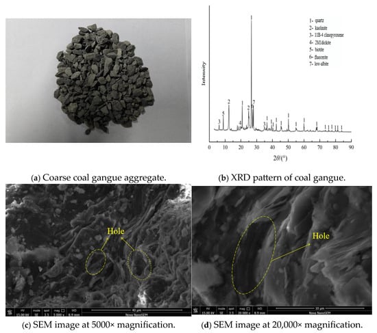
Figure 1.
Coal gangue.

Table 1.
The polymerization properties of coarse aggregates.
Fine Aggregate: River sand is employed as the natural fine aggregate in the experiment, with a fineness modulus of 2.8, meeting the requirements specified in the “Standard for Technical Requirements and Test Methods of Sand and Crushed Stone (or Gravel) for Ordinary Concrete” (JGJ 52-2006).
Water: Local tap water sourced from the laboratory is utilized as mixing water in the study, with all quality parameters conforming to the requirements of the “Standard of Water for Concrete” (JGJ 63-2006) [27].
Cement: Ordinary Portland cement (P·O 42.5) is deployed in the study, with a specific surface area of 340 m2/kg. All performance indicators meet the requirements of the “Common Portland Cement” (GB 175-2007) [28] standard.
Fly Ash: Fly ash is purchased from the local market. All performance indicators conform to the “Fly Ash Used for Cement and Concrete” (GB/T 1566-2017) [29] standard.
Water Reducer: A high-efficiency polycarboxylate-based superplasticizer with a water reduction rate of 25% is employed in the study. All physical and chemical properties fulfill the requirements specified in the “Concrete Admixtures” (GB 8076-2008) [30].
2.2. Proportion Design of Coal Gangue Concrete
According to the “Standard for Test Methods of Concrete Physical and Mechanical Properties” (GB/T 50081-2019) [31], prismatic specimens of dimensions 100 mm × 100 mm × 300 mm are used as compressive test specimens, with a total of four groups consisting of 60 specimens. The coal gangue replacement ratios for the groups are 0%, 20%, 40%, and 60%, designated as M0, M20, M40, and M60, respectively. The corresponding concrete mix proportions are presented in Table 2. Test specimens are prepared in accordance with the “Standard for Test Methods of Performance of Ordinary Concrete Mixtures” (GB/T 50080-2016) [32]. After molding, the test specimens are demolded following a 24 h stabilization period under standard conditions and subsequently cured in a curing chamber maintained at 20 ± 2 °C and a relative humidity of no less than 98% for 28 days. During the curing period, the appearance of the test specimens is monitored to ensure the absence of visible defects. Four days prior to reaching the 28-day curing age, the specimens are immersed in water maintained at 20 ± 2 °C for a period of 4 days, after which the specimens are taken out and the moisture on the surface of the specimens is gently wiped off. The axial compressive strength of each specimen group under 0 freeze–thaw cycles is subsequently determined in accordance with the “Standard for Test Methods of Concrete Physical and Mechanical Properties” (GB/T 50081-2019).

Table 2.
Mix proportion design of coal gangue concrete.
2.3. Freeze–Thaw Test
In accordance with the “Standard for Test Methods of Long-Term Performance and Durability of Concrete” (GB/T 50082-2024) [33], the freeze–thaw test is conducted using the rapid freezing method. Following completion of curing, the specimens are immersed in water until fully saturated and subsequently transferred to a freeze–thaw testing apparatus to initiate the freeze–thaw cycles. Considering that coal gangue concrete is mainly employed in above-ground and underground projects of coal mining enterprises, there are significant differences between the service environment of coal gangue concrete and that of conventional construction projects. Most above-ground and underground concrete structures in mining environments exhibit a service life significantly shorter than the 50-year design service life typical of conventional buildings. In view of the anticipated service duration and impact of environmental factors such as wet–dry alternation and freeze–thaw cycling, the maximum number of freeze–thaw cycles in this study is set at 80 [34].
The freeze–thaw tests are conducted by means of the LRHS-250B-LJS high-temperature and low-temperature alternating humidity test chamber manufactured by Shanghai Linpin Instrument Co., Ltd. (Shanghai, China). As shown in Figure 2. During each freeze–thaw cycle, the central temperature of the specimens reaches (−17 ± 2) °C at the end of the freezing stage, which lasted approximately 2 h. At the end of the thawing stage, the central temperature rises to (8 ± 2) °C, with the warming phase lasting about 1 h. Throughout the cycles, the temperature difference between the center and the surface of the specimens was consistently controlled within 28 °C.
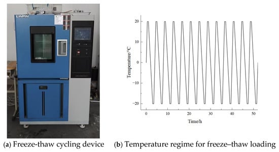
Figure 2.
Freeze–thaw test equipment and loading protocol.
Axial compressive tests are conducted after each group of specimens has completed 20, 40, and 60 freeze–thaw cycles, using the coal and rock rheological testing system developed by the Key Laboratory of Mine Filling Safety Mining National Mine Safety Administration, in accordance with the “Standard for Test Methods of Concrete Physical and Mechanical Properties” (GB/T 50081-2019), at a loading rate of 1 mm/min.
3. Results and Analysis
3.1. Compressive Stress–Strain Curves
The compression tests on samples of M0, M20, M40 and M60 with different freeze–thaw cycles are conducted using the coal and rock rheological test system equipment of the Key Laboratory of Mine Filling Mining National Mine Safety Administration. The stress–strain curves of the samples are collected. The specific stress–strain curves are shown in Figure 3.
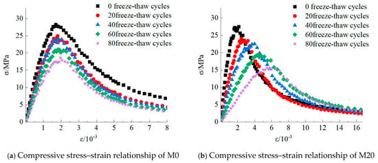
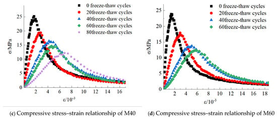
Figure 3.
Experimental results of compressive tests on coal gangue concrete.
Figure 3 presents the compressive stress–strain curves of coal gangue concrete specimens at various coal gangue replacement ratios following freeze–thaw cycling. Each curve represents the average of test results from three specimens within the same group. Among them, after 80 freeze–thaw cycles, the M60 group is unable to undergo axial compressive strength testing due to severe damage to the specimens. As shown in Figure 3a, for ordinary concrete, the axial compressive strength of the specimens gradually decreases with increasing freeze–thaw cycles. When the number of freeze–thaw cycles reaches 60, the compressive strength loss rate attains 25%, beyond which the concrete is considered no longer serviceable. As shown in Figure 3b–d, as the coal gangue replacement rate increases, the corresponding number of failed freeze–thaw cycles for coal gangue concrete decreases to 60, 40, and 40, respectively. It can be concluded that when coal gangue from the Halagou dump is used to produce coal gangue concrete, the gangue replacement rate should not exceed 20%, and the allowable number of freeze–thaw cycles under the condition should not surpass 60.
As shown in the figure, with increasing freeze–thaw cycles, the peak stress of each specimen group exhibits a decreasing trend, while the peak strain increases. Concurrently, the elastic modulus gradually decreases, and the overall shape of the stress–strain curve becomes progressively flatter. Under identical freeze–thaw cycles, as the coal gangue substitution ratio increases, the initial-stage depression behavior in concrete becomes increasingly pronounced. Due to the high water absorption rate of coal gangue, which generates greater freeze–thaw expansion pressure during the freeze–thaw process, the strength of coal gangue is lower than that of natural aggregates, resulting in more severe freeze–thaw damage and thus demonstrating a stronger compaction effect.
3.2. Elastic Modulus
In accordance with the “Standard for Test Methods of Concrete Physical and Mechanical Properties” (GB/T 50081-2019), the secant modulus derived from the stress range between 0 and 0.4 times the axial compressive strength (0.4 ) on the complete stress–strain curve is defined as the elastic modulus of concrete.
According to the relevant provisions of the “Code for Design of Concrete Structures”(GB 50010-2010) [35], the theoretical calculation of the elastic modulus of ordinary concrete is recommended to be carried out using the following formula:
In the formula, fcu represents the cube compressive strength of concrete in MPa, and Ec denotes the elastic modulus of concrete in MPa. The tested values of elastic modulus, theoretically calculated values, and the ratios of tested-to-theoretical values for each group are summarized in Table 3.

Table 3.
Measured and theoretically calculated values of elastic modulus for coal gangue concrete.
As shown in Table 3, the elastic modulus ratio of each concrete group decreases with increasing freeze–thaw cycles. After 80 freeze–thaw cycles, the elastic modulus ratios for M0, M20, M40, and M60 are reduced to 0.42, 0.12, 0.08, and 0.06, respectively. It is evident that under the combined influence of the coal gangue replacement ratio R and the number of freeze–thaw cycles N, the applicability of the code-recommended Formula (1) becomes progressively limited as both the replacement ratio and the number of cycles rise. The deviation between the calculated results and the actual experimental values also grows larger.
As illustrated in Figure 4, the average compressive strength exhibits a consistent decline with increasing freeze–thaw cycles. The relatively short error bars associated with each data point indicate minimal variability among the three replicate specimens under identical freeze–thaw conditions, demonstrating the high consistency and reliability of the experimental data obtained in this study.
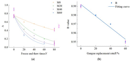
Figure 4.
Experimental data and fitting results of . (a) The relationship between and the number of freeze–thaw cycles. (b) The relationship between B and the substitution rate of coal gangue.
A certain correlation is considered to exist between the value of and the number of freeze–thaw cycles N as well as the coal gangue replacement ratio R. Initially, a fitting analysis was conducted with the number of freeze–thaw cycles as the independent variable. The fitting results are presented in Figure 3a, the pink arrows in the figure are error bars, indicating the existing errors. Yielding the following relationship between the modulus ratio and the number of freeze–thaw cycles (R2 = 0.96, RMSE = 0.02):
In Equation (2), B denotes the fitted parameter, with corresponding values for each concrete group presented in Figure 4b. By regressing B against the coal gangue replacement rate R as the independent variable, the following relationship with R is established:
In the proposed model, the fitting parameter B is not merely a mathematical constant but possesses explicit physical significance. It can be interpreted as a freeze–thaw sensitivity factor governing stiffness degradation. The value of B decreases with increasing gangue content (R), which physically indicates that gangue aggregate, due to its inherent high water absorption and low mechanical strength, generates greater internal expansion pressure and promotes more extensive microcrack development during freeze–thaw cycles. This mechanism significantly accelerates the degradation rate of the concrete’s macroscopic elastic modulus.
By substituting Equation (3) into Equation (2), the relationship between the elastic modulus Ec and the coal gangue replacement ratio R and the number of freeze–thaw cycles N can be derived as follows:
3.3. Peak Strain of Coal Gangue Concrete
The peak strain value corresponding to the peak stress in the stress–strain curve of coal gangue concrete is detailed in Table 4. As shown in the table, when the number of freeze–thaw cycles reaches 80, the peak strain of M0, M20, M40, and M60 increases by 11%, 203%, 305%, and 353%, respectively. It is obvious that the number of freeze–thaw cycles leads to a decreasing trend in the elastic modulus of coal gangue concrete. Upon reaching the maximum stress, concrete with a higher coal gangue replacement rate exhibits a greater degree of deformation.

Table 4.
Tested and calculated values of peak strain in coal gangue concrete.
According to the “Code for Design of Concrete Structures” GB 50010-2010, the formula for calculating the peak strain of ordinary concrete is as follows:
In the formula, represents the peak strain of concrete; denotes the axial compressive strength.
As illustrated in Figure 5a, the fitting is first conducted with the freeze–thaw cycle number R as the independent variable, resulting in Equation (6). Then, the fitting is carried out with the coal gangue replacement rate N as the independent variable and parameter A as the dependent variable, resulting in Equation (7). The corresponding fitting curve is displayed in Figure 5b.
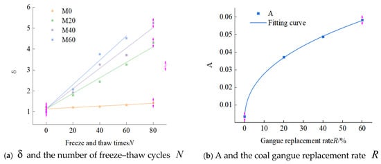
Figure 5.
Experimental and fitted results of .
Substituting Equations (6) and (7) into Equation (5) yields the analytical expression for the peak strain of coal gangue concrete under freeze–thaw cycling, as presented in Equation (8). The physical meaning of the fitting parameter A can be interpreted as the plastic deformation capacity enhancement coefficient. In Equation (7), A increases with increasing gangue content R. This quantitative relationship reflects the following physical mechanism: the interfacial transition zone (ITZ) between gangue aggregate and cement paste is a weak link in the material, and freeze–thaw cycles exacerbate damage there. Under uniaxial compression loading, these pre-existing microdefects promote the initiation and propagation of more extensive microcracks, causing the material to undergo greater irreversible plastic deformation before reaching peak stress.
3.4. Shape Parameter n of Coal Gangue Concrete in the Pre-Peak Elastoplastic Rising Stage
The parameters of the ascending section of the stress-strain curve of coal gangue concrete are shown in Table 5. The calculation model for the ascending section of the stress–strain curve of ordinary concrete, as given in GB 50010-2010 “Code for Design of Concrete Structures”, is as follows:
where , .

Table 5.
Parameters of the ascending segment in the stress–strain curve of coal gangue concrete.
The parameter n determines the shape of the rising segment of the stress–strain curve. Its physical nature is closely related to the material’s behavior as it transitions from linear elasticity to plastic hardening. With increasing freeze–thaw cycles N and gangue content R, the observed trend in the n value indicates a more developed microcrack system within the material, leading to a more pronounced nonlinear relationship between stress and strain. This intensifies the material’s nonlinear hardening characteristics. In the initial loading phase, greater resistance to microcrack closure due to freeze–thaw cycles and weak interfaces must be overcome, leading to earlier stable microcrack expansion.
3.5. Parameters α and β of the Post-Peak Plastic Deformation Descent Section of Coal Gangue Concrete
According to the “Code for Design of Concrete Structures” (GB 50010-2010), the calculation model for the descending portion of the stress–strain curve of ordinary concrete is as follows:
where β is a constant, taken as β = 2.0 for ordinary concrete; α is a parameter related to strength, taken as for ordinary concrete. Using Equation (5) as the analytical model, the descending segment of the experimental stress–strain curve was fitted, with parameter α shown in Figure 6 and parameter β shown in Figure 7.

Figure 6.
Parameter a of the descending segment in the stress–strain curve of coal gangue concrete α. (a) The relationship between the shape degradation coefficient α and the coal gangue substitution ratio R. (b) The relationship between the shape degradation coefficient α and the number of freeze–thaw cycles N. (c) The relationship between the shape degradation coefficient α and the axial compressive strength fc.
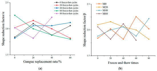
Figure 7.
Parameter b of the descending segment in the stress–strain curve of coal gangue concrete β. (a) The relationship between the shape decline coefficient β and the coal gangue substitution rate R. (b) The relationship between the shape decline coefficient β and the number of freeze–thaw cycles N.
As exhibited in Figure 6, the strength reduction factor α of coal gangue concrete is influenced by the coal gangue replacement ratio R and the number of freeze–thaw cycles N, and the axial compressive strength fc; while Figure 7 shows that the shape reduction factor β does not exhibit a significant correlation with either the coal gangue replacement ratio or the number of freeze–thaw cycles N.
As analyzed previously, under freeze–thaw conditions, the parameters of the descending section of the stress–strain curve for coal gangue concrete should be modified based on the calculation model for ordinary concrete, by incorporating the effects of the coal gangue replacement ratio R and the number of freeze–thaw cycles N. Therefore, it is recommended to use Equation (12) for calculating parameter α and Equation (13) for determining the value of parameter β.
Based on the above analysis, the following formula is recommended for calculating the stress–strain relationship of coal gangue concrete under freeze–thaw conditions.
4. Numerical Simulation Analysis
4.1. Model Establishment
Abaqus is an engineering simulation platform grounded in finite element analysis technology, which features comprehensive pre-processing and post-processing capabilities as well as robust nonlinear analysis functionality. It has been extensively employed in numerical simulation studies of concrete structures. The study conducts relevant simulation analysis based on the Abaqus platform. In Abaqus, three constitutive models are provided for simulating the material properties of concrete: the brittle fracture model, the distributed crack model, and the concrete damage plasticity (CDP) model. Among these models, the concrete plastic damage model (CDP) is capable of accurately capturing the mechanical behavior of concrete throughout the entire loading process. Therefore, this study adopts the CDP model as the primary tool for numerical analysis. The CDP model can accurately characterize the compressive crushing and tensile cracking behavior of concrete. The CDP model has been widely applied in the freeze–thaw simulation of concrete structures [36,37]. The strength and elastic modulus of coal gangue concrete are derived from experimental measurements. The Poisson ratio is set at 0.22. The plastic parameters are determined according to the recommended values reported in the literature [38], as specified in Table 6. For concrete-based materials, the expansion angle typically ranges between 30° and 40°. A value of 30° is selected as a relatively conservative choice, which is widely adopted in modeling both conventional concrete and recycled aggregate concrete. The dilation parameter is set to 0.1, which is the default value recommended by Abaqus documentation for concrete; this ensures numerical stability under tensile and compressive stress states and is therefore directly adopted in this study. For the ratio of uniaxial tensile strength to biaxial compressive strength (denoted as fb0/fc0), the typical range lies between 1.10 and 1.16. A value of 1.15 is chosen, consistent with both the majority of the published literature and the default settings in Abaqus, enabling accurate representation of concrete’s strength behavior under multiaxial stress conditions.

Table 6.
Material parameter values for the plastic damage model.
The three-dimensional finite element model of the concrete specimen is illustrated in Figure 8. The dimensions of the model are 100 mm × 100 mm × 300 mm. The compressive constitutive behavior of concrete is represented by a coal gangue concrete model that accounts for freeze–thaw effects, which is established through analytical results from Equations (14)–(16). The CDP parameters , , and required for numerical simulation are subsequently determined from the constitutive model. The tensile constitutive relationship is established according to the provisions specified in the “Code for Design of Concrete Structures” (GB 50010–2010). A C3D8R element is employed for the concrete, representing a three-dimensional linear brick element with reduced integration, and the mesh size is set to 10 mm. The model simulation is conducted employing a static, general analysis step with automatic time incrementation. The model utilizes rigid loading pads characterized by a high elastic modulus. The interaction between the rigid pads and the prismatic specimen is governed by a friction coefficient of 0.2. The upper and lower surfaces of the rigid pads are coupled with reference points 1 and 2, respectively, to facilitate the application of boundary conditions. The lower surface of the model is subjected to a fully fixed boundary condition, and the upper surface is the loading end. A downward vertical displacement load is applied, and the other two directions are fixed displacement constraints.
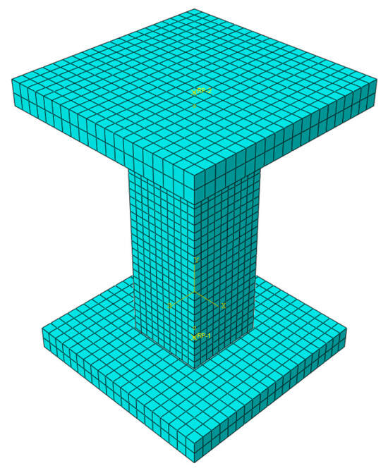
Figure 8.
Simulation model for uniaxial compressive strength test.
4.2. Analysis of Simulation Results
The ultimate strain was defined as the strain corresponding to the stress at 0.5fc on the descending branch of the concrete stress–strain curve, as specified in the code [35]. The failure mode contour plot of the longitudinal section of the concrete finite element model is examined to analyze the damage distribution.
As illustrated in Figure 9a, for ordinary concrete, the DAMAGEC (compressive damage) value of the concrete specimen shows a significant upward trend with increasing freeze–thaw cycles. The damaged region progressively expands and becomes more localized. Without any freeze–thaw cycles, the color map shows very little damage—almost zero—which is typical for normal concrete under compressive stress, as the specimen has not yet been affected by freeze–thaw damage. When the number of freeze–thaw cycles reaches 20, the regions exhibiting light green and yellow areas in the contour plot expand, indicating that the damage value begins to increase, and overall damage to the specimen becomes apparent. The damage is predominantly localized in the middle of the specimen, forming an elliptical or circular core damage area. The localization occurs due to a higher stress concentration in the mid-section under uniaxial compression, where repeated freeze–thaw exposure further aggravates microstructural deterioration. When the number of freeze–thaw cycles reaches 40, the yellow damage area expands further compared to the case at 20 cycles, with a noticeable shift toward orange in color. The damage value increases significantly, and the shape of the central high-damage zone becomes more clearly defined. After 60 freeze–thaw cycles, the damage area becomes highly significant, with a DAMAGEC value of 0.480 or higher. A substantial portion of the central region exhibits orange or red coloring, which indicates severe damage. When the number of freeze–thaw cycles reaches 80, the high-damage area in the center becomes smaller and more concentrated, with the color evolving into a distinct orange-red hue. In summary, for ordinary concrete, concrete damage exhibits a cumulative effect with freeze–thaw cycles. As the number of freeze–thaw cycles increases, internal damage accumulates, leading to a continuous increase in the DAMAGEC value. The damage area, initially scattered, gradually concentrates and expands in the middle of the specimen, ultimately forming a core area of high damage, which is consistent with the experimental results presented in Figure 3.
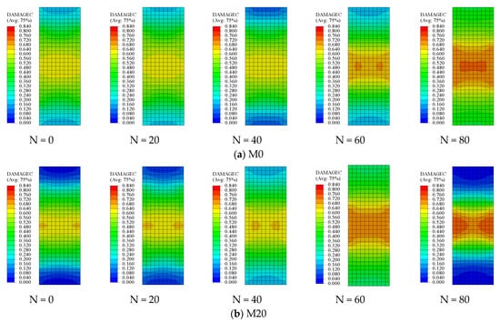
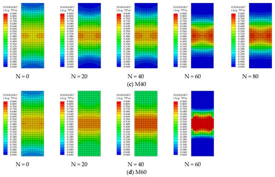
Figure 9.
Nephogram of compressive damage factor in concrete finite element model.
As the coal gangue replacement ratio increases, the concrete’s resistance to freeze–thaw damage decreases. As shown in Figure 9a, when the number of freeze–thaw cycles reaches 60, the central part of the concrete begins to show an orange color, which indicates that the DAMAGEC value in the central region reaches 0.64 (Figure 3). At 60 freeze–thaw cycles, the compressive strength of the concrete is 20.79 MPa, with a strength loss rate of 25%, which means the concrete no longer meets the service requirements. As shown in Figure 9b–d, with coal gangue replacement ratios of 20%, 40%, and 60%, the number of freeze–thaw cycles at which the concrete fails to meet the service requirements are 60, 40, and 40 cycles, respectively. The corresponding DAMAGEC values also show a significant increase at these cycle numbers. The numerical simulation results are consistent with the experimental results.
As shown in Figure 10a, in the initial state without freeze–thaw cycles (N = 0), concrete specimens exhibit relatively good load-bearing capacity under uniaxial compressive loading. The PEEQ values are primarily distributed within the low range of 0.00084–0.00168, and the color map displays a uniform distribution predominantly characterized by blue hues, with only minor plastic strain concentration observed in the upper-middle region of the specimens. The distribution pattern is consistent with the typical response characteristics of ordinary concrete under axial compression. As the number of freeze–thaw cycles increases to 20 and 40, material damage begins to become increasingly evident. The maximum PEEQ value gradually increases to the range of 0.00252–0.00420. The color map transitions from a uniform blue to green and yellow in some areas, indicating an expanding range of plastic strain distribution and progressive damage accumulation. This phase is considered the initial development stage of freeze–thaw damage, where irreversible deterioration of the microstructure begins. When the number of freeze–thaw cycles reaches 60 and 80, the damage accumulation effect becomes extremely significant. The peak PEEQ value sharply increases to approximately 0.00840. In the contour plot, extensive orange and red high-strain areas appear on the color map, concentrated in specific locations, exhibiting obvious strain localization. The pronounced strain localization indicates that the material has approached or reached its ultimate load-bearing capacity. The most prominent characteristic of the entire freeze–thaw process is the nonlinear accumulation of damage. For every additional 20 freeze–thaw cycles, the peak PEEQ value nearly doubles, indicating that the damage inflicted on concrete materials does not follow a simple linear superposition but instead exhibits a clear trend of accelerated deterioration. The detrimental effect of each freeze–thaw cycle in the later stages is significantly greater than that observed during the initial cycles. The phenomenon is closely related to the expansion of pores, the initiation and propagation of microcracks, and the formation of water migration pathways, ultimately leading to significant degradation of the macroscopic mechanical properties and a substantial reduction in its load-bearing capacity.
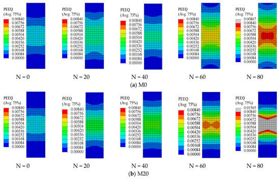
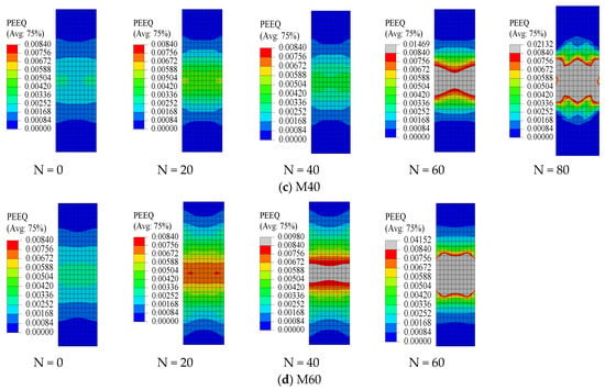
Figure 10.
Nephogram of equivalent plastic strain (PEEQ) in the concrete finite element model.
As the coal gangue content increases from 0% to 60%, the PEEQ nephograms exhibited the following consistent trends:
- (1)
- Aggravated overall plastic strain at the same number of freeze–thaw cycles N:
At low replacement ratios (0–20%), the strain remains relatively low and uniformly distributed even under higher numbers of freeze–thaw cycles. For instance, in the case of M0 at N = 80, the nephogram is dominated by gradients of blue to light blue, with minimal green or yellow zones, indicating moderate plastic deformation.
At higher replacement ratios (40–60%), the strain accumulation accelerates significantly. As shown in the nephogram for mix M60 at N = 80, the red areas (indicating high strain) became more pronounced and localized. When the number of freeze–thaw cycles reached 60 (N ≥ 60), ultra-high plastic strain zones (where PEEQ exceeded 0.0098) emerged in mix M40. Similarly, at N ≥ 40, mix M60 also exhibited such ultra-high plastic strain regions. The indicates that the concrete has undergone severe plastic deformation, and the specimen effectively lost its compressive load-bearing capacity. The high porosity and water absorption of coal gangue exacerbate internal pore expansion and cracking during freeze–thaw cycles, leading to reduced concrete strength and increased plastic deformation. Studies indicate that frost resistance deteriorates with increasing substitution ratio, as higher coal gangue content raises the amount of pore water, thereby intensifying freeze–thaw pressure. Additionally, elevated gangue content compromises the inherent compressive capacity of concrete, accelerating material degradation and strength loss.
- (2)
- Shift in Strain Concentration Trends
At lower replacement ratios (0–20%), as the number of freeze–thaw cycles (N) increased, the strain gradient was distributed more uniformly along the height of the specimen. Strain initiated from both ends (top and bottom) and gradually propagated inward. For example, in M0 under N = 40–60 loading conditions, the yellow band-like region is extensive and exhibits no distinct strain concentration.
In contrast, at higher replacement ratios (40–60%), strain localization initiates at an earlier stage and typically manifests as a ring-shaped or band-like region of high strain (red zone) in the mid-to-upper section of the specimen when N = 60–80. The central area corresponds to a gray ultra-high plastic strain zone, surrounded by blue regions indicative of low strain. This behavior is attributed to the increased gangue content, which promotes heterogeneous pore distribution and facilitates microcrack propagation. Under compressive loading, this results in localized stress concentration and enhanced plastic deformation. As gangue particles serve as weak interfaces within the matrix, the deformation mechanism transitions from uniform plasticity to localized strain concentration.
- (3)
- Accelerated Strain Evolution During Freeze–Thaw Cycles
For the 0% replacement ratio, significant strain (indicated by yellow-to-red transition) became apparent only after N = 40–60, whereas the strain distribution remained predominantly blue (indicating minimal strain) during the initial loading stages (N = 0–20). In comparison, at 60% replacement, distinct yellow bands emerged as early as N = 20, and rapidly evolved into red/gray-dominated patterns by N = 60–80. The color transition occurred earlier and more abruptly for the height. This acceleration is attributed to the inherent porosity of gangue, which absorbed more moisture, amplifying hydrostatic pressure and ice expansion during freezing. This progressively weakened the interfacial transition zone, resulting in reduced compressive strength and faster accumulation of plastic deformation at higher replacement rates.
- (4)
- Implications for Material Performance
At replacement ratios of 20% or lower, the freeze–thaw resistance is relatively well-balanced, and the strain development pattern closely resembles that of conventional concrete (M0). When the replacement ratio exceeds 30–40%, mechanical performance deteriorates significantly, as evidenced by the accelerated development of red and gray high-strain regions. These trends align closely with experimental results. When using gangue from Halagou Gully for concrete under freeze–thaw conditions, it is recommended that the coal gangue replacement ratio not exceed 20%, and the number of freeze–thaw cycles should be limited to 60 to ensure durability.
4.3. Fitting Analysis of Finite Element Model Data and Experimental Data
As shown in Table 7, in the axial compression simulation of the specimen model, the deviations between the simulated compressive strength and strain data and the experimental results were within 10%, demonstrating that the model effectively captures the mechanical behavior of coal gangue concrete after freeze–thaw cycles.

Table 7.
Comparison of simulated and experimental results for specimen compressive strength.
5. Conclusions
The study conducted freeze–thaw experiments on four groups of concrete specimens with different mix proportions, investigating the effects of the coal gangue replacement ratio and the number of freeze–thaw cycles on the mechanical properties of coal gangue concrete. Based on experimental analysis, the compressive damage evolution parameters specified in the code were modified, and a constitutive model for coal gangue concrete under freeze–thaw conditions was established. Furthermore, the applicability of the constitutive relationship was validated through finite element simulations.
- (1)
- As the number of freeze–thaw cycles increased, the mechanical properties of all groups of coal gangue concrete deteriorated to varying degrees. When the number of freeze–thaw cycles increased from 0 to 80, the peak stress of mix M0 decreased by 35%, the peak strain increased by 10.8%, and the elastic modulus decreased by 49.2%. For mix M20, the peak stress decreased by 41.78%, the peak strain increased by 203.4%, and the elastic modulus decreased by 86.2%. Mix M40 exhibited a 51.1% reduction in peak stress, a 304.9% increase in peak strain, and a 92% decrease in elastic modulus. Mix M60 was severely damaged and could not be tested for axial compressive strength. Under the same number of freeze–thaw cycles, the concave effect in the stress–strain curves became more pronounced with higher coal gangue replacement ratios. This is primarily attributed to the higher water absorption of coal gangue, which leads to greater freeze–thaw stress compared to ordinary concrete, as well as the inferior mechanical properties and reduced resistance to freeze–thaw damage of coal gangue.
- (2)
- When using coal gangue from Halagou Gully for concrete preparation under freeze–thaw conditions, a 20% replacement ratio is identified as the optimal value. At this ratio, the strength loss rate due to freeze–thaw action is closest to that of ordinary concrete, meeting performance requirements while effectively utilizing gangue waste. This represents a viable pathway for the resource utilization of coal gangue.
- (3)
- As the coal gangue replacement ratio and the number of freeze–thaw cycles increase, the constitutive relationship for concrete specified in the Code for Design of Concrete Structures (GB 50010-2010) becomes increasingly inadequate. Therefore, the compressive damage evolution parameters in the code were modified, and a constitutive model for coal gangue concrete under freeze–thaw conditions was established. This model can be applied in the structural design of coal gangue concrete.
- (4)
- The constitutive relationship proposed in this study can be integrated with the Concrete Damaged Plasticity (CDP) model in Abaqus. It effectively simulates the uniaxial compressive behavior of coal gangue concrete after freeze–thaw action and accurately reflects the stress development and damage state of the concrete during loading.
- (5)
- Under freeze–thaw (F-T) cycles, the deterioration of coal gangue concrete (CGC) is governed by a synergistic mechanism involving highly absorbent coal gangue aggregates and the resulting low-temperature expansion. The inherent porosity of coal gangue introduces additional water reservoirs within the concrete matrix, which generate substantial internal expansive pressure during freezing. This process preferentially degrades the relatively weak interfacial transition zone (ITZ) between the coal gangue aggregates and the cement paste. Macroscopically, this degradation manifests as an accelerated reduction in compressive strength and elastic modulus, a notable increase in peak strain, and a more brittle post-peak response.
6. Discussion
The constitutive model proposed in this study is constructed based on the material properties, load conditions and environmental parameters in a specific engineering context. The parameter calibration, mechanical behavior fitting and verification processes all rely on the data in this engineering scenario. From the perspective of the model’s applicability boundary, this model has not yet considered the possible differences in key variables in different engineering scenarios. Therefore, the application scope of the current model has clear limitations and can only provide theoretical support for structural design, performance evaluation, or failure analysis under the same engineering background. In view of the limitations of the current model, subsequent research will focus on “constructing a more universal and complete constitutive model”.
Author Contributions
Conceptualization, G.G. and D.F.; Methodology, M.G. and Z.H.; Software, J.C.; Validation, J.C.; Formal analysis, C.G.; Investigation, C.G.; Resources, M.G.; Data curation, C.G. and Z.G.; Writing—original draft, J.C. and C.G.; Writing—review and editing, Z.H. and M.L.; Visualization, M.L. and Z.G.; Supervision, M.G. and Z.H.; Project administration, M.G.; Funding acquisition, M.G. All authors have read and agreed to the published version of the manuscript.
Funding
This research was funded by National Key R&D Program of China (2018YFC0604700), National Natural Science Foundation of China (Grant No. 51474134), Funding for basic scientific research business of central universities (Grant No. 3142022002).
Data Availability Statement
The original contributions presented in this study are included in the article. Further inquiries can be directed to the corresponding authors.
Conflicts of Interest
Author Guojun Gao was employed by the company Guoneng Shendong Ordos New Energy Technology Development Co., Ltd. Author Donglin Fan was employed by the company Shendong Coal Technology Research Institute. The remaining authors declare that the research was conducted in the absence of any commercial or financial relationships that could be construed as a potential conflict of interest.
References
- Liang, Y.; Liang, H.; Zhu, S. Mercury emission from spontaneously ignited coal gangue hill in Wuda coalfield, Inner Mongolia, China. Fuel 2016, 182, 525–530. [Google Scholar] [CrossRef]
- Liu, X.; Liang, C.; Qian, J.; Li, X.; Li, X.; Li, B.; Xu, G.; Zhou, B. Research on wireless monitoring system for internal temperature field of coal gangue mountain. Case Stud. Therm. Eng. 2025, 66, 105742. [Google Scholar] [CrossRef]
- Li, Y.; Liu, S.; Guan, X. Multitechnique investigation of concrete with coal gangue. Constr. Build. Mater. 2021, 301, 124114. [Google Scholar] [CrossRef]
- Cheng, L.; Zhao, L.; Cheng, L.; Gao, Y.; Guo, H.; Che, Y.; Fu, H. Research Progress of Concrete Preparation Based on Solid Waste Properties of Coal Gangue. Sustainability 2025, 17, 2007. [Google Scholar] [CrossRef]
- Jin, H.; Xu, G.; Han, W.; Gao, L.; Li, Z. Sustainable development of energy systems for western China. Energy 2009, 35, 4313–4318. [Google Scholar] [CrossRef]
- Liu, M.; Lu, J.; Ming, P.; Yu, J. Study on the fracture properties of concrete considering salt-freeze-thaw damage. Constr. Build. Mater. 2024, 448, 138147. [Google Scholar] [CrossRef]
- Luo, D.; Wang, Y.; Zhang, S.; Niu, D.; Song, Z. Frost Resistance of Coal Gangue Aggregate Concrete Modified by Steel Fiber and Slag Powder. Appl. Sci. 2020, 10, 3229. [Google Scholar] [CrossRef]
- Li, J.; Luo, J.; Chen, L.; Fan, X.; Zhu, Y.; Wang, X. Axial-compression performance and numerical-simulation analysis of steel tube coal gangue concrete column. J. Constr. Steel Res. 2024, 216, 108612. [Google Scholar] [CrossRef]
- Gao, S.; Zhao, G.; Guo, L.; Zhou, L.; Yuan, K. Utilization of coal gangue as coarse aggregates in structural concrete. Constr. Build. Mater. 2020, 268, 121212. [Google Scholar] [CrossRef]
- Cong, X.; Lu, S.; Yao, Y.; Wang, Z. Fabrication and characterization of self-ignition coal gangue autoclaved aerated concrete. Mater. Des. 2016, 97, 155–162. [Google Scholar] [CrossRef]
- Dong, Z.; Xia, J.; Fan, C.; Cao, J. Activity of calcined coal gangue fine aggregate and its effect on the mechanical behavior of cement mortar. Constr. Build. Mater. 2015, 100, 63–69. [Google Scholar] [CrossRef]
- Xiao, M.; Ju, F.; He, Z.-Q. Research on shotcrete in mine using non-activated waste coal gangue aggregate. J. Clean. Prod. 2020, 259, 120810. [Google Scholar] [CrossRef]
- Karimaei, M.; Dabbaghi, F.; Sadeghi-Nik, A.; Dehestani, M. Mechanical performance of green concrete produced with untreated coal waste aggregates. Constr. Build. Mater. 2020, 233, 117264. [Google Scholar] [CrossRef]
- Wu, C.; Zhang, C.; Li, J.; Wang, X.; Jiang, W.; Yang, S.; Wang, W. A sustainable low-carbon pervious concrete using modified coal gangue aggregates based on ITZ enhancement. J. Clean. Prod. 2022, 377, 134310. [Google Scholar] [CrossRef]
- Zhang, T.; Wen, Q.; Gao, S.; Tang, J. Comparative study on mechanical and environmental properties of coal gangue sand concrete. Constr. Build. Mater. 2023, 400, 132646. [Google Scholar] [CrossRef]
- Wang, J.; Chen, J.; Liu, M. Theoretical model for CFRP-confined spontaneous combustion gangue coarse aggregate concrete-filled steel tube stub columns under axial compression. Constr. Build. Mater. 2024, 415, 135113. [Google Scholar] [CrossRef]
- Xu, Z.; Wu, J.; Zhao, M.; Bai, Z.; Wang, K.; Miao, J.; Tan, Z. Mechanical and microscopic properties of fiber-reinforced coal gangue-based geopolymer concrete. Nanotechnol. Rev. 2022, 11, 526–543. [Google Scholar] [CrossRef]
- Qiu, J.; Zhang, R.; Guan, X.; Cheng, K.; Gao, Y.; Xiao, Z. Deterioration characteristics of coal gangue concrete under the combined action of cyclic loading and freeze-thaw cycles. J. Build. Eng. 2022, 60, 105165. [Google Scholar] [CrossRef]
- Wang, W.; Wang, Y.; Chen, Q.; Liu, Y.; Zhang, Y.; Ma, G.; Duan, P. Bond properties of basalt fiber reinforced polymer (BFRP) bars in recycled aggregate thermal insulation concrete under freeze–thaw cycles. Constr. Build. Mater. 2022, 329, 127197. [Google Scholar] [CrossRef]
- Zhang, Z.; Zhang, Z.; Wang, X.; Zhou, C. Dynamic and static interfacial bonding properties of CFRP-concrete subjected to freeze–thaw cycles. In Structures; Elsevier: Amsterdam, The Netherlands, 2022; Volume 37, pp. 947–959. [Google Scholar] [CrossRef]
- Chen, J.; Zhao, C.; Liu, Q.; Shi, X.; Sun, Z. Investigation on frost heaving stress (FHS) of porous cement concrete exposed to freeze-thaw cycles. Cold Reg. Sci. Technol. 2023, 205, 103694. [Google Scholar] [CrossRef]
- Wang, Y.; Liu, Z.; Zhang, B.; Fu, K. A time-dependent diffusive model for the simulation of chloride penetration in concrete considering the effect of natural salt freeze-thaw cycles. Cold Reg. Sci. Technol. 2022, 201, 103622. [Google Scholar] [CrossRef]
- Scherer, G.W. Crystallization in pores. Cem. Concr. Res. 1999, 29, 1347–1358. [Google Scholar] [CrossRef]
- Zuber, B.; Marchand, J. Modeling the deterioration of hydrated cement systems exposed to frost action. Cem. Concr. Res. 2000, 30, 1929–1939. [Google Scholar] [CrossRef]
- JGJ 52-2006; Ministry of Construction of the People’s Republic of China. Standard for Quality and Testing Methods of Sand and Crushed Stone for Ordinary Concrete. China Architecture & Building Press: Beijing, China, 2006. (In Chinese)
- GB/T 14685-2011; PRC National Standard. Specification of Pebble and Crushed Stone for Building. The National Cement Standardization Technical Committee (SAC/TC 184): Beijing, China, 2011.
- JGJ 63-2006; Ministry of Construction of the People’s Republic of China. Standard of Water for Concrete. China Architecture & Building Press: Beijing, China, 2006. (In Chinese)
- GB 175-2007; PRC National Standard. Common Portland Cement. The National Cement Standardization Technical Committee (SAC/TC 184): Beijing, China, 2007.
- GB/T 1596-2017; General Administration of Quality Supervision; Inspection and Quarantine of the People’s Republic of China and National Standardization Administration. Fly Ash Used for Cement and Concrete. Standards Press of China: Beijing, China, 2017. (In Chinese)
- GB 8076-2008; General Administration of Quality Supervision; Inspection and Quarantine of the People’s Republic of China and National Standardization Administration. Concrete Admixtures. Standards Press of China: Beijing, China, 2009. (In Chinese)
- GB/T 50081-2019; Ministry of Housing and Urban-Rural Development of the People’s Republic of China; State Administration for Market Regulation. Standard for Test Methods of Concrete Physical and Mechanical Properties. China Architecture & Building Press: Beijing, China, 2019. (In Chinese)
- GB/T 50080-2016; Standard for Test Methods of Performance of Ordinary Concrete Mixtures. China Architecture & Building Press: Beijing, China, 2016.
- GB/T 50082-2024; Ministry of Housing and Urban-Rural Development of the People’s Republic of China; State Administration for Market Regulation. Standard for Test Methods of Long-Term Performance and Durability of Concrete. China Architecture & Building Press: Beijing, China, 2024. (In Chinese)
- Qian, Z.K. Experimental Study on Mechanical Properties of Coal Gangue Concrete after Freeze-Thaw in Northern Shaanxi Mining Area. Master’s Thesis, Xi’an University of Architecture and Technology, Xi’an, China, 2023. [Google Scholar]
- GB/T 50010-2010; Ministry of Construction of the People’s Republic of China. Code for Design of Concrete Structures. China Architecture & Building Press: Beijing, China, 2011. (In Chinese)
- Wang, X.; Zhang, K.; Guo, J.; Wei, R.; Zhang, Z. Study on the Performance Degradation of Concrete Under Freeze-thaw Cycles Based on Mesoscopic Mechanical Models. Mod. Tunn. Technol. 2024, 61, 209–218. [Google Scholar] [CrossRef]
- Zhang, Z.; Feng, C.; Jiang, T.; Zhang, Y. Numerical simulation study on the freeze-thaw performance of recycled concrete based on ABAQUS. J. Chang. Inst. Technol. 2020, 21, 5–11. [Google Scholar] [CrossRef]
- Zhao, W.P.; Zhong, L.; Zhang, K.; Su, Z.; Xu, Y.; Chen, J. Experimental study and numerical simulation on bond performance of reinforced coal gangue concrete. J. Harbin Inst. Technol. 2025, 1–16. [Google Scholar]
Disclaimer/Publisher’s Note: The statements, opinions and data contained in all publications are solely those of the individual author(s) and contributor(s) and not of MDPI and/or the editor(s). MDPI and/or the editor(s) disclaim responsibility for any injury to people or property resulting from any ideas, methods, instructions or products referred to in the content. |
© 2025 by the authors. Licensee MDPI, Basel, Switzerland. This article is an open access article distributed under the terms and conditions of the Creative Commons Attribution (CC BY) license (https://creativecommons.org/licenses/by/4.0/).