Abstract
Ozone treatment in the food and horticulture product capitalization sectors is widely acknowledged as completely safe for human use, in accordance with the most recent rules of the relevant authorities. Ozone-generating devices for research and education are known to allow the introduction of ozone gas for many uses, especially in food and agricultural applications. Despite their usefulness, their high cost prevents them from being widely available in research and educational institutions in underdeveloped nations, limiting practical training and the development of local applications to support the capacities of the food and agriculture sectors. In this study a device was constructed to generate ozone (O3) using the high-voltage principal circuit. An Arduino board was used to accomplish the control operation. An MQ-131 ozone sensor was utilized to measure the ozone concentration with a measuring unit of (%); however, the detecting range of the MQ-131 sensor is 10~1000 ppb, so in the present study, a formula to covert the measuring units between ppm and (%) for the concentration of the generated ozone (Y) as (Y, %) = 0.0333 × (Y, ppm) was presented. Different ozone concentrations are generated by varying the high voltage level from 20 to 35 kV with an increment of 5 kV and flow rate variations of 1.5, 2, 2.5, and 3 L/min. It was found that ozone concentration increases with increasing applied high voltage and decreases with increasing oxygen flow rate at a fixed applied high voltage. This study uses experimental data in a multiple linear regression analysis to predict ozone concentration based on levels of high voltage and oxygen flow rate, with a coefficient of determination of 0.7686 using a testing dataset. The findings provide evidence of the viability of constructing an inexpensive ozone generator with inexpensive parts, thereby promoting sustainable technological advancement. Drawing from our research, we can highlight the educational value and cost-effective benefits of employing an ozone-generating device, which can be used to produce ozone for a variety of purposes.
1. Introduction
Despite its instability, ozone is a beneficial chemical [1]. In contrast to regular oxygen molecules, which comprise two oxygen atoms (O2), ozone is a triatomic form of oxygen, consisting of three oxygen atoms (O3). Ozone is a colorless, unstable gas with a distinct scent. When air in the atmosphere is exposed to a high-energy source, like ultraviolet radiation or a high-voltage electrical discharge, ozone is typically produced [2]. The amount of ozone found in nature is only sub-ppm. Ozone must be artificially manufactured in a machine to obtain large quantities [3]. Such machines are called ozone generators, devices that produce ozone by corona discharge [1]. Ozone is highly unstable and decomposes quickly into oxygen at room temperature [4], so it must be manufactured on-site for immediate use [5]. Ozone (O3), which is known for its powerful oxidizing powers, is utilized extensively for ozone treatment in the food and horticulture product capitalization sectors. This is entirely safe for human use based on the most recent rules of the relevant authorities [6].
Although various aspects of ozone production have been examined by several studies [7,8,9], the production of ozone is hindered by high operating and capital costs. To enable its wider use, particularly in small communities, these obstacles must be removed [10]. Even if ozone-creation devices are beneficial, their high cost keeps them from being widely accessible at research and educational institutions in developing countries, which restricts the development of local applications and hands-on training to strengthen the capacities of the food and agriculture sectors. However, rapid growth in technological improvement have led to the creation of several electronic devices and parts that have brought numerous significant benefits to society by making our life easier [11]. Additionally, during the past ten years, a growing number of businesses have begun to manufacture inexpensive sensors or even entire sensor systems that come with supporting parts (such as enclosures, power supplies, hardware, and software for data handling). As a result, it makes sense to work on creating ozone production devices and measuring methods that are also far less expensive than official measurement equipment [12].
The electrode configurations, dielectric material, chamber geometry, power source design, gas type (dry air or oxygen), input gas flow rate, and operation pressure were all examined by El-Mashede et al. [9] in their assessment of the ozone generator’s architecture for ozone production. Nowadays, air or oxygen gas passing through a high-voltage electrical discharge is the most popular method for producing ozone [5,13], and this called the corona discharge method [2]. In the corona discharge method, a high-voltage electrical field is created inside corona discharge tube, which ionizes oxygen molecules and eventually produces ozone [14], Figure 1. However, the high-energy discharge breaks molecular oxygen up into atomic oxygen radicals, which then spontaneously join molecular oxygen to produce ozone molecules [15]. Furthermore, according to Wang et al. [2], oxygen molecules are broken apart as they travel through an electrical field, creating extremely active atomic oxygen radicals that can join with intact oxygen molecules to make ozone. However, an oxygen molecule (O2) absorbs an electron (e−) and splits into two oxygen atoms (2O) as O2 + e− → 2O then, each oxygen atom (O) interacts with an oxygen molecule to produce ozone (O3) as 2O + 2O2 → 2O3. Additionally, the corona discharge method has been widely used to produce significant amounts of ozone [2]. Generally, numerous variables, such as ozone’s shape (gas or liquid), concentration, exposure duration, microbial species, and food properties, affect ozone’s effectiveness against dormant microorganisms [16].
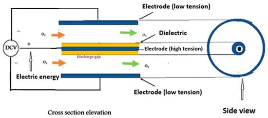
Figure 1.
Ozone generation process.
Ozone (O3), a highly reactive form of oxygen, is well known for its potent oxidizing capabilities and has a wide range of uses in the purification of air and water, according to Goyal [17]. The design, construction, and testing of a small-scale ozone generator that uses a high-voltage discharge mechanism to produce ozone are presented in this study. The study examines the generator’s fundamental ideas, circuit layout, and functional features before offering insights into its effectiveness, drawbacks, and room for development.
Fahrudin et al. [18] developed an ozone sterilization device based on microcontrollers. The designed system consists of an ozone gas chamber container, ozone gas metering devices, a neon sign transformer, and a corona electrode. After that, a corona electrode and neon sign transformer are put together to create an ozone generator that operates on the corona discharge principle. The microcontroller system regulates the use of ozone generators. Ozone generators, which are contained in a chamber and include ozone gas indicators, produce ozone gas. A study by Nehari et al. [19] described a low-cost solution for disinfecting a food storage area that included a photovoltaic panel, an ozone generator, and a power source. A laboratory-developed photovoltaic energy system powers the “ozone-supply generator” system. Moreover, pilot ozonation systems were described by de Carvalho Costa et al. [10]. However, a rotameter attached to the apparatus allows the ozone generator to work with varying oxygen fluxes, which range from 0 to 5.0 L O2/min. For large-scale applications, the study provides valuable insights into configuring and managing ozonation systems to optimize their efficacy and scalability.
Technologies based on ozone have proven successful in a variety of industrial settings. Ozone’s versatility as a beneficial treatment for food and agricultural products makes it particularly attractive for their preservation [20,21]. Moreover, the use of ozone in food processing activities is expected to contribute to the development of better and more ecologically friendly food systems, as ozone application techniques continue to be refined via research and technology improvements [22]. As a result, creative methods for building an ozone generator system with inexpensive components and evaluating the system’s viability and sustainability as a cost-effective option for small-scale agricultural and food applications, research, and teaching were the objectives of this study.
2. Materials and Methods
The study’s goal was to create a working prototype of an ozone (O3) generator utilizing inexpensive parts. The apparatus was constructed using an air compressor that delivers air at varying flow rates to add oxygen, in addition to oxygen from a water analyzer (electrolyzer). Moreover, a high-voltage unit that produced O3 was included. An Arduino board with sensors attached was used to accomplish the control operation. To finish the device, a stainless-steel tube and other basic components were utilized.
2.1. Components of the Developed Ozone Generator
The ozone generator consists of three central units (ozone production unit, power unit, and measurement and control unit) as shown in Figure 2. However, the block diagram of the working flow of the developed ozone generator setup is depicted in Figure 3.
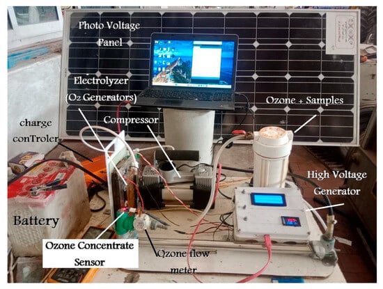
Figure 2.
The ozone generator consists of three units (ozone production unit, power unit, and measurement and control unit).
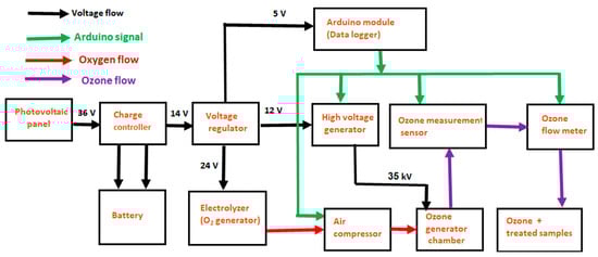
Figure 3.
The block diagram of the working flow, indicating Arduino signal, oxygen flow, and ozone flow of the developed ozone generator.
In the ozone production unit, ozone is produced by passing oxygen (O2) through an electrical discharge, which splits the oxygen molecules into single atoms that combine to form ozone (O3). This is called a corona discharge, which uses a high voltage between electrodes to ionize the gas. A voltage booster from 12 V to 35 kV was used. The reactor was constructed using a cylindrical electrode configuration. The Arduino module was used to control both the high voltage level and the compressor motor speed (Figure 4). An ozone gas sensor (MQ-131) Zhengzhou Winsen Electronics Technology Co., Ltd, (No.299, Jinsuo Road, National Hi-Tech Zone, Zhengzhou, China) [23] was connected to the Arduino module [24] and could be used to measure the ozone concentration in the chamber [25], which is used in the ozone generator, and which generates ozone from the oxygen in the surrounding air. The ozone sensor MQ-131 is connected to the Arduino module, as shown in Figure 4. The MQ-131 ozone sensor uses a metallic oxide semiconductor as its sensitive material because of its strong conductivity in clean air. When ozone gas is present, the conductivity of the sensor falls as the concentration of the gas rises. The MQ-131 sensor can be used as a portable ozone concentration detector in addition to being an industrial or home ozone concentration alert. The MQ-131 ozone sensor is long-lasting, simple to use, and adaptable enough to be linked to a microcontroller for a range of uses [26]. Additionally, the ozone flow rate meter was also connected to the Arduino module, which was used to measure the ozone flow rate. The details and the specifications of the MQ-131 are seen in the ozone gas sensor manual [23].
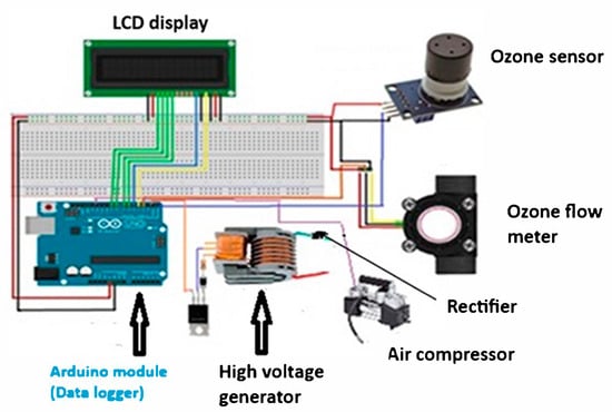
Figure 4.
Control unit (Arduino module, ozone sensor, high voltage generator, and ozone flow rate meter).
A photovoltaic panel was used to generate the electrical energy required for the system to operate. Excess energy is stored in a battery for use when the photovoltaic panel is not generating power. A voltage regulator, which takes electrical energy from the photovoltaic panel and battery, produces 5 V to power the Arduino module. It also produces 24 V to power the water analyzer unit for oxygen production. In this study, a high-voltage generator (Figure 4) was used to raise the potential difference from 12 V to 35 kV with a frequency higher than 1 kHz.
Electrolyzer Unit (O2 Generator)
One promising approach for producing green hydrogen and oxygen using renewable energy is water electrolysis [27,28]. An electrolyzer unit (O2 generator) consisting of 11 cells was used, as shown in Figure 5. The cells were made from stainless steel grade 310 plates with tabs on one end (anode and cathode electrodes) with a thickness of 0.9 mm and a surface area of 200 cm2, with an activity surface area of (7 × 16 cm), or 100 cm2. The electrodes, which were separated by a rubber sheet of 2 mm thickness, were placed between the cells. A stainless-steel metal sheet was chosen for its corrosion resistance to caustic electrolyte and long-lasting value. The electrodes separated by a rubber sheet and assembled between two shelter plastic sheets (160 × 240 × 10 mm) by 10 stainless steel screw was recapping with polystyrene tube. Two clusters electrode plates were placed—11 for the anode and 11 for the cathode. The hydrogen remains separate from the bubbles, which were produced from the positive electrode (anode) and exit on the opposite side.
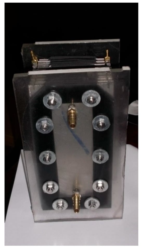
Figure 5.
The electrolyzer unit (O2 generator).
2.2. Calibration of the Arduino Ozone Sensor
The MQ-131 sensor is highly sensitive to ozone gas. It uses a semiconducting metal oxide as the sensing material, which exhibits high conductivity in clean air, while its conductivity decreases in the presence of ozone gas, with the decrease varying as the ozone concentration increases. The sensor can convert these conductivity changes into an output signal [23] corresponding to the gas concentration using an Arduino board, Manufacturer: Arduino, Genoa, Italy. The detection range of MQ-131 sensor ranges from 10~1000 ppb [23].
To calibrate the Arduino ozone sensor, MQ-131, it was exposed to a known, clean-air environment to obtain a baseline resistance value (R0), which depends on temperature and humidity. The sensor was then exposed to various known ozone concentrations using the portable commercial multi-function ozone analyzer, O3 ozone meter, which is used for air quality detection using a smart sensor, and this meter presents air pollution parameters. The calibration was implemented in the Arduino code to convert ozone sensor readings into ozone concentration percentage. Figure 6 shows the effect of ozone concentration (ppm) on volt RL, while Figure 7 shows the relationship between ozone concentration (ppm) and percentage of ozone concentration. Based on Figure 7, the formula to covert the measuring units between ppm and (%) for the concentration of the generated ozone (Y) is represented as (Y, %) = 0.0333 × (Y, ppm).
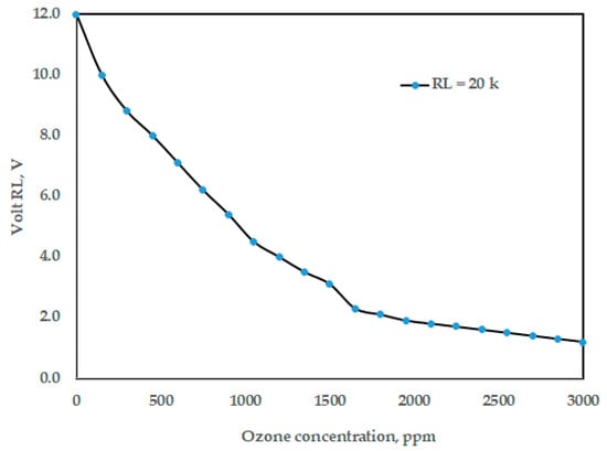
Figure 6.
The effect of ozone concentration (ppm) on volt RL.
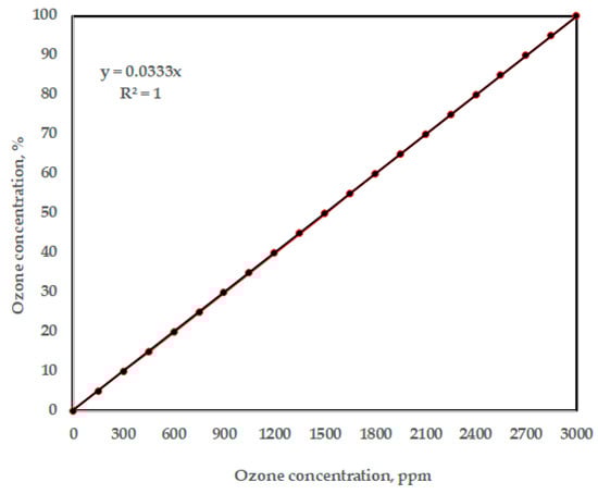
Figure 7.
The relationship between ozone concentration (ppm) and ozone concentration (%).
2.3. Experimental Procedure
The experimental process depended on the variation in the generated ozone concentration, which was achieved in this study by adjusting the high voltage level between 20 and 35 kV and the oxygen flow rate to various levels of 1.5, 2.0, 2.5, and 3.0 L/min. The actions listed below were taken:
- Decide on a single oxygen flow rate, such as 1.5 L/min.
- Change the high voltage level in predetermined increments (20, 25, 30, and 35 kV).
- Before recording the ozone concentration, let the system stabilize for each high voltage level.
- For the remaining oxygen flow rates (2.0, 2.5, and 3.0 L/min), repeat the procedure.
The total number of treatments is 16; however, the high voltage and oxygen flow rate combinations used to evaluate the effect of these parameters on ozone concentration and the treatment symbols are shown in Table 1. However, each treatment was reported three times.

Table 1.
The high voltage and oxygen flow rate combinations used to evaluate the effect of these parameters on ozone concentration.
To see how ozone concentration varies with changes in the high voltage and oxygen flow rate, the obtained data of ozone concentration were analyzed and plotted for each treatment combination. An Arduino based on the principles of pulse width modulation (PWM) [9,29,30,31] was used to manage the variation of the oxygen flow rate. However, the system diagram in Figure 8 shows the proposed self-excited high-voltage generator to supply the high voltage to the ozone generator tube. It primarily consists of a 12-V power source, a voltage level controller, a self-excited oscillating voltage booster, and a voltage multiplier.
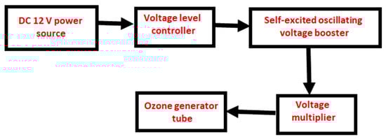
Figure 8.
System diagram of the proposed high-voltage generator to supply the high voltage to the ozone generator tube.
The voltage level controller controls the voltage from the power source within a controlled output range of 0 to 12 V. A flyback transformer is used in this study. The self-excited oscillating voltage booster has a push–pull converter structure. It takes the DC voltage from the voltage level controller in this study and uses an Arduino PWM technique. Pulse Width Modulation (PWM) is a technique for obtaining analog results using digital means. Digital control is used to create a square wave, a signal that oscillates between on and off. This on/off pattern simulates the voltage between full voltage and off voltage (0 V) by varying the signals on time relative to its off time. The duration of this “on time” is called the pulse width. To obtain variable analog values, you can change or modify the pulse width. If you repeat this on/off pattern quickly enough, the result will be as if the signal is a constant voltage between 0 Vcc, controlling the output voltage, and drives the power transistor using self-excited oscillation. Thus, the DC voltage is therefore transformed into AC. A high-frequency transformer is then used to increase the voltage. The voltage multiplier, instead of an active-type voltage booster to lower cost and volume, converts the AC from the high-frequency transformer into a DC potential. Then, the output voltage of the voltage multiplier is supplied to the ozone generator tube. In Figure 9, the main power circuit of the proposed high-voltage generator can be seen to supply high-voltage to the ozone generator. However, Shen and Liang [32] described similar circuit for self-excited high-voltage generator for the damping force of an electrorheological (ER) fluid shock absorber.
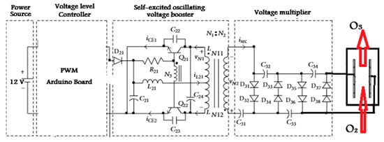
Figure 9.
Main power circuit of the proposed high-voltage generator to supply high-voltage to the ozone generator (C means capacitor and the other symbols are related to electronic parts).
3. Results and Discussion
The most common method of ozone generation is the corona discharge method [33], as shown in Figure 1. By applying a strong electric charge to a dielectric surface and producing a high voltage electric field, the corona discharge process produces O3 [34]. Oxygen molecules (O2) are caused to dissociate into individual oxygen atoms (O) by this field. These atoms subsequently rejoin with other O2 molecules to produce O3. The efficiency of the process is affected by a number of variables, such as the applied voltage, the properties of the dielectric material, and the operating conditions, such as temperature and pressure. Because of its efficiency in producing O3 at comparatively cheap prices and its adaptability to a range of applications requiring controlled O3 production, this technology is widely employed. When fed dry air, corona discharge ozone generators generate 1% to 4% of ozone. However, the ozone concentration increases to 6% to 14% when pure oxygen (93 ± 3%) is used as the input gas [35,36]. In the present study, the oxygen was created from a water analyzer, and it was mixed with ambient air; then, the air compressor delivers oxygen into the ozone generator. If an air compressor does not exist, oxygen from the water analyzer will only be delivered.
For the constructed system to be evaluated, the O3 concentration must be measured accurately. In this study, an MQ-131 ozone concentration sensor connected to an Arduino microcontroller was used. Using pulse width modulation (PWM) technology, the Arduino controls the high voltage levels from 20 to 35 kV, controlling the air compressor rotation speed and, in turn, controls the oxygen flow rate from 1.5 to 3.0 L/min. To stabilize the ozone concentration at the corona effect generator output, care must be taken to maintain a constant output high voltage, as the ozone concentration depends on the high voltage applied to the reactor [37].
Using the Statistical Package for Social Sciences (SPSS) software package, Version 29 [38], Figure 10 shows error bars to describe the variation in observed data during ozone measurements. However, error bars are frequently used in data analysis to describe the variation in observed data, as well as to provide important insight into the stability of the device behavior, highlighting the impact of different treatments on sensor performance variability [39]. Notably, the error bars tend to increase in length, particularly for T3 and T10 treatments (Figure 10), and this indicates a growing inconsistency in the sensor response, which can be attributed to changes in flow rate or high voltage during operation.
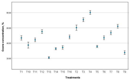
Figure 10.
Error bars to describe the variation in observed data during ozone measurements.
Figure 11 illustrates how oxygen flow rate affects ozone concentration. It demonstrates that the higher the oxygen flow rate, the lower the ozone level. This is because high voltage causes the oxygen molecules to separate and then combine three atoms. If the oxygen conductance is high and the high voltage difference is insufficient, a small amount of ozone is generated. Since ozone is unstable in the presence of the oxygen remaining from the fusion process, the ozone returns to oxygen. To extract ozone at high voltage, a very high potential difference must be used to allow the atoms to combine. However, by increasing the high voltage, the distance between the cathode and the anode must be increased so that there is no high spark as a result of the high voltage difference. Since oxygen helps in combustion, the amount of oxygen present will be burned. In this study, the distance between the cathode and the anode was 1 cm.
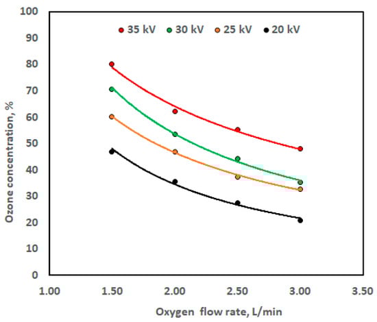
Figure 11.
Ozone concentration against oxygen flow rate at different high voltage levels.
The power function (Equation (1)) was used to designate the relationship between high voltage level and ozone concentration at different levels of oxygen flow rate. The relation represented by Equation (1) was observed previously by Marxuly et al. [40] and Shrestha et al. [41].
where Y is ozone concentration (%), X is oxygen flow rate (L/min), and β0 and β1 are regression constants.
Y = β0Xβ1
From Figure 11, initially, within the oxygen flow rate range of 1.5 to 2.0 L/min, the ozone concentration was fairly high in the range of 62.15% to 80.20%, when the high voltage level was 35 kV. However, when the oxygen flow rate exceeds 2.5 to 3.0 L/min, the ozone concentration decreases from 55.12% to 48.11%. Meanwhile, when the high voltage level decreases to 30 kV and within the range of oxygen flow rate of 1.5 to 2.0 L/min, the ozone concentration decreases from 70.74% to 53.56%; however, when the oxygen flow rate exceeds 2.5 to 3.0 L/min, at the same high voltage level, the reduction in the ozone concentration reaches 44.25 to 35.30%. Moreover, when the high voltage level decreases to 25 kV and within the oxygen flow rate range of 1.5 to 2.0 L/min, the ozone concentration decreases from 60.29% to 46.96%; however, when the oxygen flow rate increases from 2.5 to 3.0 L/min at the same high voltage level, the decrease in the ozone concentration reaches 37.37 to 32.64%. Furthermore, when the high voltage level decreases to 20 kV and within the oxygen flow rate range of 1.5 to 2.0 L/min, the ozone concentration declines from 46.82 to 35.59%; however, when the oxygen flow rate rises from 2.5 to 3.0 L/min at the same high voltage level, a drop in the ozone concentration occurs, going from 27.50 to 20.91%. The ozone concentration during the generation process is negatively affected by an increase in oxygen flow rate, emphasizing the need for an ideal oxygen flow rate to ensure operational ozone production. However, according to Marxuly et al. [40], a similar association was seen, with ozone generation falling between 85 and 120 mg/L with 95% consistency, even when exposed to different high voltage levels (5–25 kV), humidity levels (30–70%), and oxygen flow rates (2–10 L/min). They demonstrated that the concentration drops by 30–50% above 6 L/min. They asserted that initially, the concentration remains high (95–100%) within the range of 2–4 L/min.
Numerous formulas may contain the nonlinear functions associated with the variables X and Y [42]. With the identified dependent variable Y, we took into consideration the most straightforward form of the current data. Microsoft Excel was used as a tool for applying the power function via Windows 10 and Microsoft 365 (2020) on a PC [43]. The experimental data were entered manually into an Excel sheet operating the graphical curves of the data presented in Figure 11 employed trendline option, since, it provided a high R2 compared to other function. Table 2 shows the regression constant values from the power function together with the coefficient of determination (R2). Figure 11 shows also that raising the high voltage level from 20 kV to 35 kV affected on the graph slope. However, the sensitivity of the ozone sensor may vary depending on the oxygen flow rate [44]. Table 2 shows that the β1 value in Equation (1) was (−1.15%/L/min) at the low high voltage level of 20 kV, and the β1 value in Equation (1) was (−0.723%/L/min) at the high voltage level of 35 kV (Table 2).
Table 2.
The values of regression constants (β0 and β1) with the coefficient of determination (R2) for the power function form, (Equation (1)).
Likewise, Figure 12 illustrates how high voltage affects ozone concentration at different oxygen flow rates. At all oxygen flow rates, the graph in Figure 12 illustrates how the ozone concentration rises with the high voltage levels. For example, at oxygen flow rate of 1.5 L/min, the concentration increases significantly from 46.82% to 60.29% when the high voltage level increases from 20 kV to 25 kV, and from 70.74% to 80.20% when the high voltage level increases from 30 kV to 35 kV. This indicates that specific high voltage levels are required to initiate the ozone formation process. It is clear that when the applied high voltage rises, so does the ozone concentration. This is because an increase in high voltage raises the electrical energy density, or the amount of energy that is passed to the electrons, which raises the likelihood that the air in the chamber will collide. Nevertheless, energy supply might not always be enough to recombine ions, radicals, etc. [41].
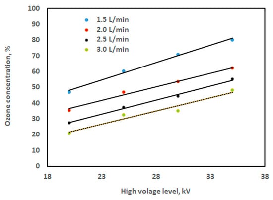
Figure 12.
Ozone concentration against the high voltage level at different oxygen flow rates.
It is found that the high voltage level and ozone concentration have a linear connection, but only within a specific range; however, the high voltage range was 20, 25, 30, and 35 kV, and the flow rate range was 1.5, 2.0, 2.5, and 3.0 L/min. Simple linear regression can be used to describe the data in Figure 12 as follows:
where Y is ozone concentration (%), X is the voltage level (kV), and λ0 and λ1 are regression constants.
Y = λ0 + λ1 × X
Table 3 shows the regression constant values for Equation (2), along with the coefficient of determination (R2). According to a prior study [41], the concentration of ozone increases significantly as the high voltage increases. Three distinct electrode lengths—15 cm, 23 cm, and 31 cm—were used, and the gas flow rate was adjusted between 0.25 and 4 L/min. At an oxygen flow rate of 0.25 L/min and an applied high voltage of 10 kV, a maximum ozone concentration of 3700 ppmv was achieved. Furthermore, according to Yulianto et al. [30], ozone concentration rises with the high voltage. It was discovered that, for a fixed applied high voltage, the ozone concentration falls with increasing flow rate and rises with increasing applied high voltage.
Table 3.
The values of regression constants with the coefficient of determination (R2) for the simple regression function form, (Equation (2)).
Multiple linear regression is used to create a numerical model that explains how the configuration factors of the high voltage level (X1), oxygen flow rate (X2) that affect ozone concentration (Y). Equation (3) is the form of the multiple linear regression model, which is based on several independent variables X to predict a dependent variable Y [45], and the term ε in Equation (3) is the error:
Y = α0 + α1 × X1 + α2 × X2 + … + αp × Xp + ε
To obtain the corresponding regression coefficients (α1 and α2) and constant term (α0), the ozone concentration values and the independent variables (high voltage level (X1, kV) and oxygen flow rate (X2, L/min)) were substituted into Equation (3) in this study. Ultimately, the multiple linear regression model was obtained. Prior to the model’s creation, 80% (12 data points), based on the average values of the samples, were chosen at random to serve as the training set for the quantitative analysis model, and the remaining 20% (4 data points), based on the average values, served as the test set to confirm the constructed model’s capacity for prediction. Regression coefficients for ozone concentration prediction are displayed in Table 4. For the practical selection of an appropriate set of operating conditions in an ozone generator, the obtained equation offers essential information. Equation (4), the multiple linear regression model that was produced to estimate ozone concentration (OC, %), looks like this:
OC (%) = 35.3329 + 1.7168 × X1 − 16.2943 × X2 (Training R2 = 0.973)
Table 4.
Regression coefficients predicting ozone concentration. Standard multiple linear regression analysis (Equation (4)).
According to Jierula et al. [46], the coefficient of determination (R2) and the root mean square error of prediction (RMSE) were the two main statistical metrics used to assess the effectiveness of the developed model. These metrics assess how well the model predicts the data matches the real data. R2 is a number between 0 and 1, with one denoting perfect prediction and 0 denoting no connection. The regression line is better fitted when the R2 value is larger. The RMSE measures the average amount of the error between the expected and actual values. According to Sammen et al. [47] and Tsae et al. [48], RMSE can be calculated as follows:
where N is the number of data points (12 points for training phase and 4 points in testing phase), Pq is the observed value, and is the prediction value. Furthermore, Figure 13 illustrates the correlation between the actual and predicted ozone concentration values using the training dataset, and Figure 14 demonstrates the correlation between the actual and predicted ozone concentration values using the testing dataset.
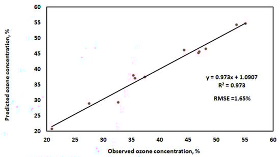
Figure 13.
The relationship between the predicted ozone concentration values and the real ones using the training dataset.
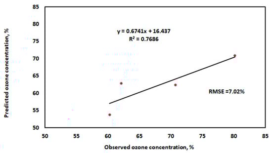
Figure 14.
The relationship between the predicted ozone concentration values and the real ones using the testing dataset.
In Figure 13 and Figure 14, the forecasting accuracy and model performance are compared using RMSE and R2 as evaluation criteria. With the highest R2 value and the lowest error values utilizing training and testing datasets, the results show that the well-established MLR model performed the best. The independent factors in this study account for 97.3% of the variation in the ozone concentration. The Adjusted R Square value for this study is 0.9669. This indicates that the regression line fits 96.69% of the points. Moreover, the accuracy of our multiple regression analysis is indicated by the standard error (1.909%). The statistically significant association between the independent and dependent variables is indicated by the p-value in Table 3. Here, the p-value is less than 0.05. Thus, according to the variables under investigation, the ozone concentration is statistically significant [49].
Drawing from our research, we can highlight the educational value and cost-effective benefits of employing an ozone-generating device, like the presented in this study, which can be used to generate ozone for a variety of purposes. By prolonging shelf life, maintaining sensory qualities, and significantly lowering microbial contamination in agriculture, ozone provides a number of benefits [21]. Ozone generator is approved for generating ozone by low-cost and can be used in educational purposes, although serious safety measures are required to reduce health hazards. Since ozone is a poisonous gas at ground level, its usage in a laboratory requires careful handling and adequate ventilation [50].
4. Conclusions
The development of a low-cost ozone (O3) generator for agricultural and food applications research and education was the focus of this work. The ozone generator uses a cylindrical-shaped chamber as an ozone reactor and is based on corona discharge technology. With the aid of the Arduino platform, the MQ-131 ozone sensor is used to demonstrate and measure the ozone concentration generation rate. The study experiments investigated high voltage levels and various oxygen flow rates. It was discovered that as the applied high voltage increases, so does the concentration of ozone generate. With rising oxygen flow rates at a specific applied high voltage, the ozone concentration increases. Ultimately, the experimental data were used to create a multiple linear regression model for predicting ozone concentration. The model displayed a higher R2 of 0.973 and root mean square error (RMSE) of 1.65% when using the training dataset, and 0.7686 and 7.02%, respectively, when using the testing dataset. Thus, creating a multiple linear regression model can facilitate the early acquisition of data, enhancing or initiating methods for optimizing variables that affect ozone concentration using the device produced. The ozone generator is recommended for low-cost ozone generation and can be used in educational purposes, although serious safety measures are required to reduce health hazards. Since ozone is a poisonous gas at ground level, its usage in a laboratory requires careful handling and adequate ventilation.
Author Contributions
Conceptualization, S.G.H., A.M.A. and M.E.Y.; Methodology, S.G.H., A.M.A. and M.E.Y.; Software, S.M.A.-S., S.S.A., W.A.A. and S.A.M.; Formal analysis, S.G.H., S.A.M., A.M.A. and M.E.Y.; Investigation, S.G.H.; Resources, S.M.A.-S., S.G.H. and S.A.M.; Data curation, A.M.A. and M.E.Y.; Writing—original draft, S.M.A.-S., S.G.H., S.S.A., W.A.A., S.A.M., S.A.A.-H., S.A.-G., S.G.M., A.M.A. and M.E.Y.; Writing—review and editing, S.M.A.-S., S.G.H., S.S.A., W.A.A., S.A.A.-H., S.A.-G., S.G.M., A.M.A. and M.E.Y.; Supervision, S.A.-G.; Funding acquisition, S.A.M. All authors have read and agreed to the published version of the manuscript.
Funding
This research was funded by Ongoing Research Funding Program, (ORF-2025-1217), King Saud University, Riyadh, Saudi Arabia.
Data Availability Statement
The original contributions presented in this study are included in the article. Further inquiries can be directed to the corresponding authors.
Acknowledgments
The authors would like to extend their sincere appreciation to the Ongoing Research Funding Program, (ORF-2025-1217), King Saud University, Riyadh, Saudi Arabia.
Conflicts of Interest
The authors declare no conflicts of interest.
References
- Iksan, M.Z. The Ozone Generator Design for Carrageenan Sterilization Based on Arduino; EasyChair: Stockport, UK, 2021. [Google Scholar]
- Wang, Y.; Qiao, X.J.; Wang, Z.B. Application of ozone treatment in agriculture and food industry. A review. INMATEH-Agric. Eng. 2022, 68, 861–872. [Google Scholar] [CrossRef]
- Vijayan, T.; Patil, J.G. High concentration ozone generation in the laboratory for various applications. Int. J. Sci. Technol. Educ. Res. 2010, 1, 132–142. Available online: https://academicjournals.org/article/article1379500511_Vijayan%20and%20Patil.pdf (accessed on 5 November 2025).
- Guzel-Seydim, Z.B.; Greene, A.K.; Seydim, A. Use of ozone in the food industry. LWT-Food Sci. Technol. 2004, 37, 453–460. [Google Scholar] [CrossRef]
- Brodowska, A.J.; Nowak, A.; Smigielski, K. Ozone in the food industry: Principles of ozone treatment, mechanisms of action, and applications: An overview. Crit. Rev. Food Sci. Nutr. 2018, 58, 2176–2201. [Google Scholar] [CrossRef]
- Liao, R.J.; Yang, L.J.; Li, J.; Grzybowski, S. Aging Condition Assessment of Transformer Oil-Paper Insulation Model Based on Partial Discharge Analysis. IEEE Trans. Dielectr. Electr. Insul. 2011, 18, 303–311. [Google Scholar] [CrossRef]
- Balakrishnan, P.A.; Arunagiri, A.; Rao, P.G. Ozone generation by silent electric discharge and its application in tertiary treatment of tannery effluent. J. Electrost. 2002, 56, 77–86. [Google Scholar] [CrossRef]
- Singh, R.; Narsaiah, K.; Tushir, S. Design and Development of Low Cost Portable Ozone based Fruits and Vegetable Washer-Cum-Purifier. Int. J. Res. Publ. Rev. 2022, 3, 1565–1570. Available online: https://ijrpr.com/uploads/V3ISSUE3/IJRPR3105.pdf (accessed on 5 November 2025).
- El-Mashede, M.B.; Zaky, M.M.; Saleh, A.A.; EL-Hanash, M. Designing of Single Switching DBD Ozone Generator. MEJ-Mansoura Eng. J. 2021, 46, 20–26. [Google Scholar] [CrossRef]
- de Carvalho Costa, L.R.; Toffoli de Oliveira, J.; Amaral Féris, L. Optimization of a Compact Corona Discharge Ozone Generator for Emergency Water Treatment in Brazil. Water 2025, 17, 2430. [Google Scholar] [CrossRef]
- Ghulam, S.T.; Abushammala, H. Challenges and Opportunities in the Management of Electronic Waste and Its Impact on Human Health and Environment. Sustainability 2023, 15, 1837. [Google Scholar] [CrossRef]
- Gäbel, P.; Koller, C.; Hertig, E. Development of Air Quality Boxes Based on Low-Cost Sensor Technology for Ambient Air Quality Monitoring. Sensors 2022, 22, 3830. [Google Scholar] [CrossRef]
- Perry, J.J.; Yousef, A.E. Decontamination of raw foods using ozone-based sanitization techniques. Annu. Rev. Food Sci. Technol. 2011, 2, 281–298. [Google Scholar] [CrossRef]
- Tanriverdi, I.M. What Are the Ozone Generation Methods? Ozon Environmental Solutions 2023. Available online: https://www.ozcon.co.uk/what-are-the-ozone-generation-methods/ (accessed on 1 October 2025).
- Deng, L.Z.; Mujumdar, A.S.; Pan, Z.; Vidyarthi, S.K.; Xu, J.; Zielinska, M.; Xiao, H.W. Emerging chemical and physical disinfection technologies of fruits and vegetables: A comprehensive review. Crit. Rev. Food Sci. Nutr. 2020, 60, 2481–2508. [Google Scholar] [CrossRef]
- Horvitz, S.; Cantalejo, M.J. Application of ozone for the postharvest treatment of fruits and vegetables. Crit. Rev. Food Sci. Nutr. 2014, 54, 312–339. [Google Scholar] [CrossRef] [PubMed]
- Goyal, H. Design and development of an ozone generator for air purification applications. Int. Res. J. Mod. Eng. Technol. Sci. 2025, 7, 4094–4095. Available online: https://www.irjmets.com/upload_newfiles/irjmets70600171230/paper_file/irjmets70600171230.pdf (accessed on 5 November 2025).
- Fahrudin, A.E.; Nasrulloh, A.V.; Sari, N. Development of ozone sterilization system based microcontroller for E. Coli bacteria sterilization. J. Phys. Conf. Ser. 2017, 853, 012007. [Google Scholar] [CrossRef]
- Nehari, L.; Brahami, M.; Bousmaha, I.S.; Labair, H.; Boudjella, F.Z.; Tilmatine, A. Adaptation of a photovoltaic powered ozone generation system for food storage. Carpath. J. Food Sci. Technol. 2019, 11, 64–71. Available online: https://chimie-biologie.ubm.ro/carpathian_journal/Papers_11(4)/CJFST11(4)2019_5.pdf (accessed on 5 November 2025).
- Sarron, E.; Gadonna-Widehem, P.; Aussenac, T. Ozone Treatments for Preserving Fresh Vegetables Quality: A Critical Review. Foods 2021, 10, 605. [Google Scholar] [CrossRef] [PubMed]
- Zhang, K.; Liu, J.; Lv, H.; Zeng, X.; Ling, Z.; Ding, L.; Jin, C. Advances in Ozone Technology for Environmental, Energy, Food and Medical Applications. Processes 2025, 13, 1126. [Google Scholar] [CrossRef]
- Singh, A.N.; Nickhil, C.; Monika Devi, L.; Deka, S.C. Ozone Technology in Agriculture: A Sustainable Approach for Preserving Fruits, Vegetables, and Grains. Ozone Sci. Eng. 2025, 47, 504–534. [Google Scholar] [CrossRef]
- Ozone Gas Sensor, Model: MQ131 Low Concentration, Manual. Available online: https://cdn.sparkfun.com/assets/9/9/6/e/4/mq131-datasheet-low.pdf (accessed on 5 November 2025).
- Caselles Nuñez, J.G.; Contreras Negrette, O.A.; de Jesús Beleño Sáenz, K.; Díaz Sáenz, C.G. Design and Implementation of an Indoor and Outdoor Air Quality Measurement Device for the Detection and Monitoring of Gases with Hazardous Health Effects. Eng. Proc. 2025, 83, 13. [Google Scholar] [CrossRef]
- Yusuf, M.M.; Anwar, M.; Septian, I.R.; Ibrahim, M.H.; Saraswati, T.E. Monitoring and Energy Analysis of Plasma Discharge in Ozone Generator. J. Phys. Conf. Ser. 2022, 2190, 012046. [Google Scholar] [CrossRef]
- Abuzairi, T.; Sumantri, N.I.; Putri, N.A.; Andarini, M.V.; Lampung, E.J.; Sitinjak, D. Development of the Sterilization Box for Medical Equipment with an Ozone Gas Leak Sensor Feature. Int. J. Technol. 2022, 13, 1672–1680. [Google Scholar] [CrossRef]
- Shen, M.; Bennett, N.; Ding, Y.; Scott, K. A concise model for evaluating water electrolysis. Int. J. Hydrog. Energy 2011, 36, 14335–14341. [Google Scholar] [CrossRef]
- Koundi, M.; El Fadil, H. Mathematical modeling of PEM electrolyzer and design of a voltage controller by the SMPWM approach. In Proceedings of the 2019 International Conference on Power Generation Systems and Renewable Energy Technologies (PGSRET), Istanbul, Turkey, 26–27 August 2019; pp. 1–6. [Google Scholar] [CrossRef]
- Tomashevskyi, R.; Kulichenko, V.; Mahonin, N. System for Flow Rate Regulation with Pulse-Width Modulation. In 2014 IEEE 34th International Scientific Conference on Electronics and Nanotechnology (ELNANO); IEEE: New York, NY, USA, 2014; pp. 277–280. [Google Scholar] [CrossRef][Green Version]
- Yulianto, E.; Aryadi, R.; Zahar, I.; Sasmita, E.; Restiwijaya, M.; Kinandana, A.W.; Arianto, F.; Nur, M. Effect of duty cycle on ozone production using DBDP cylindrical reactor. J. Phys. Conf. Ser. 2019, 1217, 012011. [Google Scholar] [CrossRef]
- Waskito, A.; Firmansyah, R.D.; Syamsi, D.; Baskoro, C.H.A.H.B.; Lisdiana, A.; Wahab, H.I. Optimization of ozone chamber using pulse width modulation for sterilization and preservation on fruits and vegetable. J. Mechatron. Electr. Power Veh. Technol. 2020, 11, 111–116. [Google Scholar] [CrossRef]
- Shen, C.-L.; Liang, T.-C. Design and Implementation of a High-Voltage Generator with Output Voltage Control for Vehicle ER Shock-Absorber Applications. Math. Probl. Eng. 2013, 2013, 324590, 6 p. [Google Scholar] [CrossRef]
- Kaur, K.; Kaur, P.; Kumar, S.; Zalpouri, R.; Singh, M. Ozonation as a Potential Approach for Pesticide and Microbial Detoxification of Food Grains with a Focus on Nutritional and Functional Quality. Food Rev. Int. 2023, 39, 6129–6161. [Google Scholar] [CrossRef]
- Sitoe, E.D.P.E.; Pacheco, F.C.; Chilala, F.D. Advances in ozone technology for preservation of grains and end products: Application techniques, control of microbial contaminants, mitigation of mycotoxins, impact on quality, and regulatory approvals. Compr. Rev. Food Sci. Food Saf. 2025, 24, e70173. [Google Scholar] [CrossRef]
- Dubey, P.; Singh, A.; Yousuf, O. Ozonation: An Evolving Disinfectant Technology for the Food Industry. Food Bioprocess Technol. 2022, 15, 2102–2113. [Google Scholar] [CrossRef]
- Septian, I.R.; Anwar, M.; Yusuf, M.M.; Kusuma, R.R.; Saraswati, T.E.; Sulistyo, M.E.; Adinata, F.S. Design and analysis of ozone monitoring system produced by plasma corona discharge for disinfectant. AIP Conf. Proc. 2023, 2674, 030055. [Google Scholar] [CrossRef]
- Alonso Álvarez, J.M.; García García, J.; Calleja Rodríguez, A.J.; Ribas Bueno, J.; Cardesín Miranda, J. Analysis, design, and experimentation of a high-voltage power supply for ozone generation based on current-fed parallel-resonant push-pull inverter. IEEE Trans. Ind. Appl. 2005, 41, 1364–1372. [Google Scholar] [CrossRef]
- IBM Corp. IBM SPSS Statistics for Windows, version 27.0. Computer software; IBM Corp: Armonk, NY, USA, 2020.
- El Gharbi, M.; Abounasr, J.; Fernández-García, R.; Gil, I. Study of Wash-Induced Performance Variability in Embroidered Antenna Sensors for Physiological Monitoring. Electronics 2025, 14, 2084. [Google Scholar] [CrossRef]
- Marxuly, S.; Abdykadyrov, A.; Yussupova, G.; Mailykhanova, B.; Mustafoyeva, D. Development of nonlinear multi-parameter control models for optimizing ozone generation processes. Int. J. Innov. Res. Sci. Stud. 2025, 8, 969–982. [Google Scholar] [CrossRef]
- Shrestha, R.; Joshi, U.M.; Subedi, D.P. Experimental Study of Ozone Generation by Atmospheric Pressure Dielectric Barrier Discharge. Int. J. Recent Res. Rev. 2015, VIII, 24–29. Available online: https://www.ijrrr.com/papers8-4/paper4-Experimental%20Study%20of%20Ozone%20Generation%20by%20Atmospheric%20Pressure%20Dielectric%20Barrier%20Discharge.pdf (accessed on 5 November 2025).
- Warsza, Z.L.; Puchalski, J.; Więcek, T. Novel Method of Fitting a Nonlinear Function to Data of Measurement Based on Linearization by Change Variables, Examples and Uncertainty. Metrology 2024, 4, 718–735. [Google Scholar] [CrossRef]
- Suwannahong, K.; Wongcharee, S.; Kreetachart, T.; Sirilamduan, C.; Rioyo, J.; Wongphat, A. Evaluation of the Microsoft Excel Solver Spreadsheet-Based Program for Nonlinear Expressions of Adsorption Isotherm Models onto Magnetic Nanosorbent. Appl. Sci. 2021, 11, 7432. [Google Scholar] [CrossRef]
- Pang, X.; Shaw, M.D.; Lewis, A.C.; Carpenter, L.J.; Batchellier, T. Electrochemical ozone sensors: A miniaturised alternative for ozone measurements in laboratory experiments and air-quality monitoring. Sens. Actuators B Chem. 2017, 240, 829–837. [Google Scholar] [CrossRef]
- Dorta-González, P. A Multiple Linear Regression Analysis to Measure the Journal Contribution to the Social Attention of Research. Axioms 2023, 12, 337. [Google Scholar] [CrossRef]
- Jierula, A.; Wang, S.; OH, T.-M.; Wang, P. Study on Accuracy Metrics for Evaluating the Predictions of Damage Locations in Deep Piles Using Artificial Neural Networks with Acoustic Emission Data. Appl. Sci. 2021, 11, 2314. [Google Scholar] [CrossRef]
- Sammen, S.S.; Kisi, O.; Ehteram, M.; El-Shafie, A.; Al-Ansari, N.; Ghorbani, M.A.; Bhat, S.A.; Ahmed, A.N.; Shahid, S. Rainfall modeling using two different neural networks improved by metaheuristic algorithms. Environ. Sci. Eur. 2023, 35, 112. [Google Scholar] [CrossRef]
- Tsae, N.B.; Adachi, T.; Kawamura, Y. Application of Artificial Neural Network for the Prediction of Copper Ore Grade. Minerals 2023, 13, 658. [Google Scholar] [CrossRef]
- Abdul Kader, M. How to Interpret Multiple Regression Results in Excel. Excel Demy, 2024. Available online: https://www.exceldemy.com/interpret-multiple-regression-results-in-excel/ (accessed on 1 October 2025).
- High Voltage DIY Ozone Generator for Disinfection. Available online: https://hackaday.io/project/202959-high-voltage-diy-ozone-generator-for-disinfection#:~:text=Description,electrode%20and%20an%20air%20tube (accessed on 31 October 2025).
Disclaimer/Publisher’s Note: The statements, opinions and data contained in all publications are solely those of the individual author(s) and contributor(s) and not of MDPI and/or the editor(s). MDPI and/or the editor(s) disclaim responsibility for any injury to people or property resulting from any ideas, methods, instructions or products referred to in the content. |
© 2025 by the authors. Licensee MDPI, Basel, Switzerland. This article is an open access article distributed under the terms and conditions of the Creative Commons Attribution (CC BY) license (https://creativecommons.org/licenses/by/4.0/).