Abstract
The flow and solidification inside the mould are crucial to the quality of the casting billet during continuous casting. In this work, a three-dimensional coupled model of flow and solidification was established, and the flow field and temperature distribution characteristics of molten steel were deeply explored. The results indicated that the molten steel streams out of the SEN at a defined degree and enters the mould in the form of an impact stream, and then impacts the narrow surface. The eddy core position in the upper recirculation region of the flow field is (0.565 m, −0.179 m), and eddy core position in the lower recirculation region is (0.524 m, −0.455 m). Within the range of 100–400 mm from the liquid surface, the main stream and upper ring flow of molten steel have a significant impact on the solidification of the casting billet, and the distribution and longitudinal variation in the liquid phase ratio at different height sections are very obvious. At the exit of the mould, the average thickness of the inner arc and outer arc shells is 15.2 mm and 14.5 mm, respectively. The model can provide guidance for enhancing and optimizing the quality of continuous casting billets.
1. Introduction
In the production of steel, continuous casting is the main production method and a key link affecting the quality of steel. In a continuous casting process, the molten steel flows into the mould from the ladle through the nozzle, forming an initial solidified shell under the action of cooling water. In the mould, the high-temperature molten steel rapidly solidifies upon hitting the mould wall, forming a thin shell, while the central area remains liquid. After reaching the secondary cooling zone, the cast billet can fully solidify. The protective slag inside the mould lubricates and improves heat transfer of the casting billet. As the mould vibrates, the solidified shell continues to grow and move to the secondary cooling zone of continuous casting, until the entire cross-section of the casting billet is completely solidified. The mechanism of molten steel flow and the process of solidification in the mould are very important and affect the quality of the casting billet. Due to the high temperature inside the continuous casting mould, which is not conducive to testing, the current research on the flow and solidification of molten steel in the mould is still not very deep. Solidification and flow interact with each other, so it is necessary to conduct a coupled study of solidification and flow in molten steel [1,2,3,4,5,6,7,8].
Several scholars conducted research on the flow and transfer in moulds [9,10,11,12,13,14,15,16,17]. Yang et al. [18] focused on the flow properties of special steel within the tundish. They built a volume subtraction model by using a lot of evaluation methods such as the individual unit method, in which the flow behavior of steel was presented. Patil et al. [19] conducted three-dimensional calculations of isothermal steady-state tundish flow. The results consisted of the residence time distribution analysis and inclusion transport. Huang et al. [20] developed a swirl tundish that achieved a deep clean of molten steel by promoting the aggregation of inclusions. Their method utilized the gravitational potential energy of molten steel to generate vortices and did not need an external energy input. Because of the density difference between inclusions and molten steel, the inclusions would aggregate towards the center of the vortex, resulting in small-sized inclusions aggregating into larger particles, and then it flowed up to the meniscus of the liquid steel by its own buoyancy. Sheng et al. [21] built up the flow patterns within different intermediate package structures and visualized and measured the residence time distribution by using a scaled water model. The CFD algorithm was used to simulate the water flow, thermal conductivity, and residence time distribution curves under the condition of a non-isothermal environment. The movement of the bubble was simulated by assuming the Euler–Lagrange method. Their results indicated that the distinct flow control device has special flow field control functions. Bai et al. [22] numerically studied the influence of the outlet design of swirl-immersed SEN on multiphase flow and thermal conductivity in the mould. The results show that different SEN outlet designs would lead to different flow field shapes and thermal fields in the upper part of the mould. Among them, if the outlet type of SEN design was expanded, it could effectively reduce the horizontal flow speed of the molten steel when it flows out of the water outlet, and further reduce the steel flow speed towards the solidification frontier. Tripathi et al. [23] studied the flow performance in the billet continuous casting mould and analyzed the reasons for bias flow by building a fluid dynamics model. They found that even if the SEN and other flow parameters are completely symmetrical, there will inevitably be a problem of bias flow on one side of the continuous casting machine. Based on their research, it was found that the interaction between jet fluctuations and multiple steel flows near the meniscus region were the main reason for the phenomenon. They further indicated that after a period of time, an unsteady stream would be formed inside the mould, and this flow characteristic was apparently affected by the pulling speed.
While numerous researchers in the field of continuous casting metallurgy have carried out extensive investigations into the flow field dynamics within the continuous casting mould. Specifically, critical questions regarding how flow-induced temperature gradients regulate the growth rate and uniformity of the solidified shell, how solidification shrinkage modifies the flow patterns in the mould, and how turbulent mixing affects the stability of the solid–liquid interface have not been fully addressed by existing studies. Therefore, in this work a three-dimensional nozzle model was presented to reveal the flow and solidification characteristics in the mould. The proposed model is expected to provide practical, data-driven guidance for engineers to enhance process stability and optimize the quality of continuous casting billets—for instance, by aiding in the mitigation of common defects like longitudinal cracks, slag entrapment, and asymmetric shell growth that often arise from unregulated flow–solidification interactions.
2. Model Description
2.1. Model
The calculation object is the slab casting machine of a domestic steel plant. Half of the casting billet is selected as the calculation area, and the solid model and grid division of the casting billet is shown in Figure 1.
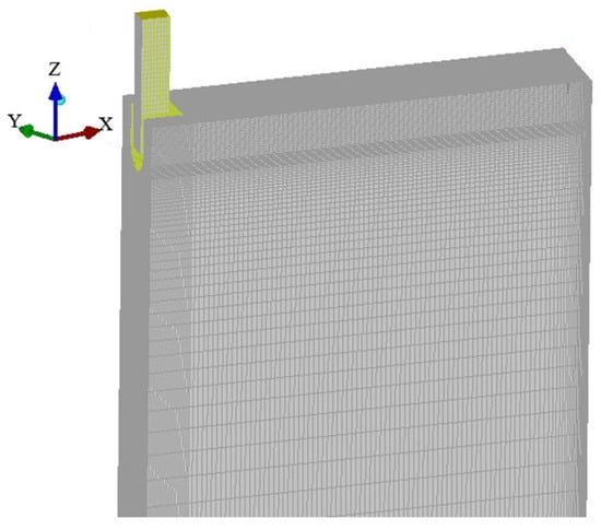
Figure 1.
The solid model and grid division of the casting billet.
2.2. Assumption
Based on Navier–Stokes momentum equation and turbulent flow described by the Reynolds number and k-ε equation, considering the conservation of energy and the influence of steel solidification and paste zone on the flow process, a 3D mathematical model is developed to describe the flow and solidification of steel in the mould. The following assumptions are made:
- (1)
- The steel liquid is a non-compressible Newtonian fluid, where the effect of mould oscillation is ignored.
- (2)
- The non-slip boundary is assumed, where the speed and energy are all zero.
- (3)
- The influence of phase transition is neglected.
- (4)
- The solidification shrinkage of the billet and the density-driven natural convection are ignored. While the molten steel quickly flows into the mould through the water outlet, which flushes the molten steel inside the mould and generates steel convection, the density variation in steel is extremely slight. Consequently, the natural convection induced by this density change and oscillation is much weaker than the forced convection from the steel strike, making it negligible. Additionally, the displacement resulting from casting slab contraction is very small, so its disturbance to the flow can also be disregarded [24].
2.3. Governing Equation
- (1)
- Mass-conservation equation:
- (2)
- Momentum conservation equation:
- (3)
- Energy equation:
- (4)
- Turbulence control equation:
The standard k − ε dual equation model is as follows:
where k is the turbulent pulsation kinetic energy; ε is the dissipation rate of turbulent pulsation kinetic energy; C1, C2, σk, and σε are constants; Gk represents the turbulent flow energy generation term; and Sk and Sε are the source terms added to the equation.
- (5)
- Solid phase:
The solidification state is defined by the solid fraction fs of the molten steel and the equivalent specific heat process applied to manage the latent heat of solidification.
where fs is the solid phase volume fraction, TL and TS are the liquidus temperature and solidus temperature of the molten steel; and T is the temperature of the molten steel.
2.4. Boundary Conditions
The model employs the following boundary conditions:
- (1)
- The condition of the inlet is set as the velocity inlet.
- (2)
- The condition of the outlet is set as the velocity outlet, while the outlet velocity equals the drawing velocity.
- (3)
- The liquid surface of the mould is set as a free surface, with no shear force.
- (4)
- The non-slip solid walls are applied for both the mould wall and the SEZ wall, while the standard wall function is applied for the flow distribution around the edge. The temperature is set as adiabatic of the nozzle wall.
The time step is 5 ms, and the residual convergence rule is less than 10−6. The grid sensitivity is shown in Table 1. In this calculation, when the number of grid is more than 450,000, the average shell thickness is very small and it could be considered that changes in the mesh have no effect on the computational results.

Table 1.
Grid sensitivity calculation.
The main factors are listed in Table 2.
Table 2.
The calculated parameters.
3. Results and Discussion
3.1. Vortex Center Position
Figure 2 is the flow contours of molten steel in the mould, the vortex center position in the upper recirculation zone of the flow field is (0.565 m, −0.179 m), while it is located at (0.524 m, −0.455 m) in the lower recirculation zone. In the figure, the molten steel flows out of the submerged nozzle at a certain degree and enters the mould in the form of an impact stream, and then impacts the narrow surface. As the molten steel reaches the narrow side, the velocity of the molten steel continues to decrease, the momentum also decreases, and the main stream stock continues to expand. After reaching the narrow surface and forming a certain impact on it, some of the steel liquid flows towards the meniscus while the other part moves towards the exit of the mould, forming two major streams: an upward stream and a downward stream. The upward stream flows along the solidified billet shell, forming an upward reflux zone, which directly affects the disturbance of the loose liquid surface, the floating of slag, and any inclusions. During the continuous casting process, molten steel continuously flows into the mould from the tundish. To prevent the oxidation of molten steel, mould flux is added to its surface, which floats on the surface. After the molten steel flows out of the nozzle, it forms a recirculation zone, and the upward recirculation zone will affect the surface of the molten steel and the mould flux. The downward flow stream moves downwards along the narrow side of the billet shell, forming a large scope of downward reflux zones. The computational results of this study are consistent with the computational results of Takatani et al. and Li et al. [25,26], and at the same time, they show good agreement with the experimental results of Shamsi et al. and Lu et al. [27,28].
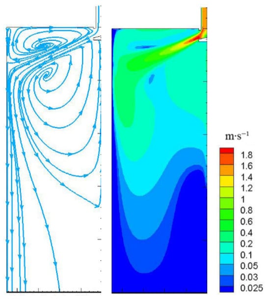
Figure 2.
The flow contours of molten steel in the mould.
3.2. Liquid Phase Ratio of Cross-Section
Figure 3 shows the distribution of liquid phase fraction of billet at different heights inside the mould. It can be seen that the corner shell grows faster at the same height due to the two-dimensional cooling effect, and the thickness of the shell at the lower mouth of the mould is also the largest. Due to the asymmetric heat flux density between the inner and outer arcs, especially in the high heat flux zone in the upper part of the mould, the contour lines of the liquid phase ratio are slightly inclined. The lower heat flux of the outer arc causes the growth of the shell to be relatively slow, and the contour lines of the liquid phase ratio lean towards the outer arc side. It can be seen that within the range of 100–400 mm from the liquid surface, the main stream and upper ring flow of molten steel have a significant impact on the solidification of the casting billet, and the distribution and longitudinal variation in the liquid phase ratio at different height sections are very obvious. Downwards along the casting direction, with the increase in air gap and shell thickness, the heat flux rapidly decreases. Under the effect of large-scale reverse streams of liquidus steel in the lower circulation area, the distinction of heat transfer between the inner and outer arcs is reduced, and the contour lines in the middle and lower parts gradually tend towards center symmetry [22,23]. The steel liquid flushing slightly reduces the thickness of the solidified slab in the middle of a narrow side 400 mm below the liquid level, but this effect is no longer significant below 600 mm, and the narrow surface shell tends to grow uniformly again.
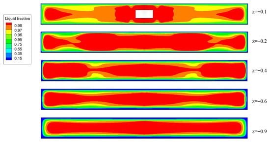
Figure 3.
Liquid fraction at different heights.
3.3. Liquid Phase Ratio of Longitudinal Section
The distribution of liquid phase ratios in different longitudinal sections of the molten steel inside the mould is shown in Figure 4. The liquid–solid fields and distributions of the molten steel in the casting billet are corresponded to Figure 3. The liquid molten steel gradually solidifies into a solid state under the cooling influence exerted by the mould along the casting billet pulling speed direction, and the solidified billet shell gradually thickens with the continuous downward movement of the casting billet. The non-uniformity of solidification is not well reflected in the longitudinal section of the liquid phase ratio distribution map, and the liquid–solid phases are basically symmetrically distributed.
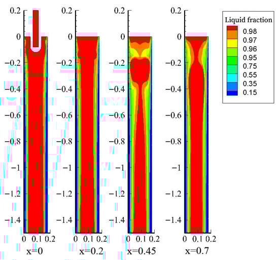
Figure 4.
Liquid fraction at different slab longitudinal sections.
3.4. Thickness of Solidification Shell
Figure 5 shows the thickness distribution of the solidified layer of the cast billet at different positions inside the mould. Overall, due to the significant unevenness of the reverse calculated heat flux on the same wide surface, the heat flux on the two wide surfaces is not symmetrical, resulting in an uneven distribution of the calculated shell thickness. At the exit of the mould, the average thickness of the inner arc and outer arc shells is 15.2 mm and 14.5 mm, respectively, with a difference of 4.6%. The results of shell thickness are consistent with the research findings reported by Cho et al. [29] and Zhu et al. [30]. The difference in the average heat flux calculated from the two wide surfaces is 5.4%, and the overall trend of heat flux and shell thickness is consistent. In the high heat flux zone from the meniscus to 200 mm below it, the growth rate of the shell is significantly faster, and the average thickness of the shell reaches 6 mm at the 200 mm position. Below the high heat flux zone, the growth of the shell gradually slows down with the decrease in heat flux. The appearance of air gaps in the area below 400 mm from the liquid level of the mould significantly reduces the heat flow, and further slows down the growth rate of the shell at different positions. At the outlet of the mould, the inner arc center and 1/4 wide surface of the billet shell are relatively uniform, measuring 15.4 mm and 15.0 mm, respectively. The uniformity of the outer arc shell is poor, with a thickness of 15.1 mm and 13.9 mm at the center and 1/4 wide surface positions, respectively. The surface temperature of the shell is high within the range of 1/4 wide surface to 200 mm from the narrow surface, and weak shells with local high temperatures are prone to defects such as longitudinal cracks. Based on the above results, obtaining the non-uniform flow field of molten steel and the solidification state of the billet shell through inverse calculation of heat flux can provide important clues for further research on the generation and online prediction of longitudinal and surface cracks [31].
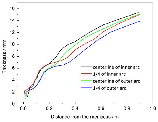
Figure 5.
Thickness of shell at different location of the slab wide side in the mould.
4. Conclusions
- (1)
- The molten steel flows out of the submerged nozzle at a certain angle and enters the mould in the form of an impact stream, and then impacts the narrow surface. The eddy core position in the upper recirculation region of the flow field is (0.565 m, −0.179 m), and eddy core position in the lower recirculation region is (0.524 m, −0.455 m).
- (2)
- Within the range of 100–400 mm from the liquid surface, the main stream and upper ring flow of molten steel have a significant impact on the solidification of the casting billet, and the distribution and longitudinal variation in the liquid phase ratio at different height sections are very obvious.
- (3)
- The steel liquid flushing slightly reduces the thickness of the solidified slab in the middle of a narrow side 400 mm below the liquid level, but this effect is no longer significant below 600 mm, and the narrow surface shell tends to grow uniformly again.
- (4)
- The heat flux on the two wide surfaces is not symmetrical, resulting in an uneven distribution of the calculated shell thickness. At the outlet of the mould, the average thickness of the inner arc and outer arc shells is 15.2 mm and 14.5 mm, respectively, with a difference of 4.6%. At the outlet of the mould, the inner arc center and 1/4 wide surface of the billet shell are relatively uniform, measuring 15.4 mm and 15.0 mm, respectively.
Author Contributions
Data curation, T.L., S.Z., W.L. and F.D.; writing, G.L. All authors have read and agreed to the published version of the manuscript.
Funding
General Project of Natural Science Foundation of Liaoning Province (2025-MS-309) and Basic Scientific Research Project of the Department of Education of Liaoning Province (LJ212513217002).
Data Availability Statement
Data are contained within the article.
Conflicts of Interest
Author Tianyi Li was employed by the Offshore Oil Engineering Co., Ltd. The remaining authors declare that the research was conducted in the absence of any commercial or financial relationships that could be construed as a potential conflict of interest.
References
- Saeedipour, M.; Pirker, S. Analysis of hysteresis in the regime transition of cocurrent liquid-gas flow. Steel Res. Int. 2022, 93, 2100800. [Google Scholar] [CrossRef]
- Chen, W.; Ren, Y.; Zhang, L.F. Large eddy simulation on the two-phase flow in a water model of continuous casting strand with gas injection. Steel Res. Int. 2019, 90, 1800287. [Google Scholar] [CrossRef]
- Glavinic, I.; Galindo, V.; Stefani, F.; Wondrak, T. Contactless inductive flow tomography for real-time control of electromagnetic actuators in metal casting. Sensors 2022, 22, 4155. [Google Scholar] [CrossRef] [PubMed]
- Srinivas, P.S.; Mishra, D.K.; Kulkarni, A.B.; Gupta, R.; Korath, J.M.; Jana, A.K. Investigation of vortex flow patterns at the meniscus in a water caster mould. Can. Metall. Q. 2020, 59, 211–232. [Google Scholar] [CrossRef]
- Zhao, P.; Piao, R.X. Lattice boltzmann method modeling of the evolution of coherent vortices and periodic flow in a continuous casting mold. Metals 2022, 12, 572. [Google Scholar] [CrossRef]
- Zhi, Q.; Niu, J.P.; Tan, X.R.; Pei, R.; Liu, Y.; Chen, Y.Q.; Liu, W.H. Effect of scanning process and heat treatment on microstructure and mechanical property of inconel 718 fabricated by selective laser melting. J. Mater. Eng. Perform. 2024, 32, 9515–9524. [Google Scholar] [CrossRef]
- Wang, S.J.; Xu, P.; Zhou, Y.Z.; Duan, H.M.; Chen, D.F.; Long, M.J. The effect of mold structure and cooling parameters on heat transfer during billet high-speed continuous casting. Materials 2023, 16, 3361. [Google Scholar] [CrossRef]
- Kim, H.S.; Kim, J.J.; Oh, K.S. A simplified model for semi-continuous casting of steel. J. Mater. Eng. Perform. 2023, 32, 4064–4070. [Google Scholar] [CrossRef]
- Li, Y.G.; Chen, W.Q.; Sun, Y.H. Analysis of macrosegregation during slab continuous casting using 3D-longitudinal 2D hybrid model. Ironmak. Steelmak. 2023, 50, 794–808. [Google Scholar] [CrossRef]
- Peng, Z.Q.; Liu, Q.; Guo, D.W.; Zeng, Z.H.; Cao, J.H.; Hou, Z.B. Independent change law of mold heat transfer in continuous casting based on big data mining. Acta Metall. Sin. 2023, 59, 1389–1400. [Google Scholar] [CrossRef]
- Zhu, X.W.; Liu, X.C.; Zhao, L.J.; Li, D.W.; Tian, C.; Wang, K.; Jin, B.G.; Wang, Q. Electromagnetic swirling flow control in nozzle in slab continuous casting. J. Iron Steel Res. Int. 2025, 32, 935–949. [Google Scholar] [CrossRef]
- Liu, X.C.; Zhu, X.W.; Sun, Y.W.; Sun, M.J.; Zhao, L.J.; Liu, X.M.; Wang, Q. Flow field control within slab mold under different casting speeds by electromagnetic swirling flow in nozzle. J. Iron Steel Res. Int. 2025, 32, 3342–3354. [Google Scholar] [CrossRef]
- Zhang, S.Y.; Sun, Y.W.; Liu, Z.Y.; Sun, M.J.; Liu, X.M.; Mu, W.Z.; Liu, T.; Wang, Q. Mechanism of inclusions control influenced by electromagnetic swirling flow in nozzle compared to mold electromagnetic stirring. Mater. Today Commun. 2025, 44, 112003. [Google Scholar] [CrossRef]
- Ren, B.Z.; Zhu, L.L.; Wang, H.D.; Chen, D.F. Numerical simulation of fluid flow and solidification in round bloom continuous casting with alternate final electromagnetic stirring. Metals 2025, 15, 605. [Google Scholar] [CrossRef]
- Lai, Q.R.; Luo, Z.G.; Zhang, Y.J.; Zou, Z.S.; Li, H.F. Numerical simulation of bubble flow in continuous casting mold with bubble swarm correction of drag coefficient. Metals 2025, 15, 952. [Google Scholar] [CrossRef]
- Deng, Y.L.; Deng, N.Z.; Duan, J.T.; Li, Y.B.; Gao, Q.; Ni, W.H.; Peng, J.Q. Influence of processing parameters on flow behaviour of ultra-large-section beam blank continuous casting mould. Materials 2025, 18, 275. [Google Scholar] [CrossRef]
- Liang, B.C.; Han, C.X.; Zhao, T.; Ji, C.; Zhu, M.Y. Research on constitutive modeling of DH460 continuous casting steel with the solidification end reduction process. Materials 2025, 18, 453. [Google Scholar] [CrossRef]
- Yang, B.; Lei, H.; Xu, Y.S.; Liu, K.; Han, P. Numerical investigation of flow characteristics of molten steel in the tundish with channel induction heating. Metals 2022, 11, 1937. [Google Scholar] [CrossRef]
- Patil, S.P.; Viswanathan, N.N. Numerical investigation of single-strand slab casting tundish flow with heat transfer and inclusion transport. Trans. Indian Inst. Met. 2021, 74, 369–379. [Google Scholar] [CrossRef]
- Huang, W.X.; Chang, S.; Zou, Z.S.; Shao, L.; Qu, Y.X.; Li, B.K. Modeling of flow behaviors in a swirling flow tundish for the deep cleaning of molten steel. Steel Res. Int. 2021, 92, 2100012. [Google Scholar] [CrossRef]
- Sheng, D.Y.; Chen, D.F. Comparison of fluid flow and temperature distribution in a single-strand tundish with different flow control devices. Metals 2021, 11, 796. [Google Scholar] [CrossRef]
- Bai, H.T.; Ni, P.Y.; Ersson, M.; Zhang, T.G.; Josson, P.G. Effect of swirling flow tundish submerged entry nozzle outlet design on multiphase flow and heat transfer in mould. Ironmak. Steelmak. 2019, 46, 911–920. [Google Scholar] [CrossRef]
- Tripathi, A.; Ajmani, S.K.; Chandra, S. Numerical investigation of bias flow in a slab caster mould. Can. Metall. Q. 2021, 60, 203–214. [Google Scholar] [CrossRef]
- Mramor, K.; Vertnik, R.; Šarler, B. Development of three-dimensional LES based meshless model of continuous casting of steel. Metals 2022, 12, 1750. [Google Scholar] [CrossRef]
- Takatani, K. Effects of electromagnetic brake and meniscus electromagnetic stirrer on transient molten steel flow at meniscus in a continuous casting mold. ISIJ Int. 2003, 43, 915–922. [Google Scholar] [CrossRef]
- Li, B.K.; Tsukihashi, F. Effects of electromagnetic brake on whirlpool flows in thin slab continuous casting mold. ISIJ Int. 2006, 46, 1833–1838. [Google Scholar] [CrossRef]
- Shamsi, M.R.R.I.; Ajmani, S.K. Three dimensional turbulent fluid flow and heat transfer mathematical model for the analysis of a continuous slab caster. ISIJ Int. 2007, 47, 433–442. [Google Scholar] [CrossRef]
- Lu, B.W.; Yuan, F.L.; Wang, H.L.; Bai, H. Water model experimental study on the behavior of fluid flow in slab caster mold. Res. Iron Steel 2015, 43, 24–27. [Google Scholar]
- Cho, J.; Shibata, H.; Emi, T.; Suzuki, M. Radiative heat transfer through mold flux film during initial solidification in continuous casting of steel. ISIJ Int. 1998, 38, 268–275. [Google Scholar] [CrossRef]
- Cai, Z.Z.; Zhu, M.Y. Simulation of air gap formation in slab continuous casting mould. Ironmak. Steelmak. 2014, 41, 435–446. [Google Scholar] [CrossRef]
- Du, F.M.; Wang, X.D.; Liu, Y.; Li, T.Y.; Yao, M. Analysis of non-uniform mechanical behavior for a continuous casting mold based on heat flux from inverse problem. J. Iron Steel Res. Int. 2016, 23, 83–91. [Google Scholar] [CrossRef]


Disclaimer/Publisher’s Note: The statements, opinions and data contained in all publications are solely those of the individual author(s) and contributor(s) and not of MDPI and/or the editor(s). MDPI and/or the editor(s) disclaim responsibility for any injury to people or property resulting from any ideas, methods, instructions or products referred to in the content. |
© 2025 by the authors. Licensee MDPI, Basel, Switzerland. This article is an open access article distributed under the terms and conditions of the Creative Commons Attribution (CC BY) license (https://creativecommons.org/licenses/by/4.0/).