Abstract
To address the issue of wellbore instability during drilling in fractured formations, this study systematically investigates the influence mechanisms of fracture geometry and strength parameters on wellbore stability by constructing a multi-weak plane strength criterion and a thermo-hydro-chemical coupling model. Based on Jæger’s single weak plane criterion, a multi-weak plane strength criterion considering the synergistic effects of multiple fracture groups is established. By integrating Boit’s effective stress theory, an analytical solution for the stress field around a wellbore in fractured formations has been derived. A method for calculating collapse pressure and predicting instability zones is also proposed, utilizing the Newton–Raphson iterative algorithm. The results demonstrate that fracture systems markedly alter the anisotropic characteristics of wellbore stress. While the collapse pressure contour in intact formations exhibits bilateral symmetry (25.5–30 MPa), in formations with four fractures, the pressure increases to 29–37 MPa and the symmetry is lost. Furthermore, the instability zone in vertical wells evolves from a “crescent-shaped” pattern in homogeneous formations to a “quadrilateral-shaped” expansion. Notably, the instability area in horizontal wells is significantly smaller than in vertical wells. These outcomes offer theoretical guidance for optimizing the drilling fluid density window and well trajectory design in fractured formations.
1. Introduction
With the continuous growth of global energy demand and accelerated development of unconventional oil and gas resources, fractured reservoirs such as shale and tight formations have become major research focuses on petroleum engineering worldwide. The systematic application of anisotropic wellbore stability analysis has demonstrated critical importance in major hydrocarbon basins including the Marcellus Shale in North America, Sichuan Basin in China, and Asmari formations in the Middle East, where complex fracture networks significantly impact drilling operations. In these contexts, wellbore instability has emerged as a paramount technical challenge hindering safe and efficient drilling [1,2,3,4,5]. Global industry statistics reveal that non-productive time caused by wellbore instability accounts for approximately 5–10% of total drilling time worldwide, generating annual economic losses reaching $5–6 billion USD [6,7,8,9,10,11]. This challenge is particularly pronounced in complex well architectures such as shale gas horizontal wells and extended-reach wells, where natural fracture systems coupled with drilling fluid-rock interactions trigger severe wellbore collapse and well narrowing incidents [12,13,14,15,16]. The significant heterogeneity and anisotropy characterizing fractured formations—whose mechanical behavior depends critically on fracture occurrence, density, and fill state—render traditional wellbore stability models, based on homogeneous continuum assumptions, fundamentally inadequate [17,18,19,20]. Consequently, elucidating the mechanistic influence of fracture systems on wellbore stability and establishing scientifically rigorous evaluation methodologies carries substantial theoretical significance and engineering value for optimizing drilling designs and mitigating operational risks in such complex formations.
In the field of wellbore stability research in fractured formations, significant progress has been made by scholars in the world [21,22,23,24,25,26]. Early studies on wellbore stability primarily relied on elastic mechanics, treating fractures as isolated weak planes. Bradley [27] established a foundational analytical elastic model for calculating wellbore stress distributions. Later, Zoback et al. [28] developed a method to assess how wellbore collapse pressure varies with azimuth by considering the orientation of the maximum horizontal stress relative to the well path. However, these early models did not fully account for the anisotropy of fractured rock masses, leading to significant deviations from actual field observations [29,30,31,32]. As rock mechanics testing advanced, research began to focus more on the strength anisotropy of fractured rocks. For example, Fan et al. [33] used scanning electron microscopy and acoustic experiments to show that the elastic modulus of continental shale in the Ordos Basin can vary by up to 2.3 times depending on bedding orientation—demonstrating the dominant influence of bedding planes on mechanical behavior. Theoretically, the Mohr–Coulomb weak plane failure criterion has been widely used to model formations with multiple weak planes [34,35,36,37,38]. Liu et al. [39] introduced a wellbore collapse model incorporating multiple weak planes. By applying the superposition principle, their model successfully captured instability behavior caused by the interaction between fracture orientation and wellbore azimuth.
In recent years, numerical simulation methods have provided new technical means for studying wellbore stability in fractured formations [40,41,42,43,44]. Chen et al. [45] first introduced the discrete element method into the analysis of fractured reservoirs, revealing the degradation of fracture friction angle due to mud infiltration. Subsequently, Al-Ajmi [13] developed a true triaxial wellbore stability model based on the Mogi–Coulomb criterion, which incorporated the often-neglected intermediate principal stress and significantly improved predictive accuracy. In research on dynamic failure mechanisms, Zeng et al. [21] conducted an energy evolution analysis and found that dissipated energy accounts for 60–70% of the total energy during shale unloading, providing a new basis for energy-based wellbore instability criteria. Regarding chemo-mechanical coupling, Deng et al. [37] established a seepage-stress model showing how hydration-induced swelling reshapes the near-wellbore stress field, while Nwonodi et al. [14] further integrated membrane efficiency to advance time-dependent stability analysis. Their results indicated that instability in open-hole sections intensifies over time due to fluid diffusion and strength degradation, affecting fracture pressure more significantly than collapse pressure, with increased clay content or CEC progressively narrowing the mud window. In a regional study, Sükrü Merey [5] evaluated wellbore stability in shallow marine sediments of the Mediterranean using caliper logs from ODP Legs 160 and 161. By applying self-developed Python 3.0 code, Kirsch equations, stereographic projection, and stress polygon methods, the study provided a comprehensive assessment—estimating in situ stresses and revealing erosion issues by comparing actual rock strength with stability requirements. Results showed that cohesion in shallow unconsolidated sediments of the Mediterranean is generally below critical values 15–1250 psi in the Eastern Mediterranean and 30–11,000 psi in the Western Mediterranean, leading to wellbore enlargement. The study suggested that by optimizing drilling fluid density close to but below the formation fracture pressure, wellbore enlargement can be controlled to within 2 inches, improving logging data quality and cementing effectiveness, thereby providing a geo-mechanical basis for the design of future natural gas hydrate exploration wells [45,46,47,48,49].
Despite considerable advances in wellbore stability research, significant challenges remain in analyzing fractured formations. Conventional analytical methods typically assume the formation is an isotropic medium. Under such an assumption, wellbore collapse is generally predicted to occur in the direction of the minimum horizontal principal stress due to stress concentration around the borehole. However, in shale or naturally fractured formations, pre-existing micro-fractures can severely weaken rock integrity, making wellbore instability more likely. Moreover, the commonly used single weak plane criterion often fails to adequately capture the actual failure behavior of fractured rocks. Based on Jæger′s single weak plane strength criterion, this study establishes a multiple weak plane strength criterion to investigate how wellbore collapse pressure and the extent of the instability zone vary with fracture density. The findings provide a new analytical framework and practical technical approach for addressing wellbore instability during drilling in fractured formations.
2. Multiple Weak-Plane Strength Criterion
Most sedimentary rocks exhibit anisotropy as a result of their unique diagenetic history. This is especially evident in shale, where anisotropic behavior is particularly pronounced. In 1960, Jæger categorized the failure modes of shale with a single set of parallel bedding planes into two types: intact shear failure and weak plane sliding failure. From this, he derived the classic Single Weak Plane Criterion, an anisotropic strength model that has proven effective in capturing the strength anisotropy of most shale gas reservoirs worldwide. The criterion employs well-defined physical parameters—cohesion and internal friction angle—and remains widely used in borehole stability analysis. In Jæger’s weak-plane criterion [22], the instability discriminants for the rock mass and for the weak plane are given by Equations (1) and (2), respectively:
where co is the cohesion of the rock matrix in MPa; is the internal friction angle of the rock matrix in °; is the cohesion of the fracture surface in MPa; is the internal friction angle of the fracture surface in °; and β is the angle between the maximum principal stress and the normal to the fracture surface in °.
For sliding failure along the weak plane, the upper and lower limits of the angle between the fracture-plane normal and the applied stress are functions of the fracture-plane cohesion and internal friction angle. These angular bounds [22] can be expressed by Equation (3),
where σm and τm are, respectively, the maximum normal stress and the maximum shear stress on the fracture surface in MPa. The strength envelope in the plane defined by the maximum principal stress and the fracture dip is shown in Figure 1.
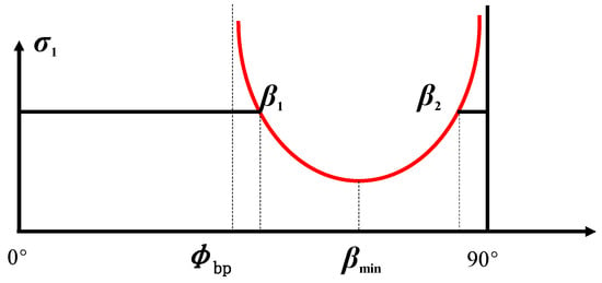
Figure 1.
Single weak plane criterion.
From Figure 1, one sees that as the angle between the fracture-plane normal and the axial load approaches either the fracture’s internal friction angle or , the fracture-plane strength tends toward infinity. Both Figure 1 and Figure 2 [22] show that the dip angle βmin at which the peak strength is minimal is the average of β1 and β2, as shown in Equation (4),
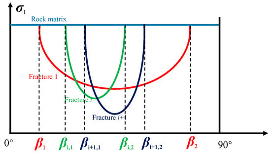
Figure 2.
Strength envelope of multi-weak plane rock in peak strength vs. bedding dip angle plane.
In real-world formations, the rock surrounding a borehole typically contains multiple fracture sets. Applying Jæger′s single weak-plane model to such conditions can lead to inaccurate collapse pressure predictions. To address this, we extend the single weak-plane mechanism by incorporating randomly oriented fractures in addition to one primary set of parallel fractures. This formulation leads to a new Multiple Weak-Plane Strength Criterion, which is developed under the assumption that stress perturbations from local block sliding can be neglected.
Similarly, we can plot the Multiple-Weak-Plane Criterion as a peak-strength versus fracture-dip envelope, as in Figure 2. Suppose in a given rock the i-th and (i + 1)-th fractures are distributed as shown at left in Figure 2; at right in Figure 2, the three strength envelopes represent the intact rock, the i-th weak plane, and the (i + 1)-th weak plane. It is evident that when multiple fracture sets exist, the overall strength is controlled by the weakest fracture set. Therefore, in fractured formations one should employ a Multiple-Weak-Plane Criterion to assess borehole instability. This criterion [22] can be written as Equation (5):
where denote its cohesion, internal friction angle, and the angle between the applied stress and its plane normal for i-th weak plane. The range of fracture dips [22] that lead to sliding on the i-th weak plane is given by Equation (6):
where is the normal stress on the i-th fracture plane, MPa; is the shear stress on the i-th fracture plane, MPa.
3. Borehole Instability Model in Fractured Formations
Once the formation is drilled, its original in situ stress state is disrupted, and stresses are redistributed around the borehole, producing stress-concentration effects. Figure 3 shows a schematic diagram of the stress calculation on the wall of a deviated well. Let σv represent the overburden pressure, and σH and σh denote the horizontal principal stresses. A coordinate system (1, 2, 3) is selected to coincide with the directions of the principal stresses σH, σh, and σv, respectively. For convenience, a Cartesian coordinate system (x, y, z) and a cylindrical coordinate system (r, θ, z) are established, where the Oz axis corresponds to the wellbore axis, and Ox and Oy lie in the plane perpendicular to the wellbore axis.
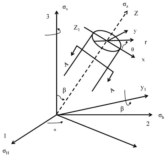
Figure 3.
Schematic diagram of coordinate transformation and sectional view for a deviated wellbore axis.
To establish the transformation relationship between the (x, y, z) coordinate system and the (1, 2, 3) coordinate system, the (1, 2, 3) coordinate system is rotated in the following manner (as shown in Figure 3): (1) First, rotate the (1, 2, 3) coordinate system about the 3-axis by an angle β; according to the right-hand rule, transforming it into the (x1, x2, x3) coordinate system. Here, β; is the angle between the wellbore azimuth (the angle between the projection trace of the wellbore axis on the horizontal plane and the true north direction) and the azimuth of the maximum horizontal principal stress (the angle between the direction of the maximum horizontal principal stress and the true north direction). (2) Then, rotate the (x1, x2, x3) coordinate system about the x2-axis by an angle α according to the right-hand rule, transforming it into the (x, y, z) coordinate system. Here, α is the wellbore inclination angle (the angle between the wellbore axis and the vertical direction).
The principal in situ stress coordinate system (1, 2, 3) is rotated to the coordinate system (x, y, z) as shown in Figure 3, resulting in the following stress transformation relationships [22]:
where [22]
[L] is the transformation matrix from in situ stresses to the wellbore Cartesian coordinate system, and [L]T is the transpose matrix of [L]. The drilling fluid in contact with the borehole wall induces thermal exchange—since the mud is cooler than the formation—and chemical interaction between mud additives and rock minerals, generating chemical stresses. Moreover, the difference between the original pore pressure and the column pressure of the drilling fluid drives filtration flow, producing seepage stresses. By the principle of linear superposition and using Biot’s effective-stress theory, the effective stress [22] at any point on the inclined borehole wall can be expressed as Equation (9).
where [22]
In the equations above, is the wellbore radius, in meters in m; Pw is the bottomhole hydrostatic pressure, in megapascals in MPa; Pp is the formation pore pressure, in megapascals in MPa; θ is the wellbore angle, i.e., the angle from a point on the wellbore circumference rotated clockwise to the coordinate axis Xb, in radians; α is the Biot effective stress coefficient, dimensionless, with a value range between 0 and 1; v is Poisson′s ratio, dimensionless; E is the elastic modulus, in gigapascals in GPa; αm is the volumetric thermal expansion coefficient of the rock matrix, in kelvin; T is the circulating temperature, in kelvin; To is the initial formation temperature, in kelvin; are the changes in radial stress, hoop stress, and axial stress, respectively, induced by osmotic pressure, in megapascals in MPa; Im is the reflection coefficient characterizing membrane efficiency, dimensionless, with a value range from 0 to 1; R is the universal gas constant, taken as 8.314 J/(K·mol); Vw is the molar volume of water, given as 18.104 m3; aw,df and aw,sh represent the chemical activity of the drilling fluid and shale pore water, respectively, where the chemical activity of fresh water is 1 and that of saltwater is less than 1.
After determining the wellbore stress distribution, we establish a wellbore instability prediction model for fractured formations using the multi-weak-plane strength criterion. Unlike conventional isotropic models, this criterion incorporates the strength reduction caused by weak planes, which depends on the angle β between the normal vector of a weak plane and the direction of the maximum principal stress. Consequently, when applying this criterion to wellbore stability analysis, the angle β must be calculated at every point around the wellbore. In the geodetic coordinate system, αbp,i and βbp,i represent the dip azimuth and dip angle of the i-th group of weak planes, respectively, with the Zbp,i axis direction being the normal direction of the weak plane. The normal vector [22] of the weak plane is given by Equation (11),
At a point on the wellbore wall, the minimum principal stress is the radial stress σr. In the wellbore Cartesian coordinate system, the Xb axis is rotated by a certain angle around the Zb axis to align with the direction of the minimum principal stress. The coordinate transformation [22] process from the Xb axis to the direction of σr is given by Equation (12),
where the direction vector of the Xb axis [22] is expressed as Equation (13),
The sine of the angle between the weak plane normal vector and the wellbore minimum principal stress vector is the angle between the weak plane normal and the maximum principal stress direction [22], as shown in Equation (14).
Based on the above principles, the critical drilling fluid density required to maintain wellbore stability can be determined by substituting the wellbore stresses into the multi-weak-plane strength criterion. Similarly, once the stress distribution at a distance r from the wellbore axis is established, the collapse pressure at that specific point can be calculated using the standard procedure for wellbore collapse pressure evaluation. For a specific bottomhole pressure Pw, if the collapse pressure at a point is greater than Pw, the point is marked in red (indicating instability); if it is less than or equal to Pw, it is marked in cyan (indicating stability). This allows for the visualization of the instability region around the wellbore within a certain radial distance under the applied bottomhole pressure.
The procedure for determining the wellbore breakout area is shown in Figure 4,
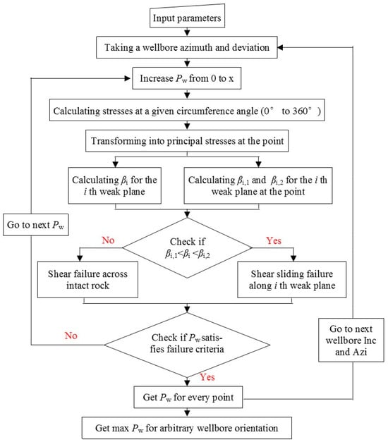
Figure 4.
The flow chart to calculate critical mud pressure using multiple weak planes criterion [26].
- (1)
- Initialize Parameters: Set the key geo-mechanical parameters, including wellbore orientation, the occurrence of bedding planes and fractures, their strength, and the radial distance from the borehole axis into the formation.
- (2)
- Calculate Wellbore Stress: For a given mud pressure, compute the stress field around the wellbore in polar coordinates using the stress transformation matrix and Equation (9).
- (3)
- Determine Principal Stresses: Transform the wellbore stress tensors into principal stresses.
- (4)
- Assess Failure Risk: To evaluate the potential for shear failure along fractures, calculate the angle between the maximum principal stress and the normal to the weak plane using Equation (14). Compare this value with the failure boundary angles derived from the multiple planes of weakness criterion in Equation (5).
- (5)
- Iterate for Critical Pressure: Apply the Newton–Raphson method to iteratively increase the mud pressure. For each pressure, the principal stresses are substituted into the weakness criterion. The critical lower mud pressure is identified as the highest value that satisfies the failure criterion at any point around the wellbore circumference.
- (6)
- Map the Breakout Limit: The wellbore circumference is scanned from 0° to 360° in 2° increments. The minimum mud pressure preventing failure is calculated at each angle. The highest of these values is selected as the overall breakout limit.
- (7)
- Define Failure Zone: The full breakout region is mapped by progressively increasing the radial distance from the borehole and repeating steps 2–6. A more detailed procedure can be found in Ref. [22].
4. Impact of Fractures on Wellbore Instability
Taking Well X in the Sichuan Basin as an example, the impact of the degree of fracture development on wellbore stability is studied. The in situ stress, pore pressure, and rock physical and mechanical parameters at a depth of 2438.40 m, i.e., the formation of Longmaxi are summarized in Table 1. Based on the data in Table 1, input into the wellbore collapse pressure calculation model established in this paper, while considering the effects of temperature, seepage, and chemical actions, the impact of the degree of fracture development on wellbore stability is studied.

Table 1.
The inputting in situ stress, pore pressure, and rock physical and mechanical parameters.
The acquisition of fracture occurrence information in oil and gas well formations primarily relies on the integration of multiple data sources such as logging, core analysis, and seismic data: downhole acoustic and electrical imaging logs (e.g., FMI, UBI) can visually identify fracture dip and azimuth; oriented core analysis provides precise measurements of fracture density and filling conditions; 3D seismic attributes and anisotropy analysis are used to predict the macroscopic distribution of fracture systems between wells. These data are integrated through geostatistical methods to ultimately construct a 3D geological model that reflects fracture orientation, density, and development patterns, providing critical input parameters for borehole stability analysis and drilling design. Based on imaging log data (as shown in Figure 5) and laboratory experiments, this study obtained the developmental characteristics of formation fracture occurrence and rock strength. In Figure 5, the black curves and green symbols represent formation fractures. The position of the tadpole symbols along the track on the right indicates the dip angle of the fractures, while the orientation of the tadpole tails represents the azimuth of the fractures. The formation contains four sets of fractures, with the rock matrix strength and parameters for different fracture occurrences and strengths provided in Table 2.
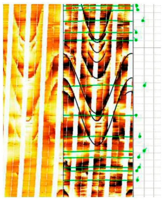
Figure 5.
Borehole imaging log of Well X.

Table 2.
Fracture occurrence and strength parameters.
4.1. Wellbore Collapse Pressure
Based on the model established in this study and using the parameters listed in Table 1 and Table 2, we obtained the collapse pressure distribution for varying degrees of fracture development. In the resulting contour map, the circumferential axis represents the wellbore azimuth, where the 0–180° direction aligns with the maximum horizontal principal stress. The radial axis denotes the well inclination, ranging from 0° (vertical well) to 90° (horizontal well). The color gradient, transitioning from dark blue to dark purple, corresponds to increasing collapse pressure. For intact formations, the wellbore collapse pressure cloud map is shown in Figure 6a. The cloud map is symmetrically distributed along the maximum and minimum horizontal principal stresses, with the collapse pressure ranging from 25.5 to 30 MPa. Wellbore stability is better for wells with inclinations below 50° in the direction of the minimum horizontal principal stress. When the formation has one fracture, the wellbore collapse pressure cloud map is shown in Figure 6b. Due to the presence of the fracture, the cloud map is no longer symmetrically distributed along the horizontal principal stresses, and the wellbore collapse pressure significantly increases, ranging from 28 to 33.8 MPa. When the formation has two fractures, the wellbore collapse pressure cloud map is shown in Figure 6c. The distribution characteristics of the cloud map change significantly, and the collapse pressure further increases, ranging from 29 to 37 MPa.
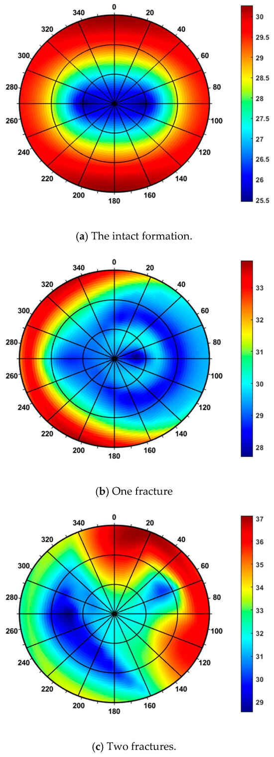
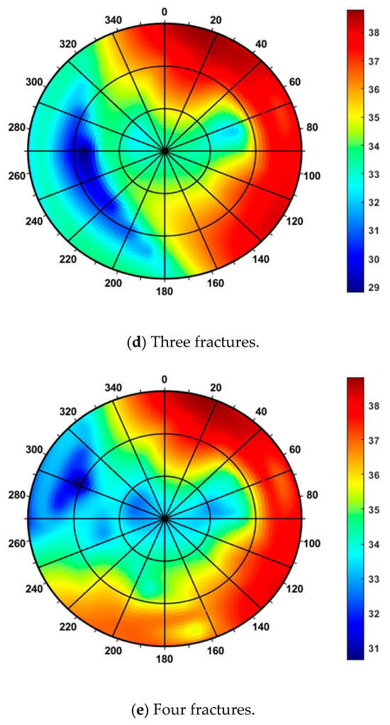
Figure 6.
Influence of fractures on wellbore collapse pressure (Unit: MPa).
When the formation develops three and four fractures, the wellbore collapse pressure cloud maps are shown in Figure 6d,e, respectively. As fracture density increases further, the range of wellbore collapse pressure remains largely stable, while the distribution pattern shown in the contour map continues to change significantly. Based on these observations, it can be concluded that when the formation contains more than three fractures, the wellbore collapse pressure value stabilizes. However, due to the variability in the contour distribution, determining the optimal well trajectory still requires case-specific analysis based on the actual fracture characteristics of the formation.
4.2. Instability Regions Around the Wellbore
In homogeneous reservoirs, there is no need to consider the influence of weak planes such as bedding; that is, the rock only undergoes matrix shear failure. For this mode, the instability regions around the wellbore typically appear in pairs and are symmetrically distributed, with the shape of the instability regions resembling “dog ears.” This phenomenon has been confirmed through laboratory experiments by Bautmans [34] and others [25,26,27,28,29]. Due to the stress concentration caused by in situ stresses, which mainly occurs in the direction of the minimum horizontal principal stress, the wellbore collapse locations also primarily extend into the formation in that direction. In shale reservoirs with well-developed bedding, the bedding planes are often treated as a set of parallel weak planes. The rock surrounding the wellbore is susceptible to shear–slip failure along these planes, resulting in significant wellbore enlargement. Unlike the typical “dog-ear” failure shape observed in homogeneous formations, the instability in such cases tends to produce a more rectangular wellbore cross-section. This phenomenon has been corroborated through thick-walled cylinder experiments by Okland and Cook [35], computer simulations by Zoback et al. [50] and imaging log data presented by Soroush [36]. While previous studies on shale wellbore stability have typically modeled a single set of weak planes, actual formations often contain multiple fracture systems. Research remains limited on wellbore instability in such multi-fractured formations. Furthermore, wellbore enlargement and related instability issues present serious challenges during cementing and completion. Severe wellbore washout can undermine cement integrity, adversely affecting subsequent multistage fracturing and long-term production. These issues directly impact the efficiency and economics of shale oil and gas development. In this study, we account for multiple fracture sets and systematically examine how the degree of fracture development influences instability regions around wellbores with different trajectories. Using a bottomhole pressure of 40 MPa and the parameters listed in Table 1 and Table 2, we analyze the distribution characteristics of instability zones around both vertical and horizontal wells under varying fracture densities.
The influence of fracture development on the instability zone around a vertical wellbore is illustrated in Figure 7. In the figure, the blue area represents the stable surrounding rock within a range of twice the borehole diameter around the wellbore, while the pink area represents the failed surrounding rock within a range of twice the borehole diameter around the wellbore. When the formation is considered a homogeneous and isotropic medium, shear collapse occurs along the direction of the minimum horizontal in situ stress, and the instability region takes on a “dog-ear” or crescent-shaped pattern. When a single fracture is present in the formation, the instability zone around the vertical wellbore remains unchanged (Figure 7b), indicating that this fracture has no impact on wellbore stability. Fracture 3 also has no significant effect; however, Fracture 2 causes deepening of the collapse zone in the direction of the minimum horizontal principal stress, suggesting that the orientation of weak planes significantly influences wellbore instability. Fracture 4 leads to a substantial enlargement of the instability region, resulting in a rectangular-shaped collapse zone after drilling, which differs greatly from the instability pattern observed when fractures are not considered.
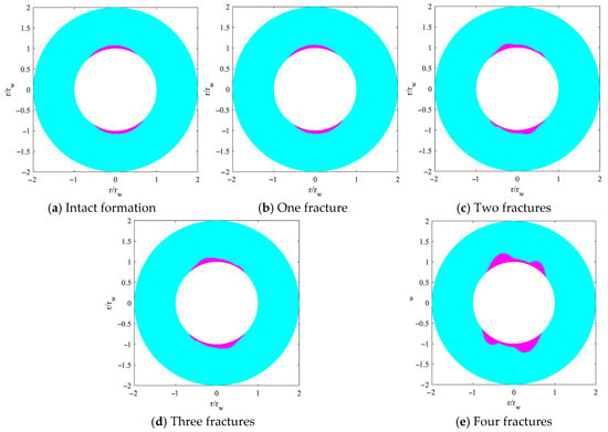
Figure 7.
Impact of fracture development degree on instability zone distribution around vertical wellbore.
Based on the data in Table 1 and Table 2, we similarly investigated the instability zone around a horizontal well under these geological conditions. Figure 8 shows the wellbore instability regions for varying degrees of fracture development. Compared to the intact formation, a single fracture (Fracture 1) causes only minor change in the instability zone. With two fractures present, however, the collapse zone extends deeper into the formation, and the location of maximum wellbore wall failure shifts away from the direction of the minimum horizontal stress. Notably, when four fractures are developed, the instability region expands significantly, resulting in a pronounced “rectangular” wellbore shape.
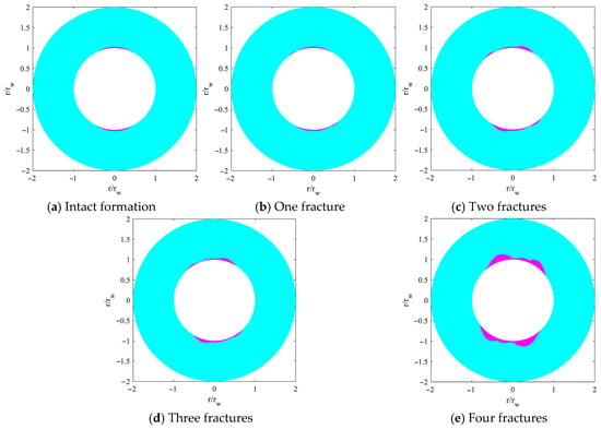
Figure 8.
Impact of fracture development degree on instability zone distribution around horizontal wellbore.
Figure 9 illustrates the instability zone around a horizontal well oriented along the maximum horizontal stress direction. It is evident that, as the degree of fracture development increases, the extent of the instability zone changes only marginally. Overall, the instability region for the horizontal well is significantly smaller than that of a vertical well; therefore, even in fractured formations, wellbore stability can be enhanced by optimizing the angle between the wellbore axis and the weak plane orientations.
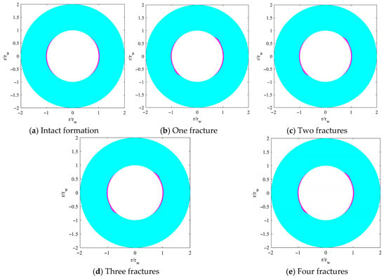
Figure 9.
Impact of fracture development degree on instability zone distribution around horizontal wellbore.
4.3. Field Application
Based on the findings of this study, the predicted lower limits of safe drilling fluid density for Well X in the Sichuan Basin at a depth of 2438.40 m—under varying degrees of fracture development—are presented in Figure 10. When no fractures are present, the predicted lower limit is only 1.06 g/cm3. Once three or more fractures are developed, the lower limit increases to 1.37 g/cm3, and it does not rise further with additional fractures.
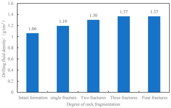
Figure 10.
Bar chart of predicted drilling fluid density for wellbore collapse in Well X of the Sichuan basin under different fracture development conditions.
Based on drilling records and logging data, the interval from 2390.05 m to 2445.19 m was drilled using mud densities ranging from 1.15 to 1.20 g/cm3. Significant borehole washouts were observed in this section, with enlargement rates surpassing 30% in certain intervals. Upon reaching 2445.19 m, frequent stuck-pipe incidents occurred, accompanied by considerable resistance during both tripping in and out. A heavy mud plug was circulated to recover cuttings, which included rock fragments up to 3 cm in size. Subsequent analysis incorporating offset-well geological data and in situ stress interpretation confirmed the presence of extensively developed fractures in this zone. The mud weight was therefore raised to 1.40 g/cm3, after which drilling proceeded smoothly and wellbore conditions improved significantly. These field observations align closely with the theoretical predictions.
5. Conclusions
Based on the present study, the following conclusions can be drawn.
In intact formations, the collapse pressure contours around the wellbore exhibit bilateral symmetry aligned with the principal horizontal stress directions. However, when strength anisotropy induced by weak planes is considered, this symmetry is disrupted. The resulting collapse pressure distribution becomes complex and trajectory-dependent, showing no clear geometric regularity.
As fracture density increases, the required collapse pressure rises accordingly. Once three or more fracture sets are present, the collapse pressure tends to stabilize, though the spatial distribution of the contours continues to evolve. In such fractured formations, overall stability is governed by the weakest set of fractures. Therefore, ensuring the integrity of the most critical weak plane is crucial for maintaining wellbore stability during drilling.
In intact rock, shear-induced collapse typically occurs along the direction of the minimum horizontal stress, forming “dog-ear” or crescent-shaped failure zones. With increasing fracture density, these collapse zones penetrate deeper into the formation, and the locations of maximum wall damage deviate from the minimum stress direction. The instability region expands significantly, often adopting a distinct “rectangular” pattern—markedly different from that observed in non-fractured formations. Optimizing the angle between the borehole axis and the dominant weak-plane orientation can substantially improve wellbore stability.
Future research should focus on integrating machine learning algorithms with real-time drilling data and geo-mechanical models. Such integration could enable dynamic adjustments to mud weight and well trajectory in fractured intervals, enhancing both theoretical understanding and operational safety in complex drilling environments.
Author Contributions
Conceptualization, K.L.; methodology, K.L. and J.W.; software, K.L.; validation, J.S.; formal analysis, J.S.; investigation, K.L. and J.W.; resources, J.S., T.R. and J.W.; data curation, T.R.; writing—original draft, T.R., W.W., J.W. and K.; supervision, K.; project administration, K. and W.W.; funding acquisition, K. and W.W. All authors have read and agreed to the published version of the manuscript.
Funding
This paper is supported by the Project V of CNPC Major Science and Technology Project “Key Technologies for Large-scale Reserve Addition and Production Increase and Enhanced Oil Recovery in Conglomerate Reservoirs”: Research on Optimized and Fast Drilling Technologies for Conglomerate Reservoirs (Grant No. 2023ZZ24-05); Xinjiang Uygur Region “One Case, One Policy” Strategic Talent Introduction Project (Grant No. XQZX20240054), Xinjiang Uygur Region Key Research and Development Program Project (Grant No. 2024B01012), Xinjiang Uygur Region Key Research and Development Program Project (Grant No. 2024B01014).
Institutional Review Board Statement
All research activities were conducted in accordance with the ethical guidelines and principles outlined by the Committee on Publication Ethics.
Informed Consent Statement
All individuals involved in this study have provided their consent for the publication of the study findings. Any personal or identifying information that could potentially compromise privacy has been carefully removed or anonymized.
Data Availability Statement
The data presented in this study are available on request from the corresponding author. The data are not publicly available due to privacy.
Conflicts of Interest
Authors Kecheng Liu, Jiangang Shi, Tao Ren, Kanizati and Weiju Wang were employed by the Research Institute of Production Engineering, Xinjiang Oilfield Company. The remaining authors declare that the research was conducted in the absence of any commercial or financial relationships that could be construed as a potential conflict of interest. The Research Institute of Production Engineering, Xinjiang Oilfield Company had no role in the design of the study, the collection, analysis, or interpretation of data, the writing of the manuscript, or the decision to publish the results.
References
- Song, X.; Guo, Y.; Xiang, D.; Ju, P.; Tan, Q.; Liu, W. Multi-field coupling analysis of wellbore instability mechanism of water-based drilling fluid in Hutubi Anticline. Xinjiang Pet. Gas 2023, 19, 1–9. [Google Scholar]
- Zou, X.-W.; Zhou, T.; Li, G.; Hu, Y.; Deng, B.; Yang, T. Intelligent Inversion Analysis of Surrounding Rock Parameters and Deformation Characteristics of a Water Diversion Surge Shaft. Designs 2024, 8, 116. [Google Scholar] [CrossRef]
- Ma, W.-B.; Zou, W.-H.; Zhang, J.-L.; Li, G. Prediction of Shear Strength in Anisotropic Structural Planes Considering Size Effects. Designs 2025, 9, 17. [Google Scholar] [CrossRef]
- Zhang, M.; Wen, J.; Xu, Z.; Xu, Z.; Feng, J.; Zhao, X. Study of borehole stability of volcanic rock formation with the influence of multiple factors. J. Pet. Explor. Prod. Technol. 2024, 14, 3367–3382. [Google Scholar] [CrossRef]
- Merey, S. Geomechanical wellbore stability analysis for the wells drilled in the shallow sediments of the Mediterranean Sea. J. Pet. Sci. Eng. 2020, 186, 106714. [Google Scholar] [CrossRef]
- Wang, Y.; Liu, X.; Liang, L. Anisotropy and energy evolution characteristics of continental Zhangjiatan shale in Yanchang Formation, Ordos Basin. Lithol. Reserv. 2019, 31, 149–160. [Google Scholar]
- Hashemi, S.S.; Taheri, A.; Melkoumian, N. Shear failure analysis of a shallow depth unsupported borehole drilled through poorly cemented granular rock. Eng. Geol. 2014, 184, 63–72. [Google Scholar] [CrossRef]
- Ji, Y.; Wu, W. Overpressure-induced frictional slip of rock fractures. Eng. Geol. 2022, 301, 106589. [Google Scholar]
- Chen, X.; Tan, C.P.; Detournay, C. A study on wellbore stability in fractured rock masses with impact of mud infiltration. J. Pet. Sci. Eng. 2003, 38, 145–154. [Google Scholar] [CrossRef]
- Karakul, H.; Ulusay, R. Evaluation of strength anisotropy and empirical models for estimating strength of rock materials with inclined weak planes using block punch index test. Int. J. Rock Mech. Min. Sci. 2020, 127, 104220. [Google Scholar]
- Zhang, M.; Li, D.; Liu, J.; Zhang, D.; Zhang, Y.; Cui, K. The modification of Mohr-Coulomb criteria based on shape function and determination method of undetermined parameters. Mech. Mater. 2023, 185, 104772. [Google Scholar] [CrossRef]
- Haimson, B. Micromechanisms of borehole instability leading to breakouts in rocks. Int. J. Rock Mech. Min. Sci. 2007, 44, 157–173. [Google Scholar] [CrossRef]
- Al-Ajmi, A.M. Wellbore Stability Analysis Based on a New True-Triaxial Failure Criterion. Ph.D. Thesis, KTH Royal Institute of Technology, Stockholm, Sweden, 2009. [Google Scholar]
- Nwonodi, R.I.; Okoro, E.E.; Dosunmu, A. An equivalent time-dependent analysis for predicting horizontal wellbore instability in a reactive shale formation using the imbibition/diffusion principle. Geoenergy Sci. Eng. 2023, 228, 212019. [Google Scholar] [CrossRef]
- Tang, M.; Zhang, G.; He, S.; Kong, L.; Deng, F.; Lei, H. Analysis of seepage and temperature fields and their influence on collapse pressure while drilling in shale oil reservoirs. J. Pet. Sci. Eng. 2022, 208, 109523. [Google Scholar] [CrossRef]
- Yang, H.; Chen, H.; Li, Y.; Sun, W.; Zhou, P. Optimization and application of strength criteria for evaluating mechanical instability of wellbore drilling. Xinjiang Pet. Gas 2022, 18, 1–5. [Google Scholar]
- Feng, F.; Xie, Z.; Chen, S.; Li, D.; Peng, S.; Zhang, T. True triaxial unloading test on the mechanical behaviors of sandstone: Effects of the intermediate principal stress and structural plane. J. Rock Mech. Geotech. Eng. 2025, 17, 2208–2226. [Google Scholar] [CrossRef]
- Ma, T.; Chen, P. Prediction method for shear instability region around horizontal wells in bedded shale. Pet. Drill. Tech. 2014, 42, 26–36. [Google Scholar]
- Liu, Z.; Chen, M.; Jin, Y.; Yang, X.; Lu, Y.; Xiong, Q. Collapse calculation model for open-hole horizontal wellbores in formations with multiple weak planes. Acta Pet. Sin. 2014, 35, 371–377. [Google Scholar]
- Chen, P.; Ma, T.; Xia, H. Collapse prediction model for horizontal shale wells containing multiple weak planes. Nat. Gas Ind. 2014, 34, 87–93. [Google Scholar]
- Zeng, W.; Liang, L.; Liu, X. Evaluation of wellbore stability based on elastic strain energy strength criterion. Rock Soil Mech. 2018, 39, 719–726. [Google Scholar]
- Zhang, M.; Fan, X.; Zhang, Q.; Yang, B.; Zhao, P.; Yao, B.; Ran, J. Parametric sensitivity study of wellbore stability in transversely isotropic medium based on poly-axial strength criteria. J. Pet. Sci. Eng. 2021, 197, 108078. [Google Scholar] [CrossRef]
- Cheng, W.; Jin, Y.; Chen, M.; Xu, T.; Chen, G. A method for determining wellbore collapse pressure based on shale damage law. Oil Drill. Prod. Technol. 2014, 36, 37–40. [Google Scholar]
- Guo, J.; He, S.; Deng, Y. Initiation modes and pressures of hydraulic fracturing in elastoplastic formations. Chin. J. Rock Mech. Eng. 2015, 34, 2494–2501. [Google Scholar]
- Omotunde, O. Log based stress modeling and wellbore stability studies. In Proceedings of the SPE Annual Technical Conference and Exhibition, New Orleans, LA, USA, 30 September–2 October 2013. [Google Scholar]
- Zhang, M.; Fan, X.; Zhang, Q.; Yang, B.; Zhao, P.; Yao, B.; He, L. Influence of multi-planes of weakness on unstable zones near wellbore wall in a fractured formation. J. Nat. Gas Sci. Eng. 2021, 93, 104026. [Google Scholar] [CrossRef]
- Bradley, W.B. Failure of inclined boreholes. J. Energy Resour. Technol. 1979, 101, 232–239. [Google Scholar] [CrossRef]
- Zoback, M.D. Reservoir Geomechanics; Cambridge University Press: Cambridge, UK, 2010. [Google Scholar]
- Zhang, M.M.; Liang, L.X.; Liu, X.J. Analysis of the Influence of Different Rock Shear Failure Criteria on Wellbore Collapse Pressure. Chin. J. Rock Mech. Eng. 2017, 36, 3485–3491. [Google Scholar]
- Li, J.; Zhang, X. Active flow control for supersonic aircraft: A novel hybrid synthetic jet actuator. Sens. Actuators A Phys. 2019, 302, 111770. [Google Scholar] [CrossRef]
- Gao, R.; Kuang, T.; Meng, X.; Huo, B. Effects of ground fracturing with horizontal fracture plane on rock breakage characteristics and mine pressure control. Rock Mech. Rock Eng. 2021, 54, 3229–3243. [Google Scholar] [CrossRef]
- Zhang, X.; Li, J. Advancements and challenges of high-speed active flow control: Plasma actuators. Int. J. Heat Mass Transf. 2025, 252, 127481. [Google Scholar] [CrossRef]
- Fan, Z.; Song, X.; Wang, D.; Ayasrah, M.; Li, S. Poroelastic Solutions of a Semi-Permeable Borehole Under Non-Hydrostatic In Situ Stresses Within Transversely Isotropic Media. Int. J. Geomech. 2025, 25, 4024342. [Google Scholar] [CrossRef]
- Bautmans, P.; Fjær, E.; Horsrud, P. The effect of weakness patches on wellbore stability in anisotropic media. Int. J. Rock Mech. Min. Sci. 2018, 104, 165–173. [Google Scholar] [CrossRef]
- Okland, D.; Cook, J.M. Bedding-related borehole instability in high-angle wells. In Proceedings of the SPE/ISRM Rock Mechanics in Petroleum Engineering, Trondheim, Norway, 8–10 July 1998. [Google Scholar]
- Soroush, H.; Khlaifat, A.; Qutob, H. A New Approach to Identify Breakout Zones in Tight Gas Shale. In Proceedings of the SPE Middle East Unconventional Gas Conference and Exhibition, Muscat, Oman, 31 January–2 February 2011. [Google Scholar] [CrossRef]
- Deng, J.; Guo, D.; Zhou, J.; Liu, S. Chemo-mechanical coupling calculation model and numerical solution method for shale wellbore stress. Chin. J. Rock Mech. Eng. 2003, 22, 2250–2253. [Google Scholar]
- Mangeli, M.; Aram, F.; Abouei, R.; Mehdizadeh Saradj, F. A New Look at Excavation Techniques and Design of Rock-Cut Architectures. Designs 2022, 6, 64. [Google Scholar] [CrossRef]
- Liu, H.; Cui, S.; Meng, Y.; Han, Z.; Yang, M. Study on Rock Mechanical Properties and Wellbore Stability of Fractured Carbonate Formation Based on Fractal Geometry. ACS Omega 2022, 7, 43022–43035. [Google Scholar] [CrossRef] [PubMed]
- Gao, R.; Bai, D.; Yu, B.; Tai, Y.; Meng, X.; Zhang, W. Ground fracturing of multi-strata for strong ground pressure control in extra-thick coal seams with hard roofs: Numerical simulation and case study. Eng. Fract. Mech. 2024, 303, 110129. [Google Scholar] [CrossRef]
- Aregbe, A.G. Wellbore Stability Problems in Deepwater Gas Wells. World J. Eng. Technol. 2017, 5, 626–647. [Google Scholar] [CrossRef]
- Khan, K.; Altwaijri, M.; Ahmed, S. Wellbore Stability Beyond Mud Weight. In Proceedings of the SPE Middle East Oil & Gas Show and Conference, Richardson, TX, USA, 28 November–1 December 2021. [Google Scholar] [CrossRef]
- Khosravanian, R.; Aadnøy, B.S. Monte Carlo simulation in wellbore stability optimization. In Methods for Petroleum Well Optimization; Elsevier: Amsterdam, The Netherlands, 2022; pp. 439–475. [Google Scholar] [CrossRef]
- Ezati, M.; Azizzadeh, M.; Riahi, M.A.; Fattahpour, V.; Honarmand, J. Wellbore stability analysis using integrated geomechanical modeling: A case study from the Sarvak reservoir in one of the SW Iranian oil fields. Arab. J. Geosci. 2020, 13, 149. [Google Scholar] [CrossRef]
- Chen, X.; Tan, C.P.; Haberfield, C.M. Guidelines for efficient wellbore stability analysis. Int. J. Rock Mech. Min. Sci. 1997, 34, 50.e1–50.e14. [Google Scholar] [CrossRef]
- Abdollahipour, A.; Soltanian, H.; Pourmazaheri, Y.; Kazemzadeh, E.; Fatehi-Marji, M. Sensitivity analysis of geomechanical parameters affecting a wellbore stability. J. Cent. South Univ. 2019, 26, 768–778. [Google Scholar] [CrossRef]
- Li, Y. Research on drilling fluid technology for wellbore stability in deep formations of Santanghu Basin. Xinjiang Pet. Gas 2016, 12, 26–30+2. [Google Scholar]
- Yang, M.; Si, S.; Zhang, K.; Xi, M.; Zhang, W. Bridging the relationship between physical exercise and mental health in adolescents based on network analysis. PsyCh J. 2024, 13, 835–848. [Google Scholar] [CrossRef] [PubMed]
- Jiang, S.; Zhang, J.; Diao, K.; Liu, X.; Ding, Z. Research Advances in Solvent Extraction of Lithium: The Potential of Ionic Liquids. Adv. Funct. Mater. 2025, 35, 2423566. [Google Scholar] [CrossRef]
- Zoback, M.; Hickman, S.; Ellsworth, W. Scientific Drilling Into the San Andreas Fault Zone — An Overview of SAFOD’s First Five Years. Sci. Drill. 2011, 11, 14–28. [Google Scholar] [CrossRef]
Disclaimer/Publisher’s Note: The statements, opinions and data contained in all publications are solely those of the individual author(s) and contributor(s) and not of MDPI and/or the editor(s). MDPI and/or the editor(s) disclaim responsibility for any injury to people or property resulting from any ideas, methods, instructions or products referred to in the content. |
© 2025 by the authors. Licensee MDPI, Basel, Switzerland. This article is an open access article distributed under the terms and conditions of the Creative Commons Attribution (CC BY) license (https://creativecommons.org/licenses/by/4.0/).