Abstract
The growing penetration of renewable energy has reduced system inertia and damping, threatening grid stability. This paper proposes a novel control strategy that seamlessly integrates virtual synchronous generator (VSG) emulation with low-voltage ride-through (LVRT) capability for direct-drive permanent magnet synchronous generators (PMSGs). The unified control framework enables simultaneous inertia support during frequency disturbances and compliant reactive current injection during voltage sags—eliminating mode switching. Furthermore, the proposed strategy has been validated through both a single-machine model and actual wind farm topology. Results demonstrate that the strategy successfully achieves VSG control functionality while simultaneously meeting LVRT requirements.
1. Introduction
With the development of the global economy and population growth, energy issues have increasingly become one of the major challenges facing humanity. While the extensive use of fossil fuels has improved living standards to some extent, it has also caused significant impacts on the global climate and environment. Therefore, accelerating the development of renewable energy has become a consensus worldwide. Among these, wind energy has garnered considerable attention due to its advantages such as safety, cleanliness, high efficiency, and low cost [1].
However, as the penetration rate of renewable energy sources like wind power continues to rise, conventional synchronous generators in power systems are being largely replaced. This has led to a significant reduction in the rotational reserve capacity and inertia of the power system [2,3]. The decline in grid inertia can seriously impair the system’s ability to regulate frequency and voltage, thereby affecting the power quality of the grid [4]. To address this issue, researchers have proposed the concept of VSG, which incorporates the damping and inertia characteristics of traditional synchronous generators into power electronic control devices. This approach aims to simulate the damping and inertia support capabilities of conventional synchronous generators, thereby enhancing system stability [5].
Currently, the VSG control strategies in wind turbines can be mainly categorized into three types: rotor virtual inertia control, droop control, and load reduction control. Rotor virtual inertia control involves releasing or storing the kinetic energy of the wind turbine and rotor to provide transient frequency support. It introduces a virtual inertia loop into the control system, effectively adding an additional inertial load to the wind farm, making its inertia comparable to that of a synchronous generator [6]. This method can effectively improve the system’s frequency stability but only offers transient frequency support.
Droop control adjusts the power output of the wind turbine based on deviations in grid frequency and terminal voltage from their reference values, providing support for grid frequency and voltage while mimicking the frequency regulation and voltage control responses of synchronous generators [7]. In summary, both rotor virtual inertia control and droop control aim to enhance the wind farm’s response to system frequency and voltage variations. In practical applications, these two control strategies can be combined to improve the overall performance of wind farms and their capability to support the grid. References [8,9] propose that current-controlled VSGs utilize additional frequency variation signals to simulate the inertia and active frequency droop characteristics of a synchronous generators. Additionally, reactive power voltage droop characteristics are incorporated into the reactive power control loop to realize current-source VSG control. Reference [10] proposes a generalized VSG control strategy through controller pole configuration and parameter identification methods. Based on this approach, renewable energy generation systems can provide higher virtual inertia in islanded mode and achieve more accurate power tracking in grid-connected mode. Similarly, in [11], a current-frequency multi-objective optimization control based on model predictive control is utilized to deliver fast response virtual inertia. By predicting frequency deviation through a frequency response model, this approach improves frequency control performance compared to traditional methods. Adjusting the weighting coefficients allows for tuning the support capability for system frequency. In [12], the inner-loop current reference is adaptively modified based on variations in grid voltage and frequency. Additionally, a radial basis function neural network is employed online to adjust the VSG virtual inertia, effectively suppressing large frequency fluctuations.
As for load reduction control, it suggests operating wind turbines in a non-maximal power tracking mode, reserving part of the power capacity to support grid frequency regulation [13]. While providing reserve support, this approach reduces the utilization efficiency of wind energy.
VSG control simulates the characteristics of synchronous generators, enabling grid-connected inverters to perform both frequency regulation and voltage support, thereby enhancing system stability and grid acceptance. However, since the control objectives focus on active and reactive power, during grid voltage sags, the output current rapidly increases to maintain active and reactive power at reference values. If not properly limited, this could threaten the safe operation of power electronic devices. Conversely, overly restrictive limits may prevent wind turbines from providing proper reactive power support as required by national standards. This creates a conflict between VSG control and LVRT strategies, necessitating the development of combined control schemes that can ensure frequency stability during fluctuations and meet voltage support requirements during faults.
Virtual impedance control is commonly employed to enhance the LVRT characteristics of grid-forming renewable energy systems. Reference [14] employs adaptive virtual impedance and voltage feed-forward current-limiting methods. These approaches effectively suppress fault currents while maintaining the VSG’s dynamic frequency and voltage support capabilities during normal operation. Reference [15] proposes a dynamic power adjustment strategy integrated with an LVRT scheme. This method combines virtual impedance control with current limiter switching. It addresses overcurrent issues in grid-forming inverters while improving the system’s power angle stability. Reference [16] utilizes virtual impedance control to improve converter performance under various fault conditions. This achieves both fault current suppression and enhanced power synchronization. However, the virtual impedance-based control methods struggle to ensure maximum power output from renewable energy units. Reference [17] employs virtual resistance and phasor-based current-limiting methods to restrict steady-state fault current and transient impact current during faults. However, these methods “freeze” the reactive power regulator during faults, making it difficult to determine the precise reactive power output during such events. In [18], the fault occurrence time is first identified, and control strategies are switched during faults to provide reactive support. Nevertheless, due to differences in output variable types and states across various control modes, switching can cause significant transient currents. To mitigate this, reference [19] designs a smooth switching strategy that avoids current shocks during mode transitions, while designing and implementing such control schemes adds complexity.
In summary, existing research either fails to simultaneously satisfy the requirements for frequency regulation and LVRT in wind turbines or involves complex control logic. Given that most grid-connected wind turbines are grid-following types, this study focuses on PMSG-based grid-following wind turbines, applying the concepts of virtual inertia and droop control to develop a VSG control strategy. Furthermore, to endow the PMSG with LVRT capacity, a reactive-current priority limiting strategy is designed based on the VSG control framework, which avoids control mode switching during faults and prevents sudden current change. Finally, using the CloudPSS platform [20], simulation analyses under frequency disturbance and voltage drop scenarios demonstrate that the proposed control strategy enables the PMSG to provide both grid frequency support and LVRT capability. This approach allows for the control scheme retrofit of existing grid-following PMSGs, enhancing their dual functions of frequency regulation and fault ride-through, thereby improving overall system stability. The contributions can be summarized as follows:
- This paper proposes a pioneering control strategy that seamlessly integrates VSG with LVRT capability for PMSGs. This unified framework enables simultaneous inertia support during frequency disturbances and compliant reactive current injection during voltage sags, effectively eliminating the need for mode switching.
- Within the established VSG control framework, a specific reactive-current priority limiting strategy is designed to inherently provide LVRT capacity. This integrated approach prevents sudden current changes and ensures stable operation during grid faults without requiring a separate control mode.
- The proposed strategy is rigorously validated through simulations of both a single-machine model and an actual wind farm topology using the CloudPSS platform. The results demonstrate that the strategy successfully equips grid-following PMSGs with dual functionality for frequency regulation and fault ride-through.
2. VSG Control Strategy of PMSG
2.1. Control Strategy for Machine-Side Converter and DC-Side Capacitor
At present, two structures are most commonly used for machine-side converters: one employs a fully-controlled rectifier circuit, while the other consists of an uncontrolled rectifier bridge combined with a Boost DC-DC converter [21]. In the fully controlled rectifier, the machine-side converter adopts a dual-loop control strategy with speed as the outer loop and current as the inner loop to achieve maximum power point tracking (MPPT) control. For the uncontrolled rectifier bridge with the Boost converter, the DC-side current is regulated by adjusting the duty cycle of the Boost converter, thereby controlling the electromagnetic torque and generator speed. This ensures the turbine operates at the optimal tip-speed ratio for MPPT. Both structures successfully implement MPPT control and have negligible impact on the conclusions of this study. Therefore, this paper focuses on the machine-side converter composed of the uncontrolled rectifier bridge with a Boost converter, while the obtained conclusions remain valid for both typical structures. In this case, the optimal generator rotor speed is given by
where represents the reference rotor speed of the generator under MPPT control; represents the optimal tip-speed ratio; represents the wind speed; R represents the wind turbine blade radius.
The MPPT control strategy of the machine-side converter is shown Figure 1, where the optimal generator speed reference is first calculated and then tracked through a PI controller to generate the DC-link current reference. Subsequently, a PI controller regulates the DC-link current to produce the duty cycle signal for the Boost converter, thereby achieving MPPT through this cascaded control structure. The DC-link current control equations is as follows:
where is the DC-link current reference; and are the PI control coefficients for rotor speed; is the actual rotor speed.
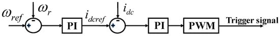
Figure 1.
MPPT control strategy of the machine-side converter.
Regarding the DC-link capacitor, this study incorporates an energy storage element on the DC side to provide the active power required for frequency support. Under this configuration, the DC-link capacitor voltage can be considered constant, which helps to emphasize the effectiveness of the grid-side control strategy under investigation [22].
2.2. VSG Control Strategy for Grid-Side Converter
To facilitate the improvement of control strategies for existing grid-following PMSGs, this study adopts the most widely used current-source grid-side controller for control strategy design. The grid-side converter employed consists of a controllable IGBT-based inverter bridge. In this work, the control objective of the grid-side converter is to output specified active and reactive power to actively support grid frequency and voltage. For grid-following grid-side converters, the grid-voltage-oriented vector control technique is typically employed. This approach aligns the d-axis of the synchronous rotating reference frame with the grid’s A-phase voltage vector. Consequently, the projection of the grid voltage on the q-axis becomes zero, expressed as
where and represent the d and q-axis voltages of the grid side, respectively; e represents the grid-side voltage vector.
The active power and reactive power injected by the grid-side converter into the system can be expressed as
where P and Q represent the output active and reactive power of the PMSG, respectively; and represent the output d and q-axis currents of the PMSG, respectively.
Based on the voltage orientation method described above, the active and reactive power outputs of the grid-side converter achieve decoupled control.
In terms of active power control, this paper adopts the commonly used virtual inertia control and droop control. The virtual inertia control emulates the inertial response characteristics of synchronous generators. For synchronous generators, a sudden increase in electromagnetic power leads to a decrease in rotational speed, thereby releasing the stored rotational kinetic energy in the rotor and slowing down the rate of system frequency decline. Under this control strategy, the active power output of the energy storage device is related to the rate of change of frequency, or in other words, the frequency variation trend. The relationship between the output active power and system frequency in virtual inertia control can be expressed as
where is the active power support under inertia control; is the active power compensation coefficient under inertia control; f is the system frequency.
The droop control is designed to emulate the droop characteristics of synchronous generators during primary frequency regulation. It responds to frequency deviations by adjusting the active power output of the energy storage system proportionally to the magnitude of the frequency deviation. The greater the frequency deviation, the larger the output active power provided, and this response persists throughout the entire primary frequency regulation period. The relationship between the output active power and system frequency in droop control can be described as
where is the active power support under droop control; is the active power compensation coefficient under droop control; f and are the actual and rated frequency of the system. As a result, the reference value of active power can be derived by
where is the reference active power of the PMSG; is the reference active power under MPPT control.
When implementing the VSG control strategy for grid-following PMSGs, there is no need to derive voltage phasor references from active and reactive power. Instead, the grid-side converter can be treated as a controlled current source, allowing direct generation of current references based on power references. Regarding voltage support, the national grid code has already established clear requirements for wind turbines. Therefore, no additional voltage support control strategy has been specifically designed for the system in this study. The proposed VSG control strategy, which integrates both virtual inertia and droop control, is illustrated in Figure 2. In Figure 2, P is the actual output active power of the PMSG and is the reference active current under VSG control. The active current under VSG control equation is as follows:
where and are the PI control coefficients for active power.
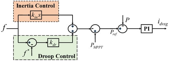
Figure 2.
VSG control strategy of the grid-side converter.
The grid-side control combines droop control with inertia control, representing a widely adopted VSG control strategy. In the subsequent sections, this study investigates an integrated control method that combines VSG strategy with LVRT capability. Under the proposed strategy, the PMSG can not only provide active power support to the grid but also deliver reactive power support that complies with national standards.
3. Integration of VSG Control and LVRT Control
For conventional PMSGs, when a voltage dip occurs at the generator terminals, the system will inject reactive current according to national grid code requirements to support the grid-side voltage. The required reactive power current can be represented as [23]
where is the required reactive current; is the reactive current coefficient; U is the terminal voltage of the PMSG; is the rated current of the PMSG.
The conventional VSG control strategy can effectively support system frequency during normal operation. However, when external faults cause terminal voltage sags, the PMSG’s attempt to maintain active power output leads to excessive active current that consumes converter capacity, preventing compliance with national standards for reactive power provision. To integrate virtual synchronous control with LVRT capability while maintaining both functionalities, this study develops a PQ-based control strategy with reactive current priority during voltage sags. This approach enables effective frequency support during normal operation while guaranteeing standard-compliant reactive current output during faults.
During voltage dips, the required reactive current is determined by (9), while the maximum allowable active current becomes constrained by the converter’s capacity limit according to
where is the maximum allowable active current; is the maximum allowable current of the converter.
Combining the VSG control strategy, the reference active current can be calculated as
where is the reference active current of the proposed control strategy.
After obtaining the active and reactive reference currents, the output voltage of the grid-side converter can be derived through the voltage control loop.
where and represent the output d and q-axis voltage of the grid-side converter; and represent the filtering resistance and inductance; and are the output d and q-axis currents of the PMSG; represents the angular frequency of the system.
As indicated in (12), after implementing PI control for the currents, the cross-coupling terms and must be incorporated to obtain the final voltage control signals. The expressions for and are given by
Therefore, the voltage control equations for the grid-side converter are as follows:
where and are the reference output voltage of the grid-side converter; , , and are the PI control coefficients for -axis voltage.
The structure of the PMSG and its control strategy adopted in this paper are illustrated in Figure 3.
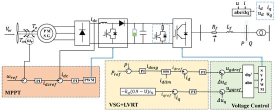
Figure 3.
Structure and control strategy of the PMSG.
In existing control strategies, the control objectives for voltage-source converters incorporating droop control and inertia control are typically active power and reactive power. When a fault causes a significant voltage sag, the VSG control strategy aims to deliver specified power, which substantially increases active current. Under such conditions, overcurrent occurs and occupies converter capacity. This prevents the PMSG from delivering the reactive current required by grid codes, creating a conflict with LVRT control requirements.
In contrast, the control strategy proposed in this chapter is based on a current-source converter architecture, with active and reactive currents as the control objectives. By adopting a reactive-current priority strategy, it seamlessly integrates conventional VSG control and LVRT control. During frequency disturbances, the VSG control strategy remains active while the LVRT strategy remains untriggered. When external faults cause voltage sags, the PMSG prioritizes delivering grid-code-compliant reactive current and utilizes the remaining capacity for frequency support. This approach effectively resolves the inherent conflict between traditional VSG control and LVRT requirements.
In the PMSG model, the maximum allowable current for the converter in this study is set at 1.1 times the rated current of the PMSG. Measurement filtering is implemented using a first-order inertial element with a time constant of 0.0011 s. Parameters of the PI controllers for each stage are listed in Table 1.

Table 1.
Parameters of the PMSG in the paper.
4. Simulation Verification
This section employs the CloudPSS electromagnetic transient simulation platform to analyze the proposed control strategy.
4.1. Frequency Disturbance Scenario
The test system used in this section consists of a PMSG, loads, a transmission line and a synchronous generator. The PMSG is represented by a single-machine equivalent model simulating ten units with a rated capacity of 1.5 MW each. This paper configures energy storage on the DC side. The rated power of the energy storage determines the PMSG’s active support capability. To prevent insufficient storage rating from affecting validation of the proposed strategy, the selected energy storage system for each PMSG is rated at 1 MW. The active load is 18 MW and the reactive load is 5 Mvar under steady-state conditions. The synchronous generator has a rated capacity of 325 MVA and a rotor inertia time constant of 1 s. The simulation step size for following case studies is set to 50 µs. A self-developed electromagnetic transient solver in CloudPSS is employed. An averaging switch model [21] is adopted for the simulation. The overall system structure is shown in Figure 4.
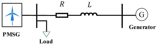
Figure 4.
Test system.
Since the PMSG does not enter LVRT operation in this case study, the response characteristics of three different models are compared: the conventional model with only LVRT control (LVRT model), the model with only inertial control (inertial model) [7], and the proposed model integrating both strategies (proposed model). At the 8th second of the simulation, the active load is abruptly increased to 28 MW to trigger a system frequency drop. In this case, the frequency and active power response characteristics of the three models are shown in Figure 5.
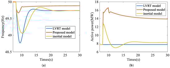
Figure 5.
Simulation results under the frequency drop scenario. (a) Frequency response characteristic. (b) Active power response characteristic.
Furthermore, a frequency rise scenario is considered. At the 8th second of the simulation, the active load is abruptly reduced to 13 MW, triggering a frequency increase. The frequency and active power response characteristics of the three models are illustrated in Figure 6. In these two cases, the active power of the energy storage system is shown in Figure 7.
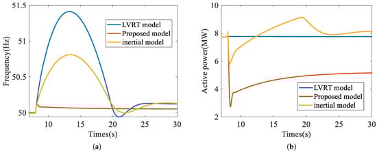
Figure 6.
Simulation results under the frequency increase scenario. (a) Frequency response characteristic. (b) Active power response characteristic.
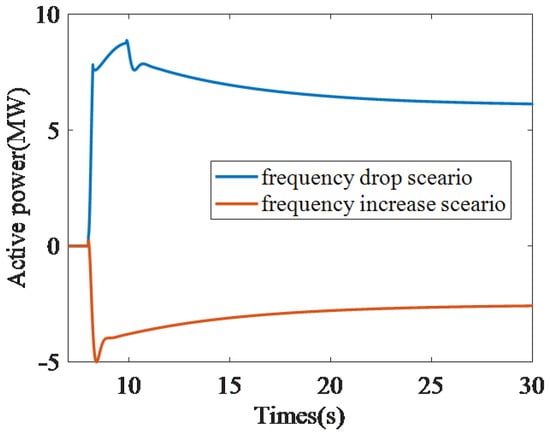
Figure 7.
Active power output of energy storage under frequency disturbance scenarios.
In the two cases, the maximum frequency deviation () and the deviation frequency at the 20th second after the frequency disturbance () for different models are summarized in Table 2. The simulation results demonstrate that, compared to the LVRT model and the inertial model, the proposed model not only rapidly provides active power support at the instant of frequency disturbance to mitigate the rate of frequency change but also reduces the ultimate magnitude of the frequency deviation. This validates the effectiveness of the proposed VSG control strategy.
Table 2.
Comparison of frequency characteristics of three models.
4.2. Voltage Drop Scenario
This section further validates the effectiveness of the proposed model under voltage dip scenarios. To facilitate the configuration of voltage dips, the test system shown in Figure 4 is modified by replacing the synchronous generator with an ideal voltage source. At the 8th second of the simulation, voltage dips are applied to 0.2 p.u. and 0.5 p.u., respectively, with a duration of 0.2 s for each dip. The response characteristics of three different models are compared, the LVRT model and the traditional VSG model considering both droop and inertia control (VSG model), as shown in Figure 8.
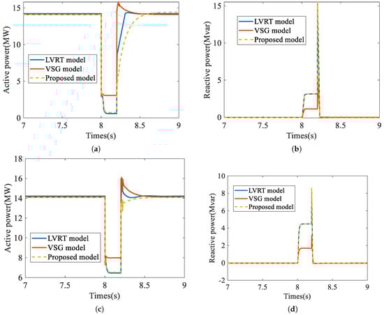
Figure 8.
Simulation results under the voltage drop scenario. (a) Active power (0.2 p.u.). (b) Reactive power (0.2 p.u.). (c) Active power (0.5 p.u.). (d) Reactive power (0.5 p.u.).
The conventional VSG control method attempts to maintain the active power at its reference value, leading to a rapid increase in active current during voltage dips. Under the constraints of converter capacity, the VSG model exhibits limited capability to deliver reactive power. As shown in Figure 8, the reactive power output of the VSG model during the fault is significantly lower than that of the LVRT model and the proposed model, failing to meet the requirements specified in the national standard for LVRT performance. The results are summarized in Table 3.
Table 3.
Comparison of reactive power characteristics of three models.
4.3. Wind Farm Scenario
To demonstrate the robustness of the proposed method, this chapter validates the approach based on the topology of an actual wind farm. The wind farm comprises 100 PMSGs with a capacity of 1.5 MW each, and its topology is shown in Figure 9. To improve simulation efficiency, the wind farm is divided into three clusters based on high, medium, and low wind speeds for equivalent modeling. Finally, simulations are performed based on these three equivalent units.
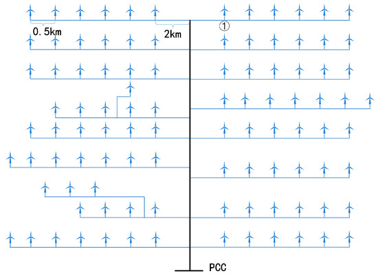
Figure 9.
Wind farm topology.
Under the frequency disturbance scenario, load disturbances are set at the point of common coupling of the wind farm. Active power drops of 20 MW are applied at the 8th, 9th, and 10th seconds of the simulation, respectively. The active power and frequency fluctuations of each simulation model are shown in Figure 10.
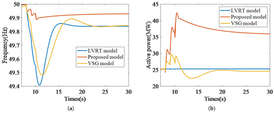
Figure 10.
Wind farm frequency drop scenario. (a) Frequency response characteristic. (b) Active power response characteristic.
The results indicate that the conclusions drawn from the wind farm scenario are largely consistent with those from the single-unit scenario, demonstrating that the proposed method effectively suppresses frequency disturbances.
Under the voltage dip scenario, a voltage drop to 0.2 p.u. was applied at the point of common coupling of the wind farm. The simulation results are shown in Figure 11.
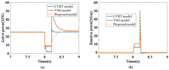
Figure 11.
Wind farm voltage drop scenario. (a) Active power response characteristic. (b) Reactive power response characteristic.
The results demonstrate that the proposed method can also provide reactive power support during faults that meets the requirements of the grid code. In summary, the proposed method is not only applicable to single-unit scenarios but also to wind farm scenarios, demonstrating its broad applicability.
5. Conclusions
In summary, this paper proposes a VSG control strategy incorporating active power droop control and inertia control based on a current-source PMSG. Furthermore, it integrates the VSG strategy with LVRT control, enabling the proposed model to not only provide active power support to the grid during frequency disturbances but also deliver reactive power in compliance with national standards during LVRT events. Moreover, the simulations under frequency disturbance scenarios demonstrate that the proposed model outperforms the LVRT model in providing active power support. Additionally, simulations under voltage drop scenarios confirm its capability to deliver reactive power compliant with national grid codes during LVRT events, a requirement that the conventional VSG model fails to meet. The proposed method can be applied to modify the control strategies of existing grid-following PMSGs, enhancing their grid support capabilities.
Currently, current-source PMSGs are generally equipped with LVRT capability but lack VSG functionality. The proposed control strategy integrates both capabilities. When retrofitting existing current-source PMSGs based on the proposed approach, it is necessary to incorporate droop control and inertia control into the outer power loop. After modifying the active power outer loop, the inner current loop strategy should be updated to reactive power priority control. Furthermore, to enable frequency support capability, energy storage components must be added on the DC side. Overall, retrofitting existing current-source PMSGs requires no additional hardware beyond DC-side energy storage. Only control strategy modifications are necessary. This makes the retrofit process relatively straightforward.
When providing grid support using the proposed control strategy, the PMSG must continuously monitor terminal voltage and system frequency. The accuracy of these measurements directly affects the support performance. Moreover, while this study focuses on the PMSG’s grid support capability, practical applications also require coordination with existing protection systems, which can be explored in future work.
Author Contributions
Conceptualization, Y.Y.; methodology, Z.W. (Zaijun Wu); software, Y.Y. and X.Q.; validation, Y.Y. and X.Q.; formal analysis, Y.Y., J.X. and X.Q.; investigation, Z.W. (ZaijunWu); resources, Y.Y.; data curation, Y.Y., Z.W. (Zijing Wan); writing—original draft preparation, Y.Y., Z.W. (Zetao Wei) and X.Q.; writing—review and editing, Z.W. (Zaijun Wu), Z.W. (Zijing Wan) and Z.W. (Zetao Wei); visualization, Y.Y., J.X.; supervision, Y.Y. and Z.W. (Zaijun Wu); project administration, Y.Y.; funding acquisition, J.X., Z.W. (Zijing Wan) and Z.W. (Zetao Wei). All authors have read and agreed to the published version of the manuscript.
Funding
This research was supported by the Science and Technology Project of State Grid Corporation under grant 4000-202425081A-1-1-ZN.
Data Availability Statement
The raw data supporting the conclusions of this article will be made available by the authors on request.
Conflicts of Interest
Authors Junjie Xiong, Zijing Wan, and Zetao Wei were employed by the State Grid Jiangxi Electric Power Co., Ltd. The remaining authors declare that the research was conducted in the absence of any commercial or financial relationships that could be construed as a potential conflict of interest.
Abbreviations
The following abbreviations are used in this manuscript:
| LVRT | Low-voltage ride-through |
| PMSG | Direct drive permanent magnet synchronous generators |
| VSG | Virtual synchronous generators |
| MPPT | Maximum power point tracking |
References
- Zhang, S.; Wei, J.; Chen, X.; Zhao, Y. China in global wind power development: Role, status and impact. Renew. Sustain. Energy Rev. 2020, 127, 109881. [Google Scholar] [CrossRef]
- Song, J.; Zhou, X.; Zhou, Z.; Wang, Y.; Wang, Y.; Wang, X. Review of low inertia in power systems caused by high proportion of renewable energy grid integration. Energies 2023, 16, 6042. [Google Scholar] [CrossRef]
- Faragalla, A.; Abdel-Rahim, O.; Orabi, M.; Abdelhameed, E.H. Enhanced virtual inertia control for microgrids with high-penetration renewables based on whale optimization. Energies 2022, 15, 9254. [Google Scholar] [CrossRef]
- Azmy, A.M.; Erlich, I. Impact of distributed generation on the stability of electrical power system. In Proceedings of the IEEE Power Engineering Society General Meeting, San Francisco, CA, USA, 16 June 2005; pp. 1056–1063. [Google Scholar]
- Sang, W.; Guo, W.; Dai, S.; Tian, C.; Yu, S.; Teng, Y. Virtual synchronous generator, a comprehensive overview. Energies 2022, 15, 6148. [Google Scholar] [CrossRef]
- Zhang, X.Y.; Zhu, Y.J.; Fu, Y. Wind-storage cooperative fast frequency response technology based on system inertia demand. Proc. CSEE 2023, 43, 5415–5429. [Google Scholar]
- Binbing, W.; Abuduwayiti, X.; Yuxi, C.; Yizhi, T. RoCoF droop control of PMSG-based wind turbines for system inertia response rapidly. IEEE Access 2020, 8, 181154–181162. [Google Scholar] [CrossRef]
- Sun, D.W.; Liu, H.; Gao, S.A.; Song, P.; Xu, P.L. Small-signal modeling and stability analysis of current-controlled virtual synchronous generators. Power Syst. Technol. 2018, 42, 2983–2993. [Google Scholar]
- Cheng, X.K.; Liu, H.; Tian, Y.F.; Zhao, F.; Sun, D.W.; Song, P.; Zhang, R.F. Review of transient power angle stability of doubly-fed induction generator with virtual synchronous generator technology integration syste. Power Syst. Technol. 2021, 45, 518–525. [Google Scholar]
- Rathnayake, D.B.; Razzaghi, R.; Bahrani, B. Generalized virtual synchronous generator control design for renewable power systems. IEEE Trans. Sustain. Energy 2022, 13, 1021–1036. [Google Scholar] [CrossRef]
- Qin, S.; Chang, Y.; Xie, Z.; Li, S. Improved virtual inertia of PMSG-based wind turbines based on multi-objective model-predictive control. Energies 2021, 14, 3612. [Google Scholar] [CrossRef]
- Yang, X.; Li, H.; Jia, W.; Liu, Z.; Pan, Y.; Qian, F. Adaptive virtual synchronous generator based on model predictive control with improved frequency stability. Energies 2022, 15, 8385. [Google Scholar] [CrossRef]
- Jiang, C.; Cai, G.W.; Yang, D.F.; Liu, C.; Sun, Z.L.; Liu, X.J. Under-frequency load shedding strategy for power system based on analytical frequency response model of doubly-fed wind turbines. Autom. Electr. Power Syst. 2023, 47, 108–118. [Google Scholar]
- Tang, Y.; Wang, B.; Chen, Y.; Jiang, X.; Du, Y. Research on Vsg Low-Voltage Ride-Through Control Strategy Under Symmetrical Power Grid Fault. In Proceedings of the 2025 44th Chinese Control Conference, Chongqing, China, 28–30 July 2025; pp. 1–7. [Google Scholar]
- Fang, H.; Yin, Y.; Xiao, Z.; Xiong, J. Improved Current Limiting Control for LVRT Strategy of Virtual Synchronous Generator. In Proceedings of the 2024 27th International Conference on Electrical Machines and Systems, Fukuoka, Japan, 26–29 November 2024; pp. 2049–2055. [Google Scholar]
- Ji, F.; Xu, Z. Enhancement of low-voltage ride-through capability for virtual synchronous generators based on virtual impedance voltage control. Energy Rep. 2023, 9, 406–415. [Google Scholar] [CrossRef]
- Shang, L.; Hu, J.B.; Yuan, X.M.; Chi, Y.N.; Tang, H.Y. Modeling and improved control of virtual synchronous generators under symmetrical faults of grid. Proc. CSEE 2017, 37, 403–412. [Google Scholar]
- Hu, W.Q.; Wu, Z.J.; Dou, X.B.; Hu, M.Q. Load virtual synchronous machine and its low voltage ride-through control. Autom. Electr. Power Syst. 2018, 42, 100–107. [Google Scholar]
- Chen, T.Y.; Chen, L.J.; Zheng, T.W.; Mei, S.W. LVRT control method of virtual synchronous generator based on mode smooth switching. Power Syst. Technol. 2016, 40, 2134–2140. [Google Scholar]
- Song, Y.; Chen, Y.; Yu, Z.; Huang, S.; Shen, C. CloudPSS: A high-performance power system simulator based on cloud computing. Energy Rep. 2020, 6, 1611–1618. [Google Scholar] [CrossRef]
- Zhang, Q.; He, J.; Xu, Y.; Hong, Z.; Chen, Y.; Strunz, K. Average-value modeling of direct-driven PMSG-based wind energy conversion systems. IEEE Trans. Energy Convers. 2021, 37, 264–273. [Google Scholar] [CrossRef]
- Pian, H.; Meng, K.; Li, H.; Liu, Y.; Li, Z.; Jiang, L. An adaptive control strategy for virtual synchronous generator based on exponential inertia and nonlinear damping. Energies 2025, 18, 3822. [Google Scholar] [CrossRef]
- China Electricity Council. Technical Specification for Connecting Wind Farm to Power System—Part 1: On Shore Wind Power; Standards Press of China: China, Beijing, 2021. [Google Scholar]
Disclaimer/Publisher’s Note: The statements, opinions and data contained in all publications are solely those of the individual author(s) and contributor(s) and not of MDPI and/or the editor(s). MDPI and/or the editor(s) disclaim responsibility for any injury to people or property resulting from any ideas, methods, instructions or products referred to in the content. |
© 2025 by the authors. Licensee MDPI, Basel, Switzerland. This article is an open access article distributed under the terms and conditions of the Creative Commons Attribution (CC BY) license (https://creativecommons.org/licenses/by/4.0/).