Abstract
Global warming has become a major challenge facing human society, with carbon dioxide (CO2) emissions being its primary driver. Carbon capture, utilization, and storage (CCUS) represents a promising technology for mitigating CO2 emissions from industrial and energy sectors. However, challenges such as high energy consumption, lengthy construction cycles, significant costs, and inadequate policy and market mechanisms hinder the widespread adoption of CCUS technology. This paper reviews the potential, applications, and related policies of CCUS technology, highlighting current research progress and obstacles. First, it provides a comprehensive overview of the CCUS technology framework, detailing developments and engineering applications in capture, transport, enhanced oil recovery, and storage technologies. Through global case studies and analysis, the review also examines advancements in CCUS infrastructure and technology strategies, along with operational experiences from major global projects. Second, it delves into the mechanisms, applications, and challenges of CCUS-related technologies, which are crucial for advancing their industrial deployment. It also outlines policy measures adopted by different countries to support CCUS technology development and large-scale deployment. Finally, it projects future directions for CCUS technology and policy development.
1. Introduction
Currently, the total global carbon emissions remain at a high level, and the achievement of carbon neutrality goals faces severe challenges. According to data from the International Energy Agency (IEA), global energy-related carbon dioxide emissions reached 4.08 billion tons in 2024, a record high, which is significantly out of step with the emission reduction pace required to meet the goal of “limiting the global temperature increase to well below 2 °C above pre-industrial levels by the end of this century” set in the *Paris Agreement* [1]. Even amid the global strategic process of accelerating energy transition, building a system with renewable energy as the mainstay, and exploring hydrogen economy and industrial coupling for multi-energy complementarity [2], the contradiction between the high carbon emission intensity of energy-intensive industries and the demand for emission reduction remains prominent. Carbon Capture, Utilization, and Storage (CCUS) technology, which can capture CO2 from emission sources, purify it for resource utilization such as enhanced oil recovery (EOR) and chemical production, or inject it into deep geological formations for permanent storage [3], has become an increasingly crucial component of the global climate governance strategy [4]. It can directly reduce existing carbon emissions, gain time for the research and development of low-carbon technologies, and alleviate the pressure of incremental emission reduction [5].
The CCUS technology system is a systematic project encompassing three key links: capture, transport, utilization, and storage. Among them, CO2 capture technology, as a critical part of the CCUS industrial chain, accounts for nearly 75% of the total cost. Diverse technical pathways for CO2 capture have been developed, including chemical absorption, physical adsorption, and membrane separation [6], but these technologies vary significantly in terms of capture efficiency, energy consumption, and cost structure. The CO2 transport link is essential for connecting capture sources to storage or utilization sites, and its efficiency and safety directly affect the operational performance of the CCUS system. The main current transport methods include pipelines, tank trucks, and ships [7], with the selection of transport mode requiring a balance between safety, economy, and large-scale potential. CO2-enhanced oil recovery (CO2-EOR) and storage technology, as the core link of the CCUS industrial chain with both economic value and environmental benefits, can improve oil recovery by injecting CO2 into oil reservoirs—leveraging mechanisms such as crude oil volume expansion, viscosity reduction, and reservoir pore structure optimization. Based on differences in formation pressure, three modes [8] are formed: immiscible displacement, near-miscible displacement, and miscible displacement. Unutilized CO2 is stored underground through physico-chemical mechanisms such as structural trapping and mineralization reactions, achieving the synergy of “oil production and emission reduction”. However, the current CCUS technology system still faces issues such as high capture energy consumption, high transport costs, and unstable storage efficiency, and there is an urgent need to break through these bottlenecks through technological innovation.
The development of CCUS technology largely depends on policy support from various countries. As a core policy tool [9], carbon pricing mechanisms enhance the economic viability of CCUS projects through market-based means, but their effectiveness is highly dependent on carbon price levels—only when the carbon price exceeds the cost of CCUS projects can market investment enthusiasm be effectively stimulated. International financing support and cooperation mechanisms provide capital and technical support for CCUS projects in developing countries, facilitating coordinated global decarbonization. Additionally, countries have adopted policy tools [10] such as tax credits, subsidies for demonstration projects, and five-year plan guidelines to provide guarantees for CCUS technology R&D and engineering applications. There are significant differences in policies across countries: the United States focuses on stimulating market investment vitality, with the 45Q tax credit as the core; the European Union, relying on the enhanced Emissions Trading System (ETS) and Innovation Fund, prioritizes technological leadership; China [11] mainly adopts a “top-down” approach of promoting demonstration projects and providing planning guidance to rapidly implement large-scale integrated projects. Nevertheless, global CCUS policies still suffer from problems such as insufficient stability, imperfect market-based mechanisms, and the need for stronger international coordination, which restrict the large-scale deployment of the technology.
Driven by positive policies from various countries, a variety of business models—ranging from oil and gas-driven, industrial cluster-based to power sector demonstration models—have emerged globally, demonstrating the technical adaptability and commercial potential of CCUS in different scenarios. Beyond traditional CCUS technology, Biomass Energy with Carbon Capture and Storage (BECCS) [12,13] and Direct Air Carbon Capture and Storage (DACCS) [14,15,16] have also received increasing attention from countries worldwide. The former refers to the capture, utilization, and storage of carbon dioxide generated during the combustion or conversion of biomass, while the latter involves directly capturing carbon dioxide from the atmosphere for utilization or storage. However, the engineering application of CCUS still faces core challenges: high energy consumption in the capture link and low efficiency of absorbents lead to high project operation costs; corrosion issues, leakage risks, and supercritical flow stability in the transport link pose severe tests to the safety and reliability of infrastructure; problems such as CO2 gas channeling, low storage rates, and leakage prevention and control in the storage and utilization links directly affect the environmental benefits and long-term safety of projects.
Based on this, this paper will conduct a critical review of CCUS from three dimensions: technical performance comparison, policy portfolio evaluation, and application challenge analysis. At the technical level, it will systematically sort out the principles and classifications of CO2 capture, transport, EOR, and storage technologies, and compare the capture capacity, cost structure, energy consumption, and storage efficiency of different technologies. At the policy level, it will analyze the policy frameworks of major global countries and evaluate the comprehensive impact of policies on CCUS deployment. At the application level, it will summarize the progress of global demonstration projects and typical application models, analyze the core challenges in engineering applications, and propose directions for future technological breakthroughs, suggestions for policy optimization, and innovative paths for the industrial chain.
2. CCUS Technology Introduction
2.1. CO2 Capture Technologies
2.1.1. Overview of CO2 Capture Technologies
CO2 capture technology encompasses a series of processes aimed at isolating CO2 from major emission sources, such as power generation and industrial operations, followed by its subsequent separation, collection, and compression. Based on the specific stage at which CO2 is extracted, CO2 capture approaches are generally classified into pre-combustion capture, post-combustion capture, oxy-fuel combustion capture, and direct air capture. A schematic representation of the overall process is provided in Figure 1 [17].
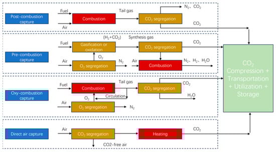
Figure 1.
Classification of CO2 capture technology.
(1) Pre-combustion Capture
Pre-combustion capture refers to the process of separating and capturing carbon dioxide before the combustion of fossil or biofuels. It is primarily employed in integrated gasification combined cycle (IGCC) power plants. The main procedure of IGCC involves: first, coal gasification to produce syngas containing hydrogen, carbon monoxide, methane, carbon dioxide, sulfur compounds, and nitrogen compounds; followed by a water-gas shift reaction, generating additional hydrogen and converting carbon monoxide into carbon dioxide; finally, the syngas undergoes desulfurization, denitrification, and subsequent decarbonization. Due to the high pressure and high partial pressure of CO2 at this stage, carbon dioxide can be captured more efficiently. The captured gas can be used as fuel for combined power generation and coal chemical processes. By integrating an efficient gas–steam combined cycle power generation system, the net power generation efficiency of IGCC can reach 43–45% with current technology, while pollutant emissions are only one-tenth of those from conventional coal-fired power plants, and water consumption is reduced to one-third to one-half. This offers significant environmental benefits. With technological advancements and increasing demands for carbon emission reduction, pre-combustion carbon capture is expected to play an important role in future carbon neutrality strategies. This capture method is one of the most cost-effective pre-treatment options and holds considerable potential in terms of efficiency and pollutant control. However, pre-combustion capture remains expensive and complex, and is not yet suitable for traditional coal-fired power plants, though it shows greater potential for new facilities. At present, large-scale coal gasification power generation faces challenges such as water scarcity, which restricts the construction and operation of IGCC plants and consequently hinders the global development of pre-combustion capture [18,19,20].
(2) Post-combustion Capture
Post-combustion capture technology involves separating CO2 from flue gas after fuel combustion. It is the most mature and widely applied CO2 capture method, extensively used in large stationary emission sources such as thermal power plants, cement kilns, and industrial furnaces [21]. Its main advantage lies in its compatibility with existing combustion facilities without requiring major modifications to the original processes, thus offering strong adaptability. However, a major challenge of this technology is the low concentration of CO2 in flue gas, typically only 10–15%, which results in a low driving force for separation, necessitates processing large volumes of gas, and leads to high energy consumption, large equipment footprint, and elevated operating and waste treatment costs. Presently, post-combustion capture mainly employs three technical routes: chemical absorption, solid adsorption, and membrane separation [22]. Among these, chemical absorption is the most mature, with typical absorbents including alkanolamine solutions (e.g., MEA, DEA), potassium carbonate solutions, and ammonia-based absorbents. Alkanolamine-based absorption has achieved commercial application and offers high selectivity and capture efficiency, but suffers from issues such as significant solvent loss, strong corrosiveness, and high regeneration energy consumption. Solid adsorption utilizes materials such as zeolites and activated carbon to separate CO2 through physical or chemical adsorption. Although this method has relatively low energy consumption, its adsorption capacity is limited and highly sensitive to temperature. Membrane separation technology employs selective permeable membranes to separate CO2, offering advantages such as simple equipment and low operational energy consumption. However, high membrane material costs and insufficient durability remain bottlenecks. Future development of this technology will focus on creating absorbents with lower energy consumption and corrosivity, improving adsorbent cycling stability, developing high-performance membrane materials, and reducing overall energy consumption through process integration and waste heat utilization, ultimately enabling economical and large-scale application of post-combustion capture [23,24].
(3) Oxy-fuel Combustion
Oxy-fuel combustion capture involves burning fuel with high-purity oxygen instead of air, resulting in flue gas composed mainly of CO2 and water vapor. After condensation, CO2 can be separated, thereby simplifying the capture process and significantly increasing CO2 concentration. This technology offers high capture efficiency, compatibility with retrofitting existing coal-fired units, and ease of scaling [25]. However, the oxygen production process relies on energy-intensive cryogenic air separation, which accounts for a substantial portion of the system’s energy consumption and remains a key economic constraint. These days, oxy-fuel combustion is considered one of the most commercially promising CCUS technologies, with several demonstration projects already in operation. Future development will emphasize reducing the energy consumption of oxygen production, advancing new technologies such as chemical looping and membrane-based air separation, to enhance overall economic viability and promote large-scale deployment [26].
(4) Direct Air Capture
Direct air capture (DAC) technology captures CO2 directly from the atmosphere through chemical or physical processes. As a typical negative emission technology, it offers advantages such as flexible siting, modular design, and easy integration with renewable energy sources, making it suitable for distributed CO2 emission management. However, the extremely low concentration of CO2 in the atmosphere (approximately 0.042%) leads to high energy demands and substantial costs. Current DAC technologies mainly employ liquid absorbents and solid adsorbents, with the latter being more widely used due to lower solvent loss and energy consumption. Research focuses on materials such as electro-swing adsorbents, metal–organic frameworks (MOFs), and hydrogen-bonded organic frameworks (HOFs), which have attracted attention due to their high specific surface area and tunable pore structures [27,28]. In the future, with innovations in materials, decreasing energy costs, and optimized system integration, DAC is expected to become a key technology for achieving carbon neutrality. Nevertheless, overcoming the challenges of high energy consumption and cost remains critical.
2.1.2. CO2 Capture Capacity and Performance Characteristics
At present, among various CO2 capture technology pathways, mainstream technologies such as chemical absorption, adsorption, and membrane separation have become the most widely applied commercial solutions due to their high technological maturity and good compatibility with existing energy infrastructure. These technologies exhibit distinct advantages and challenges in key performance indicators, including absorption/adsorption capacity, regeneration efficiency, and separation selectivity.
Chemical absorption is highly mature, and its performance enhancement primarily relies on the development of novel absorbents, aiming to overcome the limitations of conventional single-amine absorbents (e.g., MEA), which are constrained by limited absorption capacity and high regeneration energy consumption. Studies have shown that constructing new absorbent systems can significantly optimize performance. Liu et al. [29] developed a mixed-amine system (e.g., PZ/DETA/H2O), which, through component synergy, achieved a 42% increase in absorption capacity and a 9% increase in absorption rate compared with traditional MEA. Wang et al. [30] prepared a liquid–solid phase-change absorbent system by dissolving 1,4-butanediamine (BDA) in ethylene glycol (EG); its liquid–solid or liquid–liquid phase separation after reaction enabled exceptionally high absorption capacity, offering potential for low-energy rich-solution regeneration. Moreover, Lv et al. [31] developed non-aqueous/low-water amine systems (e.g., AMP-AEEA-NMP) that maintained high absorption capacity (1.65 mol CO2/kg amine) while demonstrating excellent cyclic stability (retaining 90% of capacity after four cycles), highlighting their reliability for long-term operation.
Adsorption relies on the reversible capture of CO2 by solid adsorbents, with core performance indicators including adsorption capacity, selectivity, and cyclic reversibility [32]. Developing high-performance adsorbent materials has been a research focus. Dinda et al. [33] prepared the metal–organic framework (MOF) ZrFu, which exhibited superior adsorption capacity (57–73 g CO2/kg) under mild conditions (30–90 °C), demonstrating great potential for temperature swing adsorption (TSA) applications. Modifications of conventional materials, such as introducing CuO active sites into activated carbon (AC) via direct solid-phase thermal dispersion to form CuO/AC composites (Chen et al. [34]), can simultaneously enhance CO2 adsorption capacity and selectivity, while maintaining good reversibility and stable performance over multiple adsorption–desorption cycles.
Membrane separation, as an emerging low-energy technology, has its performance primarily determined by CO2 permeability and CO2/N2 selectivity. High-performance membrane materials aim to balance high permeation flux and high separation precision. Li et al. [35] prepared polymer composite membranes (e.g., PSS-PEI), which, under near-industrial operating conditions (80–90 °C), achieved CO2 permeabilities of 820–1700 GPU and CO2/N2 selectivities of 395–460, demonstrating excellent overall separation performance. Jie et al. [36] fabricated graphene oxide-based membranes (e.g., GO/PEO) with extreme permeation performance, achieving a CO2 permeability of 1405 Barrer and good separation factors for CO2/H2 and CO2/N2 (10.9 and 43, respectively), indicating broad application potential in specific separation scenarios.
2.1.3. CO2 Capture Demonstration Projects
The global development of carbon capture and storage (CCS) technologies is characterized by a multi-regional and multi-pathway trajectory. In North America and Europe, supported by policy incentives and technological advances, demonstration and commercial projects such as Petra Nova, Boundary Dam, and the Century Plant have validated the feasibility of post-combustion and industrial-source capture, thereby accelerating the commercialization of CCS. From the perspective of technical indicators, these projects have established benchmarks for subsequent developments in terms of capture rate (85–95%), energy consumption (2.0–2.8 GJ/t CO2), and CO2 purity (>99%). Europe has further advanced cross-border storage and negative emission technologies through projects such as Northern Lights, Porthos, and HyNet/BECCS. In Asia and the Middle East, similar progress has been achieved. China has advanced industrial-scale demonstrations in pre-combustion, post-combustion, and oxy-fuel combustion capture technologies, including several million-ton projects, while optimizing absorbents and energy-saving processes. In particular, significant progress has been made in reducing regeneration energy consumption and enhancing CO2 purity. Japan’s Tomakomai project has demonstrated the safety of offshore geological storage, whereas South Korea and Southeast Asian countries have initiated demonstrations in the steel, power, and natural gas sectors. In the Middle East, leveraging its hydrocarbon industry, projects such as Al Reyadah, Ras Laffan (Qatar), and Uthmaniyah (Saudi Arabia) have integrated CO2-EOR. Emerging markets including Australia, Latin America, and Africa are also advancing CCS applications in industry and the oil and gas sectors, with examples such as Gorgon CCS, Moomba, and Petrobras’ subsalt reservoir project. Collectively, these initiatives demonstrate comprehensive coverage across major emission-intensive industries, charting a technological pathway from pilot to million-ton industrial deployment. This progress provides the foundation for achieving carbon neutrality and establishes a trajectory for the large-scale deployment of CCUS [37]. The projects are summarized in Table 1.

Table 1.
Typical Demonstration Projects of CO2 Capture.
(1) North America
North America represents one of the earliest and largest regions for CCS deployment, hosting several technologically advanced demonstration projects. As the world’s first large-scale CO2 capture project applied to a coal-fired power plant, the Petra Nova project in the United States once achieved an annual CO2 capture of 1.4 million tonnes, with a capture rate of approximately 90%, a regeneration energy consumption of about 2.7 GJ per ton of CO2, and a CO2 purity exceeding 99%. However, the project was suspended due to economic concerns, with costs estimated at around USD 60 per ton [38]. Canada’s Boundary Dam project, the first commercial post-combustion capture facility globally, has been operating reliably since 2014, thereby demonstrating the long-term feasibility of the technology. The project has achieved a capture rate of approximately 85%, with an energy consumption of about 2.5–2.8 GJ per ton of CO2 and a CO2 purity of around 99.5% [39]. The Century Plant in California, the world’s largest industrial CCS facility, has stored over 8 Mt CO2 since its commissioning in 2010, primarily in natural gas processing. The project has achieved a capture rate of approximately 95%, with relatively low energy consumption (<2.0 GJ per ton of CO2) owing to the high-concentration CO2 source, and a CO2 purity as high as 99.9%. Alberta’s Quest project, targeting the oil sands sector, applies saline aquifer storage with a capture capacity of 1 Mt CO2 per year, providing technical reference for similar applications. Moreover, the Canadian CCS Knowledge Centre, launched in 2023, is consolidating operational data from these projects to inform standard-setting across the industry. Collectively, these projects highlight North America’s leadership in CCS commercialization and industrial deployment, particularly in the oil and gas sectors.
(2) Europe
Europe has maintained a leading position in CCS development, underpinned by policy frameworks and financial support. Several large-scale demonstration projects are underway. Norway’s Northern Lights project represents the first cross-border carbon storage hub in Europe and is scheduled to commence operations in 2025, significantly strengthening regional CO2 management capacity. The capture rate is expected to exceed 95%, with an estimated cost of approximately USD 100–150 per ton and a designed CO2 purity of ≥99% The “Porthos” project in the Netherlands is scheduled for completion in 2026 and aims to become Europe’s first port-based carbon hub. It will transport CO2 from industrial sources in the Rotterdam area to storage sites in the North Sea via pipeline, with an annual storage capacity of 2.5 million tonnes and an expected capture rate of approximately 90% [40]. The United Kingdom is advancing negative emission technologies through the HyNet cluster and In BECCS projects [41]. Germany’s NORTH-CCS pilot project has conducted a 0.1 Mt offshore storage test in the Baltic Sea, providing technical validation for geological storage on the European continent. Together, these initiatives are not only advancing European CCS toward commercialization but also establishing cluster-based and cross-border cooperation models that offer valuable insights for subsequent large-scale deployment.
(3) Asia
In Asia, countries such as China, Japan, South Korea, and those in Southeast Asia and the Middle East are actively promoting CCS demonstration projects. China has undertaken industrial-scale demonstrations across pre-combustion, post-combustion, and oxy-fuel technologies. In the field of pre-combustion capture, the Huaneng Tianjin IGCC power plant was commissioned in 2012, and in 2015 a CO2 capture unit with a capacity of 60,000–100,000 tonnes per year was completed. It represents the largest demonstration project in China employing the methyl diethanolamine (MDEA) process, achieving a capture rate of approximately 85% and a CO2 purity exceeding 99.5%. In oxy-fuel combustion, Huazhong University of Science and Technology and its industrial partners established a 3 MWth pilot platform in 2011 and a 35 MWth demonstration platform in 2015, achieving key equipment development and parameter acquisition. In the field of post-combustion capture, China Energy Group has established several demonstration projects, including the Guohua Jingjie 0.15 Mt/a project and the Taizhou 0.5 Mt/a project, both commissioned in 2021. These projects employ integrated processes based on advanced technologies, with mixed-amine absorption as the primary capture method. The Guohua Jingjie project is designed to also accommodate emerging processes such as organic phase-change solvents and ionic liquid capture, achieving a CO2 capture rate of over 90%, a captured CO2 concentration exceeding 99%, and an estimated capture cost of approximately USD 33.71 per ton. The Taizhou project uses a self-developed multi-component mixed-amine solvent, reducing solvent regeneration energy consumption by over 35%, resulting in a capture energy consumption of less than 2.4 GJ per ton of CO2. It achieves a dry-basis CO2 purity of 99.5%, a capture rate of around 90%, and an estimated capture cost of approximately USD 36.52 per ton. Japan’s Tomakomai project, with a capture rate of approximately 90%, validated the safety of offshore geological storage, while also pioneering CCS-hydrogen integration with a target of commercial deployment by 2030. South Korea has conducted pilot-scale demonstrations in steel and coal power sectors to facilitate industrial decarbonization [42]. In Southeast Asia, Malaysia’s Kasawari CCS project is scheduled for operation in 2025 with a design capacity of 3 Mt CO2 per year, marking the region’s first large-scale CCS project. Indonesia and Thailand are also assessing the feasibility of CCS in conjunction with natural gas and chemical industries.
(4) Other regions
Beyond the aforementioned areas, emerging markets such as Australia, Latin America, and Africa are also actively pursuing CCS deployment. The Gorgon CCS project in Australia is one of the world’s largest carbon storage projects, with a designed total storage capacity of 40 million tonnes and a cumulative CO2 storage exceeding 7 million tonnes. Primarily serving the liquefied natural gas industry, the project achieves a capture rate of approximately 80%. Owing to the high CO2 concentration in the natural gas liquefaction process, its separation energy consumption is relatively low, with an estimated cost of USD 120–150 per ton [43]. The Moomba CCS project by Santos targets upstream oil and gas operations, contributing to regional industrial decarbonization [44]. In Latin America, Petrobras has implemented CO2 reinjection in Brazil’s pre-salt oilfields, achieving dual benefits of emission reduction and EOR, with a cumulative storage exceeding 60 Mt. In Africa, South Africa has initiated small-scale CCS demonstrations in the coal-fired power sector, while Nigeria is exploring CCS integration with natural gas utilization as part of its energy transition and carbon neutrality strategy. These initiatives underscore the diverse applications of CCS across different energy structures and industrial contexts, and highlight the accelerating engagement of emerging economies in low-carbon technologies, thereby contributing strategically to global emission reduction.
2.2. CO2 Transport Technologies
2.2.1. Overview of CO2 Transport Technologies
After being separated from flue gas, CO2 must be transported to storage or utilization sites. Therefore, establishing a safe, reliable, and cost-effective transport system is a critical component of carbon capture, utilization, and storage technology [45]. The phase state of CO2 varies with temperature, pressure, and the presence of impurities (e.g., CH4, N2, H2O), which directly influences the choice of transport method (see Figure 2). Pipeline transport generally adopts a single-phase mode-gaseous, liquid, dense phase, or supercritical-with the latter two being widely applied, particularly for long-distance and large-scale delivery. In contrast, truck and ship transport predominantly rely on the cryogenic liquid phase, which is more suitable for small-scale short-haul and long-distance offshore transport, respectively.
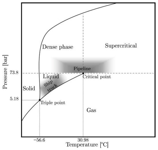
Figure 2.
Phase diagram of carbon dioxide (CO2) [46].
(1) Truck Transport
Truck transport represents the earliest applied method of onshore CO2 transport and primarily includes road and rail systems. Common loading modes involve dry ice, cryogenic insulated containers, and non-insulated high-pressure cylinders [47]. Typically, a single road tanker carries about 2–30 tons of CO2 at a pressure of 1.7–2.08 MPa, while a single rail tank can transport 50–60 tons at approximately 2.6 MPa. This technology is now relatively mature and is widely adopted in small-scale demonstration projects as well as an intermediate link connecting capture sites with pipelines or shipping systems. Future development will focus on enhancing loading and unloading efficiency, reducing cryogenic processing costs, and promoting efficient integration with large-scale pipeline and shipping networks, thereby facilitating multimodal transport solutions that support flexible access for distributed, small-scale capture points [48]. However, due to the additional compression and cryogenic treatment required for liquid CO2 transport, its cost remains significantly higher than that of pipelines, limiting its economic viability for large-scale and continuous CCUS deployment.
(2) Pipeline Transport
With the large-scale development of CCUS, pipeline transport has gradually become the preferred option for onshore CO2 delivery. Given CO2’s relatively low critical temperature and pressure, phase transitions can easily occur under varying environmental conditions; thus, single-phase transport is typically adopted in engineering practice [49]. Depending on the phase state, pipeline transport can be classified into gaseous, liquid, dense-phase, and supercritical modes. Among these, supercritical or dense-phase transport is considered most suitable for long-distance, large-volume applications. To date, multiple CO2 pipelines have been constructed in North America, Europe, and China, and the associated technical standards and operational expertise have become increasingly mature. Future development is expected to focus on interregional network interconnections, enhanced safety under complex geological and extreme climatic conditions, and seamless integration with port terminals and shipping systems [50]. However, the applicability of pipeline transport is largely restricted to onshore and nearshore areas. For cross-sea or offshore transport, high construction costs, complex seabed geology, and elevated safety risks pose significant challenges, limiting its flexibility in meeting the dispersed distribution of offshore storage or utilization demands. Figure 3 illustrates the process flow of the four transport modes.
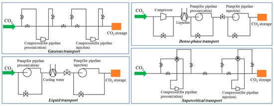
Figure 3.
Four process flows of CO2 pipeline transport.
(3) Ship Transport
Ship transport of CO2 draws on the mature transport experience of LPG (liquefied petroleum gas) and LNG (liquefied natural gas). CO2 is typically pre-liquefied and stored in specialized tanks, and transported through loading, shipping, unloading, and return-port processes. The transport mainly uses low temperature, high pressure, or semi-refrigerated methods. At present, CO2 transport is dominated by semi-refrigerated vessels operating at pressures of 1.4–1.7 MPa and temperatures of −25 °C to −30 °C. Compared to pipeline transport, shipping offers significant flexibility and can meet the demand for cross-national and cross-regional CO2 distribution. At present, small-scale demonstration projects are underway globally, with Europe constructing 10,000-t CO2 transport vessels, marking the early stages of commercialization. Future development will focus on large-scale, low-energy, and intelligent technologies, and will deeply integrate with offshore storage facilities and multi-port loading/unloading systems to support the construction of a global, large-scale CO2 transport network.
2.2.2. Comparison of Applicable Scenarios for Transport Methods
Each of the three transport methods has its own advantages and disadvantages, as shown in Table 2. The optimal CO2 transport solution needs to be determined through a comprehensive consideration of factors such as transport capacity, distance, cost, market factors, and the traffic layout along the transport route. Among them, tank truck transport is suitable for short-distance, decentralized transport scenarios, pipeline transport is ideal for large-scale land-based transport, and ship transport compensates for the limitations of pipeline transport in cross-sea and long-distance applications, offering strong flexibility for cross-sea transport.
Table 2.
Comparison of CO2 Transport Methods.
2.2.3. CO2 Transport Demonstration Projects
CO2 transport demonstration projects serve as a critical step in validating engineering feasibility and advancing commercialization, with their success directly influencing the effectiveness of CCUS deployment across the entire chain. As technical pathways become increasingly well defined, pipelines—owing to their mature engineering practice and pronounced economic advantages—have emerged as the preferred option for demonstration projects [51]. Globally, CO2 pipeline transport has accumulated decades of operational experience. North America has developed the most mature infrastructure, while Asia, Europe, and other regions have also initiated diverse demonstration projects, gradually forming distinct technological pathways and application models [52]. Key data on major long-distance CO2 pipelines worldwide are presented in Table 3.
Table 3.
Data related to major CO2 long-distance pipelines in the world.
(1) North America
North America represents the core region for global CO2 pipeline development. Since the 1970s, driven primarily by EOR, the United States has progressively established the world’s largest CO2 pipeline network. At present, more than 50 pipelines have been constructed, totaling approximately 8500 km in length and transporting 6.8 × 10⁸ t of CO2 annually [53]. About 80% of these pipelines operate in the supercritical phase, with design pressures generally maintained between 10–15 MPa. A representative project is the Cortez Pipeline, commissioned in 1984, which delivers up to 193 Mt of CO2 per year, making it the longest and highest-capacity CO2 pipeline worldwide to date [54]. In Canada, the Weyburn–Midale project utilizes a cross-border pipeline from the Dakota Gasification Plant in the United States to inject approximately 3 Mt of CO2 annually into oil fields for both EOR and geological storage [55]. As one of the earliest large-scale international CCUS demonstration projects, it represents a significant milestone in the global development of CO2 transport and storage.
(2) Europe
In Europe, CO2 pipeline development has primarily focused on demonstration projects associated with offshore oil and gas field storage as well as large industrial emission sources, resulting in diversified applications and mature technologies. The Snøhvit pipeline in Norway, the world’s first subsea CO2 pipeline, extends 153 km under marine conditions at a water depth of approximately 330 m, operating at around 15 MPa. It transports CO2 separated from an LNG plant to offshore oil fields, providing valuable experience for long-distance deepwater transport [56]. The Netherlands’ OCAP project delivers CO2 from refineries and ammonia plants via pipelines to nearby greenhouses, where it is used both to enhance plant growth and to substitute for conventional fuels, thereby achieving dual benefits of industrial emission reduction and agricultural productivity [57]. The Lacq project in France represents Europe’s first integrated CCS chain covering capture, transport, and storage [58]. It captures and pipelines approximately 60,000 t of CO2 annually, injecting it into a depleted deep gas reservoir. This project has served to validate long-term storage safety and monitoring technologies, thus advancing geological storage from the experimental phase toward commercialization.
(3) Asia
Although CO2 pipeline demonstration projects in Asia started relatively late, significant progress has been achieved in recent years, with increasingly diversified technological pathways. In China, the Qilu–Shengli Oilfield CCUS demonstration project adopts dense-phase transport at 12 MPa with a designed annual capacity of 1 Mt, providing valuable experience in high-pressure, long-distance pipeline construction and operation [59]. The Daqing Oilfield CCUS project employs a ~142 km pipeline to deliver captured CO2 for injection into reservoirs, with an annual capacity of about 2 Mt, demonstrating the feasibility of integrating onshore long-distance transport with EOR and storage. In Japan, the Tomakomai project uses a 1.4 km pipeline to transport CO2 captured from a refinery to an offshore reservoir, with a cumulative storage of around 0.3 Mt, making it a pioneering initiative in offshore CO2 storage in Asia [60]. Furthermore, the Kashiwazaki hydrogen–ammonia integrated project leverages the existing pipeline network to achieve CO2 capture, clean fuel production, and storage in depleted gas reservoirs, thereby promoting emission reduction through industrial chain integration [61].
(4) Other Countries and Regions
Beyond the regions mentioned above, other parts of the world are also actively exploring diversified modes of CO2 pipeline transport. In the Middle East, the Al Reyadah project in the United Arab Emirates is one of the world’s first commercial-scale CCUS projects [62]. It captures approximately 0.8 Mt of CO2 annually and delivers it in high-pressure gaseous form through a 42 km pipeline to the Rumaitha and Bab oil fields for EOR. In Turkey, the Bati Raman oil field has conducted CO2-EOR trials since 1986. The current annual injection volume is about 100 million m3, making it the earliest CO2 pipeline utilization project in the Middle East [63]. In the Southern Hemisphere, Australia’s Gorgon project represents the largest CCUS initiative in the region [64]. Its supporting pipeline and injection system are designed for an annual storage capacity of around 4 Mt, primarily handling CO2 separated during natural gas production, which is subsequently injected into deep reservoirs in a supercritical state for long-term geological storage.
2.3. CO2-EOR and Storage Technologies
2.3.1. Overview of CO2-EOR Technologies
CO2-EOR technology is primarily applied in the energy industry, especially in the oil and gas sector. In the context of gradually depleting global oil resources and increasing extraction difficulty, this technology provides an effective way to enhance the recovery factor of mature oil fields [65]. By injecting CO2 into reservoirs, the fluid properties and flow characteristics of the reservoir are improved, thereby increasing the recoverable amount of crude oil. The mechanisms of action mainly involve the effects of CO2 on the reservoir fluid and the reservoir itself. Injecting CO2 into the reservoir causes the crude oil volume to expand, reduces its viscosity, and improves its flowability [66]. CO2 can also extract light hydrocarbons from the crude oil, increase the oil density, and reduce the oil-water density difference, effectively alleviating the separation between oil and water. Furthermore, when CO2 dissolves in water, it increases the water’s viscosity and reduces its flowability, optimizing the flow rate ratio between oil and water [67]. In addition, the rocks in the reservoir undergo mineralization reactions with CO2 dissolved in water, adjusting the pore structure of the rocks, increasing their porosity and permeability, and enhancing the flowability of crude oil, thus improving oil recovery [68]. According to different pressure conditions, CO2-EOR is divided into three modes: immiscible displacement, near-miscible displacement, and miscible displacement [69]. The primary oil recovery mechanisms of these modes vary, as shown in Figure 4, and the oil recovery effects also differ. Table 4. compares the main recovery mechanisms and the advantages and disadvantages of each mode.
Table 4.
Main oil displacement mechanisms and their advantages and disadvantages under different modes.
When the formation pressure is lower than the minimum pressure required for CO2 and formation oil to reach miscible conditions, the drive mode is immiscible flooding. In this mode, there is still a significant interfacial tension between CO2 and formation oil, and only a portion of the injected CO2 can interact with the oil, leading to low oil recovery efficiency. In contrast, the immiscible flooding process does not require reaching a miscible state, so it has lower requirements for formation conditions and injection pressure, making it suitable for use in low-permeability and ultra-low permeability reservoirs where miscible pressure is generally high. During immiscible flooding, the main mechanisms of CO2 are oil swelling, viscosity reduction, and mineralization [70,71].
When the formation pressure near the injection well is higher than the miscible pressure, the formation pressure near the production well is lower than the miscible pressure, and the overall pressure is lower than and close to the Minimum Miscibility Pressure (MMP), the CO2 flooding mode is near-miscible flooding. This mode is primarily achieved through single-well CO2 huff and puff, and can achieve a higher recovery rate, but it requires specific injection pressure. When the displacement pressure near the injection point is higher than the miscible pressure, CO2 and crude oil form a miscible phase. During the displacement process, the pressure decreases, and when it reaches the bottom of the production well, CO2 separates from the crude oil. The main oil recovery mechanisms in this mode are reducing interfacial tension and gas dissolution drive [70,71].
When the formation pressure is greater than the CO2 miscible pressure, the CO2 flooding mode is miscible flooding, where the gas and liquid phases combine into a single phase, eliminating the interface and thus the interfacial tension. The advantage of CO2 miscible flooding is its outstanding oil recovery performance, with a theoretical recovery rate of up to 100%. However, its disadvantage is that it has higher requirements for formation conditions and injection pressure. The main oil recovery mechanisms in this mode include extraction and miscible effects [70,71].

Figure 4.
Main oil displacement mechanisms of CO2-EOR technology under different pressures [72].
Oil field CCUS projects have become the main direction for the commercialization and promotion of CO2-EOR technology. Through this approach, the costs of CCUS projects can be partially offset by the economic benefits of additional oil recovery. Compared to traditional water flooding technology, CO2 flooding has significant advantages in terms of increased recovery rates and environmental benefits. Regarding recovery improvement, Zhang et al. [73] pointed out that the Water-Alternating-Gas (WAG) technique is the preferred method for controlling CO2 mobility, which can be combined with mechanical techniques to help control the CO2 displacement volume, achieving the goal of increasing oil recovery. Al-Shargabi et al. [74] discovered that combining nanoparticles with surfactants can stabilize CO2 foam, making it more effective in enhancing recovery in the reservoir. In terms of process optimization, Li Yang [75] proposed development suggestions for key CO2 oil and gas recovery and geological storage technologies, emphasizing the research needs in CO2/oil/water/rock interaction mechanisms and numerical simulation techniques. He et al. [76] proposed an operational optimization workflow for CO2-EOR projects based on machine learning methods and greedy algorithms, and confirmed the accuracy, effectiveness, efficiency, and reliability of this workflow through application in a real project in northern China. Liu et al. [77] established an in situ method for measuring CO2 solubility in hexadecane under a wide range of pressure-temperature conditions, providing a solution for in situ detection technologies that measure the solubility of various fluids under broad conditions, supporting CO2-EOR and underground carbon storage operations.
2.3.2. CO2 Storage Technologies
CO2 storage technology is the final step in CCUS technology, mainly achieved through methods such as underground storage, ocean storage, and mineral carbonation storage. Lately, due to a series of issues such as the technical and economic challenges of ocean storage and seawater acidification, CO2 geological storage is the mainstream and the most feasible storage method [78]. CO2 geological storage involves injecting captured CO2 gas into suitable geological layers underground, using relatively impermeable rock layers, salt caverns, or depleted oil and gas fields, to prevent its release into the atmosphere and store it permanently underground, thereby reducing CO2 emissions into the atmosphere [79]. Suitable CO2 geological storage media include underground cavities, depleted oil and gas reservoirs, saline aquifers, coal seams, and others. As long as there is an impermeable rock layer preventing CO2 from escaping, any sufficiently deep formation with adequate pore space and permeability can be a potential storage space [80]. CO2 geological storage is mainly divided into two categories: physical storage and chemical storage. Figure 5 illustrates the storage mechanisms. Physical storage relies on geological structural characteristics to maintain CO2’s stable burial [81]. It can be further divided into structural storage and residual gas storage. Chemical storage is based on the reaction between CO2 and minerals or water in the formation, converting it into a stable form for burial. This type of storage includes dissolution storage and mineral carbonation storage. The pros and cons of each storage method are compared in Table 5. Structural storage refers to the phenomenon of gravity segregation after CO2 is injected into a saline aquifer [82]. The CO2 has a lower density than the formation water, and due to buoyancy, it moves toward the upper part of the structure. When it encounters an impermeable layer, it can no longer move and is trapped beneath the impermeable layer, forming a geological structural storage. Residual gas storage, also known as residual gas storage, occurs in underground environments at certain depths, where injected CO2 molecules, affected by pressure and buoyancy, enter the pore spaces and interact with the rock surfaces [83]. Dissolution storage occurs under specific temperature, pressure, and salinity conditions, where CO2 can dissolve into formation water, forming a stable aqueous solution [84]. These solutions are then safely stored in underground rock reservoirs, achieving long-term CO2 isolation. Mineral carbonation storage is a process in which injected supercritical CO2 reacts with formation water over time, generating carbonic acid, which then reacts with calcium, magnesium, iron, and other cations in the rocks in an acidic environment, forming insoluble mineral precipitates and permanently fixing CO2 in the formation [85].
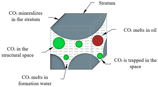
Figure 5.
Schematic diagram of storage mechanisms [86].
Table 5.
Comparison of the advantages and disadvantages of different storage methods.
A large number of experimental studies and reviews have been conducted both domestically and internationally on the microscopic mechanisms of CO2 geological storage, including the relationship between relative permeability, CO2 migration in rocks, and the factors affecting storage coefficients. Wang gaofeng et al. [87] proposed the concepts of theoretical storage capacity and effective storage capacity. The theoretical storage capacity is based on the basin block, while the effective storage capacity is based on the reservoir. Additionally, when calculating these CO2 storage capacities, the physical storage capacity should be considered as the standard. Shukla et al. [88] studied CO2 storage and caprock integrity, discussing the CO2-brine-rock interactions and introducing the CO2 migration rules in geological storage systems and reservoir rocks. Abidoye et al. [89] detailed the relationship between CO2 geological storage and two-phase flow in porous media, focusing on the storage capacity of aquifers, caprock integrity, the displacement of brine by supercritical CO2, simultaneous flow of free and buoyant CO2 phases, and various capture mechanisms. Bachu studied [90] the CO2 storage efficiency in deep saline aquifers, emphasizing the factors affecting CO2 injection and plume evolution (such as boundary conditions, driving forces, fluid properties, displacement characteristics in sedimentary rocks’ CO2-water systems, and aquifer properties), the storage efficiency coefficient for volume estimates, and the impacts of pressure and time on storage efficiency. Adu-Gyamfi et al. [91] investigated various combinations of hydrodynamic, geochemical, and geomechanical effects, and concluded that neglecting geochemical and geomechanical effects could lead to overestimating the CO2 storage potential. Ping-Yue et al. [80] using the Huang-3 block in the Ordos Basin as an example, conducted laboratory experiments to study the relationship between permeability and caprock breakthrough pressure in low-permeability reservoirs. They analyzed the effects of CO2 injection volume, recovery rate, injection methods, and injection pressure on the storage coefficient/percentage.
2.3.3. Comparison of Storage Efficiency
Storage efficiency is an important indicator for evaluating different geological storage technologies, primarily encompassing storage capacity and long-term storage stability. Among these, the cap rock conditions and reservoir properties are the key geological factors that directly determine the storage capacity and long-term stability of the storage site. This section will specifically assess the storage efficiency of three major geological storage technologies, focusing on the aforementioned cap rock conditions and reservoir properties.
Saline aquifers, with their broad distribution and large reservoir sizes, are ideal for CO2 storage. Their storage capacity depends on factors like reservoir thickness, porosity, permeability, temperature, pressure, and salinity, all of which affect available storage space and storage potential [92]. Long-term stability relies on cap rock integrity, which prevents CO2 leakage through capillary pressure differences. However, cap rock failure is a key risk. Hou Lianhua’s research [93] identified three processes that could lead to cap rock failure, providing insights for long-term stability. CO2-water-rock interactions also influence storage effectiveness, as physical properties of the reservoir alter the dissolution, retention, and migration of CO2 [94]. Richardson’s study [95] of Brazil’s Paraná Basin confirmed that optimal reservoir parameters significantly enhance CO2 storage efficiency, providing empirical support for the evaluation of saline aquifer storage efficiency.
Depleted oil and gas reservoirs are ideal for CO2 storage due to their well-defined geological conditions and proven sealing layers. The remaining pore space and well network after extraction offer a natural advantage for storage [96]. Storage capacity depends on reservoir volume, porosity, and available space post-extraction, while long-term stability relies on the integrity of the cap rock, which has been validated over decades [97]. However, well integrity poses a risk, as excessive injection pressure may trigger faults or leakage from old wells. Studies by On T et al. [98] on North American depleted fields identified wellbore cement aging and CO2 corrosion as major leakage causes, providing a foundation for stability assessment. CO2 storage effectiveness is also influenced by reservoir porosity, permeability, temperature, pressure, and the composition of oil and water, which affect CO2 dissolution, diffusion, and retention, offering key insights for quantifying storage efficiency. This provides a key reference for the quantitative evaluation of the storage efficiency of depleted oil and gas reservoirs
Coal seams can sequester CO2 through adsorption, with their capacity being 2–3 times higher than that of methane [99]. This process is often coupled with CO2-enhanced coalbed methane (ECBM) recovery. Storage capacity depends on coal seam thickness, rank, pore structure, and adsorption capacity, while stability is influenced by the seal integrity of the roof and floor layers and CO2 adsorption stability [100]. Low permeability in these layers prevents CO2 escape, and temperature or pressure fluctuations can cause CO2 desorption, while excessive injection pressure may rupture the coal seam and increase permeability. Jiang et al. [101] studied coal seams in the Qinshui Basin, China, revealing the effects of coal rank and roof/floor lithology on stability, and proposed an adsorption–desorption risk assessment model. After CO2 injection, the interactions between CO2, coalbed gas, water, and coal determine storage efficiency. Wang et al. [102] evaluated Bowen Basin coal seams in Australia, finding that for fat coal–coking coal with water content <5%, CO2 adsorption can reach 15–20 m3/t. Optimizing reservoir parameters enhances storage capacity and stability, providing a quantitative basis for efficiency assessment.
2.3.4. CO2-EOR and Storage Demonstration Projects
CO2-EOR and storage technology, as a carbon reduction technology that is beneficial to both the economy and the environment, has been widely applied in countries around the world. There are over 100 CO2-EOR and storage projects under construction or implementation globally. With some countries continuously deepening research and practice in CO2-EOR and storage technology, the global application map of this technology is expanding, providing more demonstrations for addressing climate change and achieving coordinated development between energy and the environment [103]. Typical CO2-EOR and storage projects are shown in Table 6.
Table 6.
Typical CO2-EOR Projects.
(1) North America
North America was the earliest to initiate CO2-EOR and storage projects. The United States was the first country to research and implement this technology. As early as 1958, the U.S. conducted CO2-EOR technology experiments in the Permian Basin. In 1972, Chevron implemented its first commercial CO2-EOR project at the Kelly–Snyder oil field in Texas. After the project began, data showed that crude oil recovery rates increased by about three times compared to before. In 2000, Canada launched the CCS-EOR project at the Great Plains Synfuels Plant. The project utilized combustion capture technology, with an annual capture capacity of 3 million tons. As an important attempt in Canada’s CO2-EOR and storage field, this project accumulated valuable experience for the Canadian energy industry in carbon reduction and improving oil recovery rates. By 2020, carbon capture projects were launched at the Alberta and Sturgeon CO2 Refineries in Canada, utilizing industrial separation technology from fertilizer plants, with an annual capture capacity of 1.4 million tons. This further advanced the depth and breadth of Canada’s application of CO2-EOR and storage technology.
(2) Asia
Although research in the Asia region started relatively late, it has developed rapidly in recent years. In 2003, China’s Daqing Oilfield EOR project was initiated, which accumulated valuable experience for the future development of CO2-EOR and storage projects in China. In 2022, China completed a million-ton-level CCUS demonstration project with an annual capture capacity of 1 million tons. China is constructing 3 million-ton-level CCUS-EOR demonstration projects at Daqing Oilfield and Jilin Oilfield, with the injection capacity expected to reach 500 × 104 tons per year and oil production estimated at 150 × 104 tons per year by 2025.
(3) Other Countries or Regions
In addition to the regions mentioned above, other regions are also actively exploring the development of CO2-EOR and storage technologies. In 2011, Brazil launched the CO2 capture and EOR project at the pre-salt oil fields in the São Paulo Basin. Brazil adopted membrane separation technology for CO2 capture based on the characteristics of its oil fields, with an annual capture capacity of 3 million tons. This project is a key initiative for Brazil to balance energy development and environmental protection, promoting the green development of its oil industry. In 2015, Saudi Arabia launched the Uthmaniyah CO2 enhanced oil recovery demonstration project, capturing CO2 through natural gas plant capture technology, with an annual capture capacity of 800,000 tons. This project reflects Saudi Arabia’s commitment to combining advanced CO2 capture technology with traditional oil production, helping to maintain the country’s oil industry advantage in the context of energy transition [104,105].
2.4. Full-Process Cost Structure Analysis
The full-process cost composition of CCUS technology shows significant differences among various links, and on the whole, it follows the distinct characteristic of “capture as the dominant factor, transport as the supplementary factor, and differentiation between storage and utilization”. The cost of each link is comprehensively affected by multiple factors such as technical routes, scale effects, geographical and geological conditions, as shown in Table 7 below.
Table 7.
CCUS Cost Structure.
The CO2 capture link is the most important source of costs for CCUS projects. This high proportion is mainly due to the huge equipment investment and high energy consumption involved. The core determinants of capture costs lie in the carbon dioxide concentration of the emission source and the capture technology adopted. For industrial processes with a high carbon dioxide volume fraction (>90%) (such as hydrogen production and chemical fertilizer production), due to the high purity of the gas, no complex purification is required to meet the subsequent transport and storage requirements, and the unit capture cost can be as low as $10–30/t CO2. On the contrary, for low-concentration emission sources (such as flue gas from coal-fired power plants, with a CO2 volume fraction < 20%) [106], energy-intensive separation technologies such as amine-based solvent (e.g., MEA) [107] regeneration are required, resulting in a sharp increase in costs to $40–120/t CO2. From the perspective of technical routes, pre-combustion capture deals with gas with a relatively high CO2 concentration (30–40%), leading to lower separation energy consumption and a cost of approximately $28–41/t CO2; post-combustion capture technology is mature but faces the challenge of low-concentration flue gas, with a unit cost of about $36–53/t CO2; while oxy-fuel combustion technology has a relatively high cost range of around $36–67/t CO2 due to the high energy consumption of air separation for oxygen production [108].
In contrast, the cost proportion of the CO2 transport link is relatively low. Pipeline transport is the most economical and mainstream method, and its cost shows a significant economies of scale effect, meaning that the unit cost decreases as the transport distance and volume increase. Studies [109] have shown that when the annual transport volume increases from 0.5–1 million tons to 15–30 million tons, the unit cost of a 400-mile pipeline can drop from $30–60/t CO2 to $10–20/t CO2. In addition, since CO2 pipelines usually need to withstand higher working pressures (>10 MPa), their pipe walls are thicker, and the material and construction costs can be approximately 25% higher than those of natural gas pipelines of the same scale [110]. Among other transport methods, tankers (road/railway) have high flexibility but are expensive in terms of unit distance cost, so they are only suitable for small-scale and short-distance scenarios; ship transport has cost competitiveness under conditions of long distances (>500 km) and large scales (e.g., annual transport volume of 5 million tons), with the unit cost being reducible to $5–10/t CO2, but it requires high upfront investment in port infrastructure.
The cost proportion of the storage and utilization link is approximately 10% to 25% of the full process, but its internal composition varies greatly depending on different objectives. Under the pure storage path, costs are mainly dominated by the geological conditions of the reservoir. High-quality reservoirs can use existing well networks and have strong injection capacity, with costs as low as $1–10/t CO2; while low-quality reservoirs require additional drilling and enhanced monitoring, which increases the cost to $20–40/t CO2 [111]. Although offshore storage has great potential, its cost is usually 40–70% higher than that of onshore storage due to the need for offshore platform and subsea pipeline construction.
In conclusion, the cost structure of CCUS technology clearly reveals that the CO2 capture link is the core bottleneck for the current large-scale and commercial application of the technology. Future technological R&D and policy support should prioritize reducing the high-energy-consumption capture costs, while at the same time promoting the improvement of the overall technical and economic efficiency of CCUS through optimizing pipeline network layout and exploring diversified storage and utilization models.
3. Challenges in CCUS Engineering Applications
3.1. Capture Stage: High Energy Consumption and Absorbent Efficiency
In the full CCUS chain, the capture stage remains the core of energy consumption and cost, with regeneration energy typically accounting for more than 70% of total operating expenses, making it a major bottleneck for large-scale deployment [40]. Traditional amine-based processes, while technically mature and highly efficient in CO2 absorption, require substantial steam input for regeneration. The energy consumption per ton of CO2 captured generally ranges from 3.0 to 4.0 GJ/t CO2, falling short of future low-carbon and low-cost targets. To address this, researchers have proposed novel materials such as composite absorbents, phase-change absorbents, and ionic liquid absorbents [54]. Composite absorbents introduce additives to improve thermodynamic performance, reducing regeneration energy to around 2.1 GJ/t CO2, but they are more complex and prone to corrosion and stability issues. Phase-change absorbents utilize phase separation mechanisms to lower energy demand, with experimental energy consumption between 1.6 and 2.87 GJ/t CO2; however, they remain at the laboratory scale, and stability challenges arise during scale-up. Ionic liquid absorbents, praised for their low vapor pressure and excellent solubility, face limitations in commercialization due to high viscosity, mass transfer resistance, and production costs [56].
Beyond the absorbents themselves, process optimization is another key avenue for improving capture efficiency [112]. Large-scale demonstration projects commonly adopt energy-saving measures such as interstage cooling, rich-solution split-flow, and mechanical vapor recompression (MVR) flash, enhancing heat recovery and fluid distribution efficiency. However, interstage cooling, while effective in reducing solvent regeneration energy, entails high equipment operation and maintenance costs [113]. Rich-solution split-flow demands precise pipeline design, increasing system complexity. MVR flash relies on efficient compression and heat recovery equipment, and its economic benefits are limited under low-load conditions. Load fluctuations in coal-fired power plants (30–100%) further complicate matters, causing instantaneous variations in steam demand and tower pressure of up to 20–30% and ±0.2 MPa, respectively. External factors such as ambient temperature, humidity, and coal quality differences make it difficult for existing automation control strategies to maintain stable and efficient operation under dynamic conditions [114].
In summary, the key challenge in the capture stage lies in balancing absorbent development with process optimization, while enhancing the system’s adaptability to complex operating conditions. Achieving low-energy, high-efficiency capture remains a central direction for the future development of CCUS technologies.
3.2. Transport Stage: Safety Risks and Monitoring Technology Bottlenecks
After CO2 capture, safe and efficient transport is a critical link for achieving large-scale storage and utilization [115]. At present, large-scale transport mainly relies on pipelines, which face multiple operational challenges such as corrosion, leakage, and flow stability. Pipeline corrosion is primarily caused by reactions between residual water and CO2 forming carbonic acid. If impurities such as H2S, SO2, NOx, or O2 are present, the corrosion rate increases significantly, and in severe cases, hydrogen embrittlement can occur, weakening the pipeline’s structural integrity. Under low-temperature conditions, water can also form hydrate crystals, leading to pipeline blockages, increased compression energy consumption, and localized mechanical fatigue [116]. To mitigate these risks, engineering practices typically employ high-alloy steels, internal linings, or anti-corrosion coatings, while strengthening drying and purification at the capture end; however, these measures inevitably increase both capital and operational costs.
Leakage risk is another core challenge in CO2 transport. CO2 is colorless, odorless, and non-flammable, but if it leaks, it can accumulate in low-lying areas and create an asphyxiation hazard, threatening personnel safety [117]. Sudden depressurization may cause CO2 to liquefy or form dry ice, increasing local stress and causing secondary damage. Long-term small-scale leaks can lead to soil acidification and changes in groundwater chemistry, producing cumulative impacts on ecosystems and agriculture. Current monitoring methods mainly rely on detecting anomalies in pressure and flow, but they lack sufficient real-time sensitivity for detecting small, sudden leaks.
Furthermore, transporting CO2 in supercritical or dense-phase states improves efficiency and reduces energy consumption, but stable operation depends on temperature, compressor strategy, and terrain variations [56]. Some pipeline sections may cross critical points, forming two-phase gas–liquid regions that cause flow fluctuations, pressure oscillations, or localized blockages, complicating operational scheduling. The economics of transport are also constrained by pipeline diameter design, transport distance, compressor station layout, geological conditions, and regulatory limits. Single-pipeline projects generally fail to achieve economies of scale, resulting in high unit transport costs, while land acquisition and cross-regional coordination further prolong construction timelines. In summary, balancing material durability, flow stability, economic efficiency, and high-precision monitoring remains a key technical bottleneck for CO2 transport.
3.3. Storage and Utilization Stage: Long-Term Stability and Leakage Prevention
In the storage and utilization stage, the long-term stability of CO2 and leakage prevention directly determine the emission reduction effectiveness of CCUS [57]. In applications such as EOR and geological storage, CO2 behavior within the reservoir is influenced by geological heterogeneity, fluid properties, and injection-production operations, introducing significant uncertainties. One of the most prominent issues is gas channeling. High-permeability interlayers, natural fractures, or artificial pathways in the reservoir can cause CO2 to migrate rapidly along the path of least resistance, bypassing large oil volumes, reducing EOR efficiency, and decreasing residual CO2 retention, which lowers overall storage rates. Additionally, if the injection pressure exceeds the reservoir’s fracture pressure, new fractures may form, further increasing the risk of gas channeling [59].
Low storage efficiency is another major challenge. Some CO2 is recovered during the EOR process, while a substantial portion that is not trapped may enter non-target formations, increasing subsequent separation and compression costs, and potentially creating leakage hazards [118]. The integrity of the reservoir caprock and wellbores is critical for storage safety. Geological movements can create micro-fractures or weak zones in the caprock. Wellbores are exposed to CO2 and water over the long term, which can corrode casing steel and cement; aging cement or construction defects may provide leakage pathways, allowing CO2 to migrate upward to shallower formations, reducing storage efficiency and threatening groundwater and ecological safety. Changes in injection pressure can also alter local stress fields, potentially reactivating dormant faults and providing migration channels for CO2 [119]. Reservoir adsorption and dissolution characteristics further affect long-term stability: sandstone has limited adsorption capacity, and CO2 solubility in crude oil or formation water fluctuates with temperature and pressure; under unstable conditions, CO2 may be released again, increasing leakage risks.
Overall, the core challenge in the storage and utilization stage is to enhance CO2 retention in the reservoir, ensure the integrity of caprock and wellbores, and establish long-term monitoring systems [104]. While seismic monitoring, pressure measurement, and tracer methods can provide some data, it is difficult to maintain continuous tracking over decades or centuries. Future research should focus on reservoir modification, injection-production optimization, material durability improvements, and long-term monitoring technologies to ensure the safety and reliability of CO2 storage and utilization.
4. International CCUS Policies
The advancement of CCUS technology relies heavily on policy support. Policies not only provide financial backing for technological innovation but also foster a favorable market environment, promoting collaboration and research and development between enterprises and research institutions. Several developed nations have taken action to curb greenhouse gas emissions. Countries like the United States and the European Union have accumulated substantial experience in deploying CCUS. The U.S. Infrastructure Investment and Jobs Act explicitly outlines financial support for CO2 capture technologies, particularly by expanding tax credits to encourage corporate investment in CCUS projects, thereby mitigating their economic risks. Additionally, the European Union’s European Green Deal underscores the necessity of accelerating CCUS technology commercialization. It proposes establishing multiple CCUS demonstration projects by 2025 and allocating funds to support technological R&D and innovation. These policies provide strong incentives for CCUS technology deployment, thereby driving its advancement.
4.1. Current Status of International CCUS Policy Development
Recently, CCUS technology is widely recognized as a key means to achieve carbon neutrality goals, with policy development accelerating and multiple countries intensifying their efforts. Nations are paving the way for CCUS technology research, development.
Authorized legislation and regulations provide a supportive environment for CCUS, typically involving the establishment of legal and regulatory frameworks for CCUS. These frameworks provide the legal foundation for effectively managing CCUS activities and safely and reliably storing CO2. In 2009, the European Union enacted the CCS Directive, the world’s first comprehensive legislation for CCS. This directive established a legislative framework for all CO2 geological storage projects across the CCS chain, regulating CCS projects throughout Europe through well-designed project parameters and creating an effective regulatory system for CCS initiatives [120]. In 2014, Norway’s Ministry of Climate and Environment amended the Pollution Control Regulations, adding provisions for CO2 geological storage to regulate CO2 injection oversight and clarify responsibility allocation. In 2024, Canada formally revised its Competition Act, incorporating provisions encouraging the introduction of CCUS equipment and incentivizing manufacturers to adopt carbon emission reduction technologies.
Financial support is one of the most effective means to stimulate the deployment of CCUS projects. Given the substantial upfront investment and high operational costs associated with CCUS technology, timely and robust financial backing can effectively reduce initial financial barriers and investment risks. This not only directly accelerates the implementation of individual projects but also drives technological innovation and cost reductions across the entire industrial chain through economies of scale, creating a virtuous cycle. In 2009, the U.S. Congress allocated an additional $3.4 billion for CCS under the American Recovery and Reinvestment Act (ARRA). In 2017, the UK government pledged £100 million in its Clean Growth Strategy for CCUS and industrial innovation to reduce costs [121]. In 2021, Alberta, Canada, allocated CAD 750 million from carbon tax revenues to support industrial energy efficiency improvements and CCUS-related projects.
International cooperation can effectively promote the development and deployment of CCUS technology, particularly for developing countries. Given the technical complexity and high costs of CCUS projects, progress in these nations often moves slowly. International collaboration can pool the world’s top intellectual and financial resources to jointly tackle key technological bottlenecks, share R&D outcomes, and significantly reduce redundant investments and trial-and-error costs. In 2021, Japan’s “2050 Carbon Neutral Green Growth Strategy” proposed advancing international cooperation to encourage bold corporate investment and innovative R&D, thereby achieving industrial restructuring and socioeconomic transformation. In 2023, the Canadian government partnered with the UK’s Carbon Clean Solutions to advance multiple CCUS projects in Alberta and Saskatchewan [122]. In 2024, Dutch offshore giant SBM Offshore signed a cooperation agreement with Norway’s Ocean-Power to develop floating power stations equipped with CCS capabilities.
4.2. Effective Analysis of Key National Policies
Taking the United States, the European Union, and China as case studies for CCUS policy analysis, Figure 6 compares CO2 emissions from fossil fuels and industrial production in these three countries with global emissions over the past two decades. It shows that while global carbon emissions continue to rise, emissions in the United States and the European Union have stabilized and are gradually declining, indicating that their emission reduction efforts have yielded significant results. The United States and the EU, as developed nations, possess extensive accumulated experience in CCUS technology and policy. China, a developing country and the world’s largest carbon emitter, initiated its CCUS-related policies relatively late but has since progressively refined them.
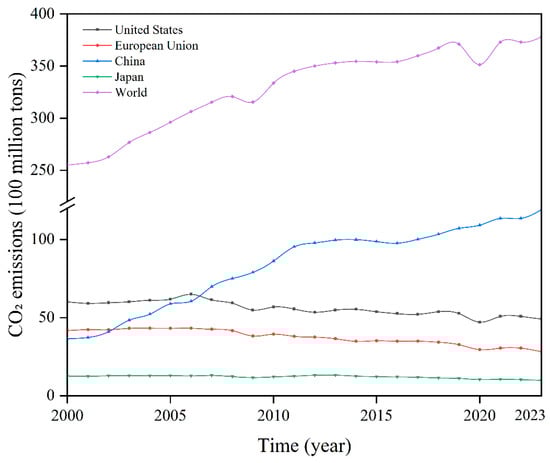
Figure 6.
Carbon Dioxide Emissions from Fossil Fuels and Industrial Production in Selected Countries and Worldwide [123].
The United States focuses on promoting CCUS technology deployment through financial support and tax subsidies, with the representative policy being Section 45Q. After years of revision and refinement, it now covers a broader range of CO2 capture projects, including power and industrial facilities, while offering tax credits of $85 per ton (for storage) and $60 per ton (for EOR). For DAC projects, Section 45Q offers tax credits of $180 per ton (for storage) and $130 per ton (for utilization) [124]. Section 45Q has effectively stimulated the deployment of CCUS projects in the United States. This provision significantly improves project economics, making previously unprofitable CCUS projects financially viable and attracting substantial private sector attention and investment. Furthermore, by offering differentiated subsidy levels based on technology type, it drives technological diversification and innovation, encouraging exploration and competition among various capture, utilization, and storage technologies, thereby promoting continuous iteration and advancement in CCUS technologies. Data clearly demonstrates this policy’s incentive effect. Before the bipartisan strengthening of Section 45Q in 2018, only about 10 commercial-scale CCUS projects were operational in the U.S. Following the amendment’s passage, project development accelerated rapidly. By the end of 2023, the number of commercial CCUS projects in the late development stage (i.e., having completed front-end engineering design or made a final investment decision) across the United States had exceeded 120 [125]. While Section 45Q effectively promotes CCUS deployment, its core “subsidy per ton” design introduces complex effects and challenges. Because subsidies are directly tied to the tonnage of carbon captured, facilities with higher carbon emissions and concentrations—such as coal-fired power plants—actually receive substantially greater subsidy benefits than lower-emission facilities like gas-fired plants. This mechanism may objectively delay the retirement of high-carbon facilities that should be phased out. Simultaneously, the subsidies reduce the marginal operating costs of CCUS facilities, potentially incentivizing production expansion and ultimately leading to an increase rather than a decrease in total emissions.
The European Union focuses on building a carbon market, using carbon taxes and carbon allowance trading to encourage companies to apply CCUS technology in actual production processes. The EU operates the world’s largest carbon trading market. In 2023, the EU carbon trading market auctioned 523 million allowances, with a total value reaching 44 billion euros, significantly promoting the deployment of CCUS projects [122]. The carbon market establishes a clear carbon price for CCUS-related enterprises, enabling direct comparison between CCUS emission reduction costs and conventional emission costs. When the carbon price exceeds CCUS costs, projects become economically viable, allowing businesses to assess project benefits more intuitively. Emission reductions generated by CCUS projects can be sold as allowances in the carbon market, generating revenue and becoming a key income source for these projects. Data indicates that following the EU carbon price entering a high-range period [126], the number of commercial-scale CCUS projects planned by member states has increased significantly. Simultaneously, funds raised through carbon market quotas can support CCUS technological innovation or finance large-scale demonstration projects, accelerating the advancement of CCUS technology. However, carbon prices fluctuate due to policy, economic, and energy market factors, introducing substantial revenue uncertainty risks for CCUS projects. Furthermore, carbon markets lack targeted incentives for CCUS projects—for instance, they fail to provide incentives for essential infrastructure such as pipelines and storage sites required for CCUS operations.
China focuses on providing a long-term, stable objective and formulating corresponding development roadmaps. For instance, the “China Carbon Capture, Utilization, and Storage Technology Development Roadmap (2019)” issued in 2019 reflects China’s top-down political system [124]. Its fundamental policy is the Five-Year Plan (FYP) issued by the central government, which serves as the overarching blueprint for national economic and social development over a five-year period. This FYP also constitutes the primary policy driving China’s CCUS deployment. Such a policy framework offers several advantages: it ensures the stability of long-term national development planning regardless of shifts in the ruling party’s stance or ideology, while also enabling efficient responses to emerging challenges and opportunities. This implies that if the central government demonstrates strong interest in CCUS for climate reasons, related research, planning, testing, and deployment will proceed rapidly, effectively advancing the implementation of large-scale integrated demonstration projects. However, this model also means that China’s CCUS projects remain predominantly government-investment driven. Market-based financing mechanisms require further refinement, and private capital faces significant barriers to participation in CCUS projects, making financing increasingly challenging for China’s CCUS initiatives.
Analysis reveals that policies can effectively accelerate the deployment of CCUS projects for several key reasons: First, they significantly reduce project risks. For instance, the U.S. Section 45Q tax credit and Canada’s Investment Tax Credit substantially improve project cash flow through direct subsidies or tax relief, covering high upfront capital expenditures and operational costs. This “output-based” incentive (subsidizing per ton of carbon sequestered) ensures the effectiveness of policy funding by directly linking project economics to emissions reduction outcomes. Second, they attract private capital and leverage market forces, using public funds to catalyze larger private investments. For instance, the EU Emissions Trading System provides clear asset attributes and price signals for CCUS emissions reductions. When carbon prices exceed CCUS costs, projects gain natural economic viability. Additionally, innovative financial instruments like carbon contracts for difference (CCFs) lock in carbon prices through long-term agreements between governments/institutions and project developers, effectively hedging market volatility risks and providing a solid foundation for bank financing. Third, policies drive technological R&D and cost reduction. While CCUS costs remain a primary barrier, policies play a guiding role in accelerating technological innovation and cost reduction. For instance, the EU directly funds large-scale demonstration projects through innovation funds to expedite technological iteration.
From the policies of these three countries, it is evident that the most successful CCUS policy frameworks are not the simple application of a single tool, but rather an organic combination of fiscal incentives, market mechanisms, regulatory frameworks, and infrastructure planning. However, the cornerstone for all these policy tools to be effective lies in providing long-term, stable, and predictable policy expectations. Establishing medium-to-long-term emission reduction targets through legislation and formulating a clear CCUS development roadmap aligned with these targets to instill firm market confidence is the most critical element in driving CCUS toward ultimate scale-up.
4.3. Analysis of Key Policy Instruments
Among the various policy tools driving CCUS demonstration projects toward large-scale commercial deployment, fiscal incentives have undoubtedly proven to be one of the most direct and effective means. The fundamental reason lies in the fact that the greatest obstacle facing CCUS projects is the high upfront capital expenditure and operational costs, which make them economically unattractive when competing with traditional processes or other emission reduction solutions [127]. Financial incentives effectively translate policy support into tangible project deployment momentum by sending direct economic signals, precisely addressing this core challenge. These incentives encompass measures such as tax subsidies, financial support, and carbon pricing.
Carbon pricing is an environmental economic policy tool whose core concept involves setting a price for greenhouse gas emissions [128], primarily carbon dioxide. It is primarily implemented through two mechanisms: carbon taxes and emissions trading systems. A carbon tax is a fee paid by emitters per unit of emissions, thereby increasing the pollution cost of goods and creating market incentives to reduce pollution and carbon emissions. Emissions trading systems operate by allocating a fixed quantity of greenhouse gas emission allowances to emitters. Carbon allowances can be traded among emitters, government agencies, or brokers. At the end of a compliance period, emitters exceeding their allocated allowances must purchase credits from those who emitted below their quotas, or face substantial penalties. A decisive economic relationship exists between carbon pricing and CCUS project costs. Carbon pricing mechanisms establish a clear price for carbon dioxide emissions, internalizing previously externalized environmental costs into enterprises’ actual operating expenses. This price signal serves as a critical benchmark for assessing the economic viability of CCUS projects. When carbon prices persistently exceed the unit operating and investment costs of CCUS projects, it indicates that the cost of emissions compliance has surpassed the cost of capturing, utilizing, or storing carbon dioxide. Under such circumstances, investing in CCUS transforms from a purely “cost expenditure” into a financially beneficial “hedging investment”. The project thereby gains fundamental commercial viability, capable of attracting market capital participation.
Tax subsidies refer to financial support indirectly provided by governments to eligible businesses or individuals through various preferential measures within the tax system [129]. This support aims to encourage specific economic activities or achieve certain policy objectives. Unlike direct cash disbursements, tax subsidies achieve their effect by reducing tax liabilities. Tax subsidies can directly improve a project’s cash flow, particularly for early-stage demonstration projects. At this stage, projects face high upfront investment and operational costs, and tax credit subsidies provide a clear, predictable additional revenue stream. This directly enhances the project’s cash flow position, improves the return on investment, and makes projects that were previously shelved due to poor economics financially viable.
Financial support refers to the provision of fiscal and financial resources by governments for CCUS projects [122]. Its core objective is to bridge the gap between the high upfront investment and operational costs of CCUS projects and their current market returns, thereby leveraging private capital. Beyond domestic government funding, the international community also provides critical support for CCUS technology deployment in developing countries through dedicated funds and multilateral cooperation platforms. International organizations establish specialized CCUS funds to provide financial backing, such as the Green Climate Fund, which offers grants, low-interest loans, and equity investments to significantly reduce project costs. Simultaneously, it provides targeted support to developing countries, funding preparatory work like feasibility studies and policy framework development. Furthermore, multilateral development banks leverage their substantial capital, expertise, and credibility to offer end-to-end support from project incubation to implementation. Beyond providing long-term, low-interest loans, they share best practices with enterprises and assist in establishing technical standards and regulatory frameworks. Beyond financial resources, the International Partnership for a Just Energy Transition (JPET), led by the G7 and the EU, serves as a multilateral financial cooperation platform for developing countries’ energy transitions. Funds are explicitly directed toward fossil-fuel-dependent regions, supporting CCUS facility construction while simultaneously investing in renewable energy and green industries. Funding can directly support costly infrastructure development, such as capture units, compressors, and pipelines, significantly lowering upfront investment barriers. Furthermore, government guarantees for project loans mean that if a project fails, the government will absorb part of the losses. This alleviates commercial banks’ primary concerns, encouraging them to finance CCUS projects and expanding financing channels for businesses.
5. Future Outlook
5.1. Future Outlook for CO2 Capture
The future development of CO2 capture technologies will focus on several core directions, including improving energy efficiency, reducing costs, advancing intelligent automation, innovating materials, and optimizing system integration. First, research and development of low-energy capture technologies should be intensified, promoting the application of novel absorbents, phase-change absorbents, and ionic liquid absorbents to significantly reduce energy consumption and operational costs associated with CO2 capture. Simultaneously, the development of advanced membrane separation and solid adsorption technologies, with enhanced selectivity and cycling stability, will help overcome existing material performance limitations and lay the foundation for industrial-scale deployment. Second, intelligent control systems are expected to become a major trend. By deploying data acquisition and sensing technologies, and leveraging modern machine learning and artificial intelligence algorithms to explore nonlinear relationships between operating parameters and capture performance, dynamic process optimization and predictive maintenance can be realized. This will drive the transformation of CO2 capture systems toward intelligent and automated operation, enhancing capture efficiency, reducing operational costs, and improving system safety and reliability. In terms of process optimization, oxy-fuel combustion technology is anticipated to achieve breakthroughs through energy-efficient innovations in oxygen production. Future efforts will focus on developing more efficient and energy-saving oxygen production methods, as well as integrated optimization of the entire oxy-fuel combustion capture system to enhance stability and economic performance while minimizing energy consumption in the oxygen production step. Moreover, materials innovation will serve as a key driving force. The development of high-performance adsorbents and novel membrane materials will remain a priority. Composite adsorbents show potential for improved CO2 adsorption capacity, selectivity, and cycling stability, while high-polymer–inorganic hybrid membranes can combine multiple advantages to achieve superior separation performance. Finally, policy and business model innovation is also essential. The establishment of sustainable economic incentives through carbon trading markets, carbon tax mechanisms, and government subsidies, coupled with strengthened international cooperation and technology sharing, will promote the standardization and large-scale deployment of CO2 capture technologies globally, providing robust support for achieving carbon neutrality
5.2. Future Outlook for CO2 Transport
Future development of CO2 transport technologies will focus on key areas such as material innovation, enhanced safety, flow stability optimization, intelligent management, and economic improvement. First, research and development should intensify on high-strength, corrosion-resistant, and hydrogen-embrittlement-resistant pipeline materials, combined with nanocoatings, self-healing materials, and strict impurity control technologies to enhance long-term durability and operational safety. Simultaneously, intelligent monitoring and control systems are expected to become a major trend. By deploying fiber-optic sensing, the Internet of Things (IoT), and artificial intelligence algorithms, real-time data on pressure, temperature, and flow can be collected, while nonlinear relationships between operational parameters and leakage risks are analyzed to enable dynamic optimization and predictive maintenance of pipeline networks, thereby improving system safety and reliability. Regarding flow control, research should prioritize the stability of supercritical and dense-phase CO2 transport, developing intelligent compression regulation, localized heating/cooling, and particle deposition management techniques to reduce flow resistance and energy consumption, and to prevent pipeline blockages and equipment damage. Through pipeline network optimization and multimodal transport strategies, capacity utilization for cross-regional, multi-source, and multi-sink CO2 transport can be increased while reducing costs. Furthermore, modular network design combined with full lifecycle management can synergistically enhance both economic efficiency and sustainability. Finally, innovation in policies, standards, and business models is indispensable. Leveraging carbon trading, carbon taxes, and government subsidies can promote cross-regional collaboration and technology sharing, providing essential support for large-scale global CCUS deployment and the achievement of carbon neutrality goals.
5.3. Future Outlook for CO2-EOR and Storage
The large-scale development and application of CO2-EOR and storage technologies in the future require addressing issues such as CO2 migration, low storage rates, and corrosion and leakage. To tackle CO2 migration, we will integrate high-precision monitoring to construct three-dimensional reservoir models, develop CO2-responsive intelligent plugging agents, and optimize well networks and injection parameters through dynamic control systems to enhance displacement precision. To address low storage rates, rock modification will enhance adsorption capacity, while temperature and pressure control will prolong dissolution retention time. Concurrently, corrosion-resistant cementing materials will repair caprock and cementing defects, paired with low-energy separation technology to enable CO2 recycling. For corrosion and leakage risks, an integrated surface-subsurface monitoring network will be deployed, featuring corrosion-resistant casing and fault pressure early-warning models, supported by emergency response and ecological monitoring systems. Additionally, we will explore a synergistic “oil recovery-storage-geothermal” model, leveraging renewable energy to drive full-chain decarbonization. We will refine technical standards and integrate with carbon trading markets, accelerating industrial application to balance benefits and safety.
5.4. Industrial Innovation in CCUS Applications
The development of CCUS is not merely an extension of traditional carbon reduction pathways, but also an important innovation that promotes the deep integration of energy systems. With the increasing share of renewable energy and the rise in the hydrogen economy, CCUS is gradually embedding itself into various stages of energy production, conversion, and utilization, thereby fostering a multi-level and cross-industry collaborative framework. Meanwhile, emerging approaches such as CO2 mineralization, biochar carbon storage, and DAC are demonstrating significant potential, providing new support for the transformation of CCUS from a single emission-reduction tool into a comprehensive climate solution.
In terms of renewable energy integration, CCUS can complement variable energy sources such as wind and solar power. By conducting CO2 capture and storage during periods of low electricity demand, CCUS not only contributes to emission reduction but also enhances grid regulation capacity, thereby improving the flexibility and stability of the energy system. At the same time, the development of the hydrogen economy expands the application space of CCUS. Blue hydrogen production relies on CCUS to reduce emissions, and when combined with hydrogen, it can also promote the development of carbon-recycling fuels such as synthetic methanol and aviation fuels, achieving high value-added utilization of carbon resources and extending industrial chains.
Furthermore, the convergence of CCUS with renewable metal fuels (e.g., iron, aluminum powders) presents a transformative pathway for constructing large-scale, near-zero emission energy systems. This synergy addresses systemic challenges inherent in a renewables-dominated future, including grid stability, industrial decarbonization, and long-duration energy storage. Within this coupled system, recyclable metal fuels act as high-density, carbon-free energy vectors, converting intermittent solar and wind power into dispatchable industrial heat and power through reversible oxidation-reduction cycles. CCUS, in turn, serves as the critical carbon management backbone, capturing residual CO2 emissions from upstream fuel production—such as when metal oxides are reduced using hydrogen derived from natural gas or biomass—and from hard-to-abate industrial processes supplied by metal fuel combustion. This deep coupling of an energy vector with a carbon management system offers a novel and robust approach for the synergistic decarbonization of power, industrial heat, and transport sectors, representing a forward-looking pillar for future carbon-neutral energy infrastructure.
From the perspective of sectoral and energy system coupling, CCUS infrastructure is increasingly becoming an essential component of the broader energy system. The integration of CCUS with high-emission industries such as power, steel, and chemicals has the potential to establish a multi-dimensional complementary network of “carbon grid–power grid–hydrogen grid.” Cross-sectoral infrastructure sharing and joint investment not only reduce construction and operational costs but also help disperse market risks, driving cross-industry win–win business models. Moreover, CCUS is experiencing a shift from policy-driven to market-driven deployment. Mechanisms such as carbon credits, green product premiums, and system service revenues continuously enhance industrial resilience and market competitiveness.
Regarding emerging directions, frontier CCUS pathways are revealing new development potential. CO2 mineralization enables the permanent transformation of carbon dioxide into stable minerals, realizing both emission reduction and resource utilization. Biochar carbon storage, based on agricultural residues, not only ensures long-term carbon fixation but also improves soil quality, delivering both ecological and climate benefits. Large-scale application of DAC is expected to provide crucial support for achieving net-zero and negative emissions targets. As these emerging pathways increasingly integrate with the CCUS system, their application scenarios will continue to expand, accelerating the evolution of carbon management from a single mitigation tool toward a comprehensive climate solution.
5.5. Future Outlook for CCUS Policy
The development and deployment of global CCUS technology are significantly influenced by government policies. Future deployment efforts should be tailored to the regional status of CCUS technology advancement and application. In countries lagging behind in CCUS deployment, governments should provide dedicated project funding or direct fiscal subsidies to support CCUS engineering demonstration projects. This will help accumulate technical and operational experience, identify challenges faced by enterprises, collect critical data, and lay the groundwork for future industry development. Once sufficient experience is gained, robust supply mechanisms encompassing pricing, trading, and quota protection must be established to incentivize corporate emissions reductions through CCUS. In regions with more mature CCUS industries, implementing tax breaks and preferential policies will encourage the full commercialization of CCUS projects, thereby accelerating the deployment and advancement of the technology.
6. Conclusions
Through a systematic critical review, this paper clarifies how three factors—technology, policy, and application—jointly influence CCUS projects. Based on an assessment of the current status, the paper conducts an in-depth analysis of three dimensions: comparison of technical performance, evaluation of policy combinations, and analysis of application challenges, and identifies key future research directions as follows:
In terms of technology, CO2 capture is the core of costs. The three main technical routes—pre-combustion capture, post-combustion capture, and oxy-fuel combustion—each have their own applicable scopes. However, issues such as high energy consumption in capturing low-concentration flue gas and the instability of absorbents remain unresolved. For the transport link, pipelines, tankers, and ships are the three main transport methods, but problems like corrosion, leakage, and the stability of supercritical flow impose high requirements on materials and monitoring technologies. In terms of storage and utilization, saline aquifer storage has the greatest potential, while depleted oil and gas reservoir storage has the most mature conditions. Nevertheless, issues such as gas channeling, low storage efficiency, and wellbore integrity restrict long-term safety. In the future, technological development should pursue innovation under the framework of policies, standards, and business models, focusing on CO2 capture technologies, optimization of supercritical/dense-phase transport stability, construction of intelligent monitoring and management systems, and integration with renewable energy for carbon reduction, so as to achieve the advancement of CCUS technology.
In terms of policy, countries around the world have different policy arrangements for CCUS technology. The United States uses the 45Q tax credit to leverage private capital, but this has delayed the retirement of high-carbon facilities. The European Union relies on the carbon market and uses carbon price signals to guide the application of CCUS, yet it is affected by fluctuations in carbon prices and insufficient incentives for infrastructure. China has expedited the implementation of million-ton-level CCUS projects through the “Five-Year Plan + demonstration projects” model, but it faces a lack of market-oriented financing and low participation of private capital. In the future, developed countries such as those in the European Union and the United States will increase tax credit subsidies for CCUS to promote its deployment. At the same time, they will provide CCUS technical guidance to developing countries, gradually globalize the industry, and carry out multi-country cooperation. Developing countries will actively communicate with developed countries, establish special funds for CCUS technology research, learn from advanced CCUS deployment experiences, expand the scope of CCUS deployment as soon as possible, and accelerate the pace of carbon emission reduction.
In terms of engineering application, CCUS has evolved from single-point demonstration to clustering, presenting a regionally determined model: North America has realized the coupling of EOR and storage by relying on its oil and gas resources, but this model is dependent on oil prices; Europe promotes multi-source synergy through pipeline network sharing, yet it faces challenges in regulatory coordination; China focuses on high-energy-consuming industries and oilfield displacement, and needs to expand into non-oil-and-gas scenarios; emerging markets are rich in resources but are constrained by insufficient investment and inadequate supervision. The core challenges in current CCUS engineering are as follows: on the capture side, it is necessary to balance the performance of new absorbents with their adaptability to dynamic operating conditions; on the transport side, breakthroughs are needed in corrosion prevention and control as well as real-time leakage monitoring; on the storage side, reservoir reconstruction and long-term monitoring are required to ensure stability. The clustered model can lower the threshold for small and medium-sized emission sources and is a key path to breaking through existing bottlenecks.
Author Contributions
Conceptualization, H.Y. and D.Z.; methodology, Z.W.; resources, D.Z.; data curation, Q.M.; writing—original draft preparation, B.X.; writing—review and editing, P.Y.; supervision, P.Y.; project administration, H.Y.; funding acquisition, D.Z. All authors have read and agreed to the published version of the manuscript.
Funding
This work was supported by the National Natural Science Foundation of China under Grant 61973315.
Data Availability Statement
No new data were created or analyzed in this study.
Conflicts of Interest
Author Zicheng Wang, Peng Yuan, Hui Yu, Qizhao Ma, Baoshen Xu were employed by the Xinjiang Oilfield Company Oil Production Technology Research Institute. The remaining authors declare that the research was conducted in the absence of any commercial or financial relationships that could be construed as a potential conflict of interest. The company had no role in the design of the study; in the collection, analyses, or interpretation of data; in the writing of the manuscript, or in the decision to publish the results.
References
- Nath, F.; Mahmood, N.; Yousuf, N. Recent advances in CCUS: A critical review on technologies, regulatory aspects and economics. Geoenergy Sci. Eng. 2024, 238, 212726. [Google Scholar] [CrossRef]
- Pathak, P.K.; Yadav, A.K.; Kamwa, I. Green hydrogen: A strategic energy vector for achieving net-zero emissions by 2050. Sustain. Energy Fuels 2025, 9, 5218–5226. [Google Scholar] [CrossRef]
- Liu, E.; Lu, X.; Wang, D. A Systematic Review of Carbon Capture, Utilization and Storage: Status, Progress and Challenges. Energies 2023, 16, 2865. [Google Scholar] [CrossRef]
- Long, Y.; Li, X.; Ding, Q.; Xiong, Z.; Xu, Z.; Zhao, Y. Research progress and system construction of Carbon Capture Utilization and Storage standards. Clean Coal Technol. 2025, 31, 17–28. [Google Scholar]
- Xie, H.; Ren, S.; Xie, Y.; Jiao, X.; Zheng, D.; Zhang, Y. Development of Electricity Generated from Zero-Carbon Clean Coal: Feasibility and Competitiveness of “Clean Coal Power + CCUS”. Strateg. Study Chin. Acad. Eng. 2024, 26, 176–185. [Google Scholar]
- Dahl, C.; Sun, C.; Wang, J. How can CCUS play its needed role in climate policy. In Proceedings of the Mapping the Energy Future-Voyage in Uncharted Territory-, 43rd IAEE International Conference, International Association for Energy Economics, Tokyo, Japan, 31 July–4 August 2022. [Google Scholar]
- Ivanov, E.V.; Kapustin, A.V.; Avduevskaya, N.N. Study of the effect of vaccination against Staphylococcus aureus causing mastitis and endometritis in cows. Vet. Med. Today 2024, 13, 360–365. [Google Scholar] [CrossRef]
- Li, Y.; Huang, W.; Jin, Y. Development and application of CO2 flooding technology for enhanced oil recovery in different types of oil reservoirs in China Petrochemical under the dual-carbon vision. Oil Gas Reserv. Eval. Dev. 2021, 11, 793–804+790. [Google Scholar]
- Azizi, M.I.; Xu, X.; Duan, X.; Qin, H.; Xu, B. Carbon Pricing Strategies and Policies for a Unified Global Carbon Market. Atmosphere 2025, 16, 836. [Google Scholar] [CrossRef]
- Wei, H. Economic benefits and fiscal tax policies of CO2 capture, utilization and storage. Youqicang Pingjia Yu Kaifa 2024, 14, 277–283. [Google Scholar]
- Feng, L.; Ren, Q.; Ioppolo, G.; Liao, W. Integrating China’s carbon capture, utilization, and storage policy for sustainable development: Insights from content analysis. Sustain. Dev. 2024, 32, 5104–5119. [Google Scholar] [CrossRef]
- Xing, X.; Wang, R.; Bauer, N.; Ciais, P.; Cao, J.; Chen, J.; Tang, X.; Wang, L.; Yang, X.; Boucher, O.; et al. Spatially explicit analysis identifies significant potential for bioenergy with carbon capture and storage in China. Nat. Commun. 2021, 12, 3159. [Google Scholar] [CrossRef] [PubMed]
- Almena, A.; Thornley, P.; Chong, K.; Röder, M. Carbon dioxide removal potential from decentralised bioenergy with carbon capture and storage (BECCS) and the relevance of operational choices. Biomass Bioenergy 2022, 159, 106406. [Google Scholar] [CrossRef]
- Lux, B.; Schneck, N.; Pfluger, B.; Maenner, W.; Sensfuß, F. Potentials of direct air capture and storage in a greenhouse gas-neutral European energy system. Energy Strategy Rev. 2023, 45, 101012. [Google Scholar] [CrossRef]
- Küng, L.; Aeschlimann, S.; Charalambous, C.; McIlwaine, F.; Young, J.P.; Shannon, N.; Strassel, K.; Maesano, C.N.; Kahsar, R.; Pike, D.; et al. A roadmap for achieving scalable, safe, and low-cost direct air carbon capture and storage. Energy Environ. Sci. 2023, 16, 4280–4304. [Google Scholar] [CrossRef]
- Postweiler, P.; Engelpracht, M.; Rezo, D.; Gibelhaus, A.; von der Assen, N. Environmental process optimisation of an adsorption-based direct air carbon capture and storage system. Energy Environ. Sci. 2024, 17, 3004–3020. [Google Scholar] [CrossRef]
- Lau, H.C.; Ramakrishna, S.; Zhang, K.; Radhamani, A.V. The role of carbon capture and storage in the energy transition. Energy Fuels 2021, 35, 7364–7386. [Google Scholar] [CrossRef]
- Cormos, C.-C. Integrated assessment of IGCC power generation technology with carbon capture and storage (CCS). Energy 2012, 42, 434–445. [Google Scholar] [CrossRef]
- Cormos, A.-M.; Dinca, C.; Cormos, C.-C. Multi-fuel multi-product operation of IGCC power plants with carbon capture and storage (CCS). Appl. Therm. Eng. 2015, 74, 20–27. [Google Scholar] [CrossRef]
- Acharya, S.; Wang, T. Investigation of Air Extraction and Carbon Capture in an Integrated Gasification Combined Cycle (IGCC) System. In Proceedings of the ASME Power Conference, Virtual, 20–22 July 2021; American Society of Mechanical Engineers: New York, NY, USA, 2021; Volume 85109. [Google Scholar]
- Raganati, F.; Ammendola, P. CO2 post-combustion capture: A critical review of Current technologies and future directions. Energy Fuels 2024, 38, 13858–13905. [Google Scholar] [CrossRef]
- Ibigbami, O.A.; Onilearo, O.D.; Akinyeye, R.O. Post-combustion capture and other Carbon Capture and Sequestration (CCS) technologies: A review. Environ. Qual. Manag. 2024, 34, e22180. [Google Scholar] [CrossRef]
- Rui, Z.; Zeng, L.; Dindoruk, B. Challenges in the large-scale deployment of CCUS. Engineering 2025, 44, 17–20. [Google Scholar] [CrossRef]
- Jiang, K.; Ashworth, P. The development of Carbon Capture Utilization and Storage (CCUS) research in China: A bibliometric perspective. Renew. Sustain. Energy Rev. 2021, 138, 110521. [Google Scholar] [CrossRef]
- Nemitallah, M.A.; Habib, M.A.; Badr, H.M.; Said, S.A.; Jamal, A.; Ben-Mansour, R.; Mokheimer, E.M.A.; Mezghani, K. Oxy-fuel combustion technology: Current status, applications, and trends. Int. J. Energy Res. 2017, 41, 1670–1708. [Google Scholar] [CrossRef]
- Kheirinik, M.; Ahmed, S.; Rahmanian, N. Comparative techno-economic analysis of carbon capture processes: Pre-combustion, post-combustion, and oxy-fuel combustion operations. Sustainability 2021, 13, 13567. [Google Scholar] [CrossRef]
- Shi, X.; Xiao, H.; Azarabadi, H.; Song, J.; Wu, X.; Chen, X.; Lackner, K.S. Sorbents for the direct capture of CO2 from ambient air. Angew. Chem. Int. Ed. 2020, 59, 6984–7006. [Google Scholar] [CrossRef] [PubMed]
- Voskian, S.; Hatton, T.A. Faradaic electro-swing reactive adsorption for CO2 capture. Energy Environ. Sci. 2019, 12, 3530–3547. [Google Scholar] [CrossRef]
- Liu, J.; Li, X.; Zhang, Z.; Li, L.; Bi, Y.; Zhang, L. Promotion of CO2 capture performance using piperazine (PZ) and diethylenetriamine (DETA) bi-solvent blends. Greenh. Gases-Sci. Technol. 2019, 9, 349–359. [Google Scholar] [CrossRef]
- Wang, C.; Xiao, G.; Zhou, X.; Zhu, Q.; Chen, Y.; Gao, Z.; Liu, C.; Zhu, J. The formation of high CO2 loading solid phase from 1,4-butanediamine/ethylene glycol biphasic solvent: Phase-changing behavior and mechanism. Sep. Purif. Technol. 2023, 323, 124397. [Google Scholar] [CrossRef]
- Lv, B.; Yang, K.; Zhou, X.; Zhou, Z.; Jing, G. 2-Amino-2-methyl-1-propanol based non-aqueous absorbent for energy-efficient and non-corrosive carbon dioxide capture. Appl. Energy 2020, 264, 114703. [Google Scholar]
- Das, A.; Peu, S.D.; Hossain, S.; Alam Nahid, M.; Bin Karim, F.R.; Chowdhury, H.; Porag, M.H.; Argha, D.B.P.; Saha, S.; Islam, A.R.M.T.; et al. Advancements in adsorption based carbon dioxide capture technologies- A comprehensive review. Heliyon 2023, 9, e22341. [Google Scholar] [CrossRef]
- Dinda, S. In-situ grafted amine functionalized metal-organic frameworks for CO2 capture: Preparation and bench-scale performance evaluation. Mater. Today Commun. 2023, 35, 105927. [Google Scholar] [CrossRef]
- Chen, G.; Wang, F.; Wang, S.; Ji, C.; Wang, W.; Dong, J.; Gao, F. Facile fabrication of copper oxide modified activated carbon composite for efficient CO2 adsorption. Korean J. Chem. Eng. 2021, 38, 46–54. [Google Scholar] [CrossRef]
- Li, H.; Zhang, S.; Sengupta, B.; Li, H.; Wang, F.; Li, S.; Yu, M. Polystyrene sulfonate (PSS) stabilized polyethylenimine (PEI) membranes fabricated by spray coating for highly effective CO2/N2 separation. J. Membr. Sci. 2022, 657, 120617. [Google Scholar] [CrossRef]
- Shen, J.; Liu, G.; Huang, K.; Jin, W.; Lee, K.; Xu, N. Membranes with fast and selective gas-transport channels of laminar graphene oxide for efficient CO2 Capture. Angew. Chem.-Int. Ed. 2015, 54, 578–582. [Google Scholar] [CrossRef]
- Han, J.; Li, J.; Tang, X.; Wang, L.; Yang, X.; Ge, Z.; Yuan, F. Coal-fired power plant CCUS project comprehensive benefit evaluation and forecasting model study. J. Clean. Prod. 2023, 385, 135657. [Google Scholar] [CrossRef]
- Shimokata, N. Petra Nova CCUS Project in USA; JX Nippon Oil & Gas Exploration Corporation: Tokyo, Japan, 2018. [Google Scholar]
- Stéphenne, K. Start-up of world’s first commercial post-combustion coal fired CCS project: Contribution of Shell Cansolv to SaskPower Boundary Dam ICCS project. Energy Procedia 2014, 63, 6106–6110. [Google Scholar] [CrossRef]
- Marashi, S.V. Northern Lights Project: Aurora Model Investigation with Sensitivity Studies and Using Different Simulation Methods. Master’s Thesis, NTNU, Trondheim, Norway, 2022. [Google Scholar]
- Badejo, A.O.; Aminu, N.I.; Sekar, L.K.; Okoroafor, E.R. Assessment of the Environmental Risks and Policies Associated with Carbon Capture and Storage in the United Kingdom—A Case Study of the HyNet North West Project. In Proceedings of the Abu Dhabi International Petroleum Exhibition and Conference, Abu Dhabi, United Arab Emirates, 4–7 November 2024; SPE: Richardson, TX, USA, 2024; p. D031S083R004. [Google Scholar]
- Sawada, Y.; Tanaka, J.; Tanase, D.; Sasaki, T.; Suzuki, C. Tomakomai ccs demonstration project-achievements and future outlook. In Proceedings of the TCCS–11. CO2 Capture, Transport and Storage. Trondheim 22nd–23rd June 2021 Short Papers from the 11th International Trondheim CCS Conference; SINTEF Academic Press: Trondheim, Norway, 2021. [Google Scholar]
- Marshall, J.P. A social exploration of the West Australian Gorgon Gas, carbon capture and storage project. Clean Technol. 2022, 4, 67–90. [Google Scholar] [CrossRef]
- Wilson, C.; Hattingh, S.; Peacock, D.; Zhang, T. The framework and practice of CO2 storage resources evaluation: Santos Moomba CCS Project CO2 storage resources assessment. APPEA J. 2023, 63, S478–S482. [Google Scholar] [CrossRef]
- Leung, D.Y.C.; Caramanna, G.; Maroto-Valer, M.M. An overview of current status of CO2 capture and storage technologies. Renew. Sustain. Energy Rev. 2014, 39, 426–443. [Google Scholar] [CrossRef]
- Chen, Z.; Zhou, Y.; Li, H. A Review of Phase Behavior Mechanisms of CO2-EOR and Storage in Subsurface Formations. Ind. Eng. Chem. Res. 2022, 61, 10298–10318. [Google Scholar] [CrossRef]
- Sani, A.G.; Najafi, H.; Azimi, S.S. Dynamic thermal modeling of the refrigerated liquified CO2 tanker in carbon capture, utilization, and storage chain: A truck transport case study. J. Appl. Energy 2022, 326, 119990. [Google Scholar] [CrossRef]
- Ho, A.; Giannopoulos, D.; Pilorgé, H.; Psarras, P. Opportunities for rail in the transport of CO2 in the United States. Front. Energy Res. 2024, 11, 1343085. [Google Scholar] [CrossRef]
- Liu, E.B.; Peng, Y.; Peng, S.B.; Yu, B.; Chen, Q.K. Research on low carbon emission optimization operation technology of natural gas pipeline under multi-energy structure. Pet. Sci. 2022, 19, 3046–3058. [Google Scholar] [CrossRef]
- Liu, E.B.; Peng, Y.; Ji, Y.Q.; Azimi, M.; Shi, L.M. Energy Consumption Optimization Model of Large Parallel Natural Gas Pipeline Network: Using Compressors with Multiple Operating Modes. Energy Fuels 2022, 37, 774–784. [Google Scholar] [CrossRef]
- Svensson, R.; Odenberger, M.; Johnsson, F.; Strömberg, L. Transportation systems for CO2—Application to carbon capture and storage. Energy Convers. Manag. 2004, 45, 2343–2353. [Google Scholar] [CrossRef]
- Lu, H.F.; Ma, X.; Huang, K.; Fu, L.D.; Azimi, M. CO2 transport via pipelines: A systematic review. J. Clean. Prod. 2020, 266, 121994. [Google Scholar] [CrossRef]
- Zahid, U. CO2 transport: Design considerations and project outlook. Curr. Opin. Chem. Eng. 2015, 10, 42–48. [Google Scholar] [CrossRef]
- Simonsen, K.R.; Hansen, D.S.; Pedersen, S. Challenges in CO2 transportation: Trends and perspectives. Renew. Sustain. Energy Rev. 2024, 191, 114149. [Google Scholar] [CrossRef]
- Hu, J.; Zhang, L.; Xiao, S.; Ma, W.; Li, W.; Xia, G. Integrity and Safety Management Challenges of Supercritical CO2 Pipeline Transportation at Offshore Platforms. J. Pipeline Syst. Eng. Pract. 2024, 15. [Google Scholar] [CrossRef]
- Dziejarski, B.; Krzyyńska, R.; Andersson, K. Current status of carbon capture, utilization, and storage technologies in the global economy: A survey of technical assessment. Fuel 2023, 342, 127776. [Google Scholar] [CrossRef]
- Doctor, R.D.; Molburg, J.C.; Brockmeier, J.F. Transporting CO2 recovered from fossil-energy cycles. Off. Sci. Tech. Inf. Tech. Rep. 2000, 1–7. [Google Scholar]
- Spinelli, C.; Demofonti, G.; Lucci, A.; Biagio, M.D.; Ahmad, M. CO2 Pipeline Transportation New Needs. In Proceedings of the Twenty-Fourth International Ocean and Polar Engineering Conference, Busan, Republic of Korea, 15–20 June 2014. [Google Scholar]
- Gao, L.; Fang, M.; Li, H.; Hetland, J. Cost Analysis of CO2 Transportation: Case Study in China. Energy Procedia 2011, 4, 5974–5981. [Google Scholar] [CrossRef]
- Teh, C.; Barifcani, A.; Pack, D.; Tade, M.O. The importance of ground temperature to a liquid CO2 pipeline. Int. J. Greenh. Gas Control 2015, 39, 463–469. [Google Scholar] [CrossRef]
- Martynoy, S.; Dowell, N.M.; Brown, S.; Mahgerefteh, H. Assessment of Integral Thermo-Hydraulic Models for Pipeline Transportation of Dense-Phase and Supercritical CO2. Ind. Eng. Chem. Res. 2015, 54, 8587–8599. [Google Scholar] [CrossRef]
- Lee, J.; Son, H.; Oh, J.; Yu, T.; Kim, H.; Lim, Y. Advanced process design of subcooling re-liquefaction system considering storage pressure for a liquefied CO2 carrier. Energy 2024, 293, 130556. [Google Scholar] [CrossRef]
- Wang, D.; Zhang, Y.D.; Adu, E.; Yang, J.P.; Shen, Q.W.; Tian, L.; Wu, L. Influence of Dense Phase CO2 Pipeline Transportation Parameters. Int. J. Heat Technol. 2016, 34, 479–484. [Google Scholar] [CrossRef]
- Dong, C.; Jiang, J.; Ye, B.; Sun, Z.; Zhang, Y.; Xia, C. Comparative life cycle assessment of CO2 onshore transport in China: Pipeline or tanker truck? J. CO2 Util. 2025, 94, 103057. [Google Scholar] [CrossRef]
- Han, L.; Shi, X.; Ni, H.; Zhang, W.; Gao, Q. Review of CO2 Fracturing and Carbon Storage in Shale Reservoirs. Energy Fuels 2024, 38, 15913–15934. [Google Scholar] [CrossRef]
- Wang, S.; Cheng, Q.; Li, Z.; Qi, Y.; Liu, Y. Molecular Dynamics Study on the Diffusion Mass Transfer Behaviour of CO2 and Crude Oil in Fluids Produced via CO2 Flooding. Molecules 2023, 28, 7948. [Google Scholar] [CrossRef]
- Song, Z.; Li, Y.; Song, Y.; Bai, B.; Hou, J.; Song, K.; Jiang, A.; Su, S. A critical review of CO2 enhanced oil recovery in tight oil reservoirs of North America and China. In Proceedings of the SPE Asia Pacific Oil and Gas Conference and Exhibition, SPE, Virtual, 17–19 November 2020; p. D011S005R002. [Google Scholar]
- Li, B.; Zheng, L.; Cao, A.; Bai, H.; Zhang, C.; Li, Z. Effect of interaction between CO2 and crude oil on the evolution of interface characteristics. Colloids Surf. A Physicochem. Eng. Asp. 2022, 647, 129043. [Google Scholar] [CrossRef]
- Marçon, D.R.; Iglesias, R.S.; Novaes, A.M.d.A.; de Faria, R.M.B. Water-Alternating CO2 Injection in Carbonate Reservoirs: A Review of Fluid-Rock Interaction Studies. SPE J. 2024, 29, 6418–6444. [Google Scholar] [CrossRef]
- Wang, X.; Lun, Z.; Wang, R.; Lv, C.; Tang, Y.; Hu, W. Effect of CO2 injection on interfacial tension of oil-formation water system under high temperature and pressure. In Proceedings of the Fourth International Conference on Energy Engineering and Environmental Protection, Xiamen, China, 19–21 November 2019; The IOP Conference Series: Earth and Environmental Science. IOP Publishing: Bristol, UK, 2020; Volume 467, p. 012010. [Google Scholar]
- Che, X.; Yi, X.; Dai, Z.; Zhang, Z.; Zhang, Y. Application and development countermeasures of CCUS technology in China’s petroleum industry. Atmosphere 2022, 13, 1757. [Google Scholar] [CrossRef]
- Zhu, F.; Hao, Y.; Fan, J.L. Study on Oil Displacement Mechanism by CO2. Tianjin Chem. Ind. 2025, 39, 196–200. [Google Scholar]
- Zhang, T.; Tang, M.; Ma, Y.; Zhu, G.; Zhang, Q.; Wu, J.; Xie, Z. Experimental study on CO2/Water flooding mechanism and oil recovery in ultralow: Permeability sandstone with online LF-NMR. Energy 2022, 252, 123948. [Google Scholar] [CrossRef]
- Al-Shargabi, M.; Davoodi, S.; Wood, D.A.; Rukavishnikov, V.S.; Minaev, K.M. Carbon dioxide applications for enhanced oil recovery assisted by nanoparticles: Recent developments. ACS Omega 2022, 7, 9984–9994. [Google Scholar] [CrossRef] [PubMed]
- Li, Y. Technical progress and prospect of CO2 flooding for enhanced oil recovery in low-permeability reservoirs. J. Pet. Geol. Recovery Effic. 2020, 27, 1–10. [Google Scholar]
- He, R.; Weizhong, M.A.; Ma, X.; Liu, Y. Modeling and optimizing for operation of CO2-EOR project based on machine learning methods and greedy algorithm. Energy Rep. 2021, 7, 3664–3677. [Google Scholar] [CrossRef]
- Liu, X.; Huang, Y.; Babaei, S.; Hazra, B.; Ostadhassan, M. Experimental and molecular simulation of carbon dioxide solubility in hexadecane at varying pressures and temperatures. Chem. Eng. J. 2024, 502, 157721. [Google Scholar] [CrossRef]
- Ju, J.; Li, Q.; Xu, J. Experimental Study on the Self-Healing Behavior of Fractured Rocks Induced by Water-CO2-Rock Interactions in the Shendong Coalfield. Geofluids 2020, 2020, 8863898. [Google Scholar] [CrossRef]
- Tan, F.; Jiang, R.; Ma, C.; Jing, Y.; Chen, K.; Lu, Y. CO2 Oil Displacement and Geological Storage Status and Prospects. Energy Sci. Eng. 2025, 13, 475–511. [Google Scholar] [CrossRef]
- Yue, P.; Zhang, R.; Sheng, J.J.; Yu, G.; Liu, F. Study on the Influential Factors of CO2 Storage in Low Permeability Reservoir. Energies 2022, 15, 344. [Google Scholar] [CrossRef]
- Li, L.; Liu, Y.; Su, Y.; Niu, H.; Hou, Z.; Hao, Y. Integrated study on CO2 enhanced oil recovery and geological storage in tight oil reservoirs. Geoenergy Sci. Eng. 2024, 241, 14. [Google Scholar] [CrossRef]
- Zhang, M.; Wu, J.; Cai, L.; Li, B.; Yu, X.; Hou, Y.; Shi, F.; Zhang, C. CO2 dissolution-diffusion in clay inhibitor/oil systems and synergistic CCUS-EOR effects in strongly water-sensitive reservoirs. Sci. Rep. 2025, 15, 27224. [Google Scholar]
- Liu, X.; Chen, H.; Li, Y.; Zhu, Y.; Liao, H.; Zhao, Q.; Zhou, X.; Zeng, H. Oil production characteristics and CO2 storage mechanisms of CO2 flooding in ultra-low permeability sandstone oil reservoirs. Pet. Explor. Dev. 2025, 52, 196–207. [Google Scholar] [CrossRef]
- Zhang, M.; Li, B.; Lei, W.; Zhao, X.; Ding, W.; Zhang, X.; Xin, Y.; Li, Z. Oil displacement and CO2 storage during CO2 immiscible huff-n-puff within a saturated reservoir: An experimental study. Fuel 2024, 371 Pt. B, 16. [Google Scholar] [CrossRef]
- Yu, H.; Tang, H.; Han, X.; Song, P.; Ma, R.; Zhang, L.; Jia, H.; Lu, J.; Wang, Y. Enhanced Oil Recovery and CO2 Storage by Enhanced Carbonated Water Injection: A Mini-Review. Energy Fuels 2024, 38, 24. [Google Scholar] [CrossRef]
- He, Q.; Song, W.; Han, Y. Research progress and application of CO2 flooding oil storage: A review. J. Min. Sci. Technol. 2024, 9, 668–677. [Google Scholar]
- Wang, G.F.; Qin, J.S.; Huang, C.X.; Cui, X.Y. Calculation of simultaneous sequestration amount of CO2 flooding in low-permeability reservoirs. J. Sci. Technol. Eng. 2019, 19, 148–154. [Google Scholar]
- Shukla, R.; Ranjith, P.; Haque, A.; Choi, X. A review of studies on CO2 sequestration and caprock integrity. Fuel 2010, 89, 2651–2664. [Google Scholar] [CrossRef]
- Abidoye, L.K.; Khudaida, K.J.; Das, D.B. Geological Carbon Sequestration in the Context of Two-Phase Flow in Porous Media: A Review. Crit. Rev. Environ. Sci. Technol. 2015, 45, 1105–1147. [Google Scholar] [CrossRef]
- Bachu, S. Review of CO2 storage efficiency in deep saline aquifers. Int. J. Greenh. Gas Control 2015, 40, 188–202. [Google Scholar] [CrossRef]
- Adu-Gyamfi, B.; Ampomah, W.; Sun, Q.; Will, R.; Tu, J. Evaluation of Geo-Mechanical-Chemical Impacts of CO2 Injection to Depleted Oil Reservoirs. In Proceedings of the 15th Greenhouse Gas Control Technologies Conference, Virtual, 15–18 March 2021; Social Science Electronic Publishing: Rochester, NY, USA, 2025. [Google Scholar]
- Ma, X.; Liang, J.; Li, Q.; Yuan, Y.; Chen, J.; Luo, D.; Zhao, H.; Song, P. Progress and prospects of CO2 geological storage in saline aquifer. Mar. Geol. Front. 2024, 40, 1–18. [Google Scholar]
- Hou, L.; Yu, Z.; Luo, X.; Wu, S. Self-sealing of caprocks during CO2 geological sequestration. Energy 2022, 252, 124064. [Google Scholar] [CrossRef]
- Qin, J.; Zhong, Q.; Tang, Y.; Rui, Z.; Qiu, S.; Chen, H. CO2 storage potential assessment of offshore saline aquifers in China. Fuel 2023, 341, 127681. [Google Scholar] [CrossRef]
- Abraham-A, R.M.; Tassinari, C.C. Carbon dioxide storage efficiency involving the complex reservoir units associated with Irati and Rio Bonito Formations, Paraná Basin, Brazil. AAPG Bull. 2023, 107, 357–386. [Google Scholar] [CrossRef]
- Cheng, Q.; Tang, J.; Lu, Y.; Lu, Z.; Jia, Y.; Zhou, J.; Zhang, C. Mechanism and potential evaluation method of CO2 geological storage in depleted shale gas reservoirs. J. China Coal Soc. 2025, 50, 1695–1704. [Google Scholar]
- Liu, W.; Shan, Y.; Peng, B.; Zhao, H.; Xu, X.; Zhang, C.; Bai, J. Evaluation of the dual-effect suitability of CO2 storage and enhanced oil recovery in oil and gas reservoirs: A case study of typical oilfields in the Bohai Bay Basin. China Min. Mag. 2025, 34, 133–140. [Google Scholar]
- On, T.; Nguyen, T.; Balch, R. Experimental and Probability-Based Approaches to Estimate Leakage Rates in Plugged and Abandoned Wells in CO2-Enhanced Oil Recovery Fields. In Proceedings of the International Conference on Offshore Mechanics and Arctic Engineering, Hamburg, Germany, 5–10 June 2022; American Society of Mechanical Engineers: New York, NY, USA, 2022; Volume 85956, p. V010T11A094. [Google Scholar]
- He, X.; Tian, X.; Song, D. Progress and expectation of CO2 sequestration safety in coal seams. Coal Sci. Technol. 2022, 50, 212–219. [Google Scholar]
- Yao, Y.; Sun, X.; Wan, L. Micro-mechanism of geological sequestration of CO2 in coal seam. Coal Geol. Explor. 2023, 51, 11. [Google Scholar]
- Jiang, K.; Li, Z.P.; Dou, H.G.; Cao, Z.Y.; Hong, Y. Evaluation model of CO2 storage potential in Qinshui Basin. Spec. Oil Gas Reserv. 2016, 23, 112–114. [Google Scholar]
- Wang, X.; Duan, L.; Zhang, S.; Tang, S.; Lv, J.; Li, X. A New Method for Numerical Simulation of Coalbed Methane Pilot Horizontal Wells—Taking the Bowen Basin C Pilot Area in Australia as an Example. Processes 2024, 12, 616. [Google Scholar] [CrossRef]
- Weijermars, R. Surface subsidence and uplift resulting from well interventions modeled with coupled analytical solutions: Application to Groningen gas extraction (Netherlands) and CO2-EOR in the Kelly-Snyder oil field (West Texas). Geoenergy Sci. Eng. 2023, 228, 211959. [Google Scholar] [CrossRef]
- Yuan, S.; Ma, D.; Li, J.; Zhou, T.; Ji, Z.; Han, S. Progress and prospects of CO2 capture, EOR-utilization and storage industrialization. Pet. Explor. Dev. 2022, 49, 955–962. [Google Scholar] [CrossRef]
- Liu, S.; Huang, F.; Du, R.; Chen, S.; Guan, Y.; Liu, Y.; Wang, T. Progress and Typical Case Analysis of CO2 Geological Storage and Utilization Demonstration Projects. Coalf. Geol. Explor. 2023, 51, 158–174. [Google Scholar]
- Chen, W.; Lu, X. The optimal layout of CCUS clusters in China’s coal-fired power plants towards carbon neutrality. Progress. Inquisitiones Mutat. Clim. 2022, 18, 261–271. [Google Scholar]
- Chang, Y.; Gao, S.; Ma, Q.; Wei, Y.; Li, G. Techno-economic analysis of carbon capture and utilization technologies and implications for China. Renew. Sustain. Energy Rev. 2024, 199, 114550. [Google Scholar] [CrossRef]
- Vikara, D.; Shih, C.Y.; Lin, S.; Guinan, A.; Grant, T.; Morgan, D.; Remson, D.U.S. DOE’s Economic Approaches and Resources for Evaluating the Cost of Implementing Carbon Capture, Utilization, and Storage (CCUS). J. Sustain. Energy Eng. 2017, 5, 307–340. [Google Scholar] [CrossRef]
- McCoy, S.T.; Rubin, E.S. An engineering-economic model of pipeline transport of CO2 with application to carbon capture and storage. Int. J. Greenh. Gas Control 2008, 2, 219–229. [Google Scholar] [CrossRef]
- Solomon, M.D.; Scheffler, M.; Heineken, W.; Ashkavand, M.; Birth-Reichert, T. Pipeline Infrastructure for CO2 Transport: Cost Analysis and Design Optimization. Energies 2024, 17, 2911. [Google Scholar] [CrossRef]
- Wei, N.; Liu, S.; Li, X. Evaluation on potential of CO2 enhanced water recovery deployment in China’s coal chemical industry. Clim. Change Res. 2021, 17, 70–78. [Google Scholar]
- Diao, B.; Gu, X.; Feng, Y. Large scale CO2 capture and comprehensive utilization demonstration. Boil. Technol. 2021, 52, 76–80. [Google Scholar]
- Miao, L.; Feng, L.; Ma, Y. Comprehensive evaluation of CCUS technology: A case study of China’s first million-tonne CCUS-EOR project. Environ. Impact Assess. Rev. 2025, 110, 107684. [Google Scholar] [CrossRef]
- Sabatino, F.; Grimm, A.; Gallucci, F.; van Sint Annaland, M.; Kramer, G.J.; Gazzani, M. A comparative energy and costs assessment and optimization for direct air capture technologies. Joule 2021, 5, 2047–2076. [Google Scholar] [CrossRef]
- Jacobson, M.Z.; Fu, D.; Sambor, D.J.; Mühlbauer, A. Energy, Health, and Climate Costs of Carbon-Capture and Direct-Air-Capture versus 100%-Wind-Water-Solar Climate Policies in 149 Countries. Environ. Sci. Technol. 2025, 59, 3034–3045. [Google Scholar] [PubMed]
- Zweigel, P.; Svendsen, T.E.; Talukdar, S.; Gemmer, L.; Furre, A.K.; Bussat, S.; Nazarian, B.; Terjesen, H.E. The Heimdal Field (North Sea)—A Potential Site for CO2 Storage in a Depleted Gas Field. In Proceedings of the 14th Greenhouse Gas Control Technologies Conference, Melbourne, Australia, 21–26 October 2018; pp. 21–26. [Google Scholar]
- Alqaydi, M.; Almazrouei, A.; Alameri, A. Comprehensive Study of Carbon Capture, Utilization, and Storage (CCUS) in the UAE: A Step Towards Sustainable Future. In Proceedings of the SPE International Conference and Exhibition on Health, Safety, Environment, and Sustainability, Abu Dhabi, United Arab Emirates, 10–12 September 2024; SPE: Richardson, TX, USA, 2024. [Google Scholar]
- Lin, K.; Jing, T.; Wei, N.; Chen, Q.; Zhao, W.; Zhou, J.; Ali, M.; Wang, W.; Li, X. A Comprehensive Analysis of the Mutual Feedback Mechanisms between CO2 Geological Storage and Underground Coal Mining in the Ordos Basin. Energy Fuels 2025, 39, 5802–5817. [Google Scholar] [CrossRef]
- Guzmán, E.L.V.; Sant’Anna, L.G. Integrated assessment of global carbon capture, utilization, and storage projects. Int. J. Greenh. Gas Control 2024, 131, 104031. [Google Scholar] [CrossRef]
- Vishal, V.; Chandra, D.; Singh, U.; Verma, Y. Understanding initial opportunities and key challenges for CCUS deployment in India at scale. Resour. Conserv. Recycl. 2021, 175, 105829. [Google Scholar] [CrossRef]
- Jiang, K.; Ashworth, P.; Zhang, S.; Liang, X.; Sun, Y.; Angus, D. China’s carbon capture, utilization and storage (CCUS) policy: A critical review. Renew. Sustain. Energy Rev. 2020, 119, 109601. [Google Scholar] [CrossRef]
- Zhang, Q.; Wang, Y.; Liu, L. Carbon tax or low-carbon subsidy? Carbon reduction policy options under CCUS investment. Sustainability 2023, 15, 5301. [Google Scholar] [CrossRef]
- Global CO2 Emissions from Fossil Fuels. Available online: https://ourworldindata.org/co2-emissions (accessed on 29 September 2025).
- Wang, X.; Tang, R.; Meng, M.; Su, T. Research on CCUS business model and policy incentives for coal-fired power plants in China. Int. J. Greenh. Gas Control 2023, 125, 103871. [Google Scholar] [CrossRef]
- Mon, M.T.; Tansuchat, R.; Yamaka, W. CCUS technology and carbon emissions: Evidence from the United States. Energies 2024, 17, 1748. [Google Scholar] [CrossRef]
- Liu, M.; Liang, X.; Lin, Q.; Wang, L. Key issues and countermeasures of CCUS projects linking carbon emission trading market under the target of carbon neutrality. Proc. CSEE 2021, 41, 4731–4739. [Google Scholar]
- Zhang, W.; Dai, C.; Luo, X.; Ou, X. Policy incentives in carbon capture utilization and storage (CCUS) investment based on real options analysis. Clean Technol. Environ. Policy 2021, 23, 1311–1326. [Google Scholar] [CrossRef]
- Taghizadeh-Hesary, F.; Vandercamme, L.; Phoumin, H. Enhancing the economic feasibility of carbon capture, utilisation, and storage (CCUS) projects. J. Environ. Assess. Policy Manag. 2024, 26, 2350024. [Google Scholar] [CrossRef]
- Nie, S.; Cai, G.; He, J.; Wang, S.; Bai, R.; Chen, X.; Wang, W.; Zhou, Z. Economic costs and environmental benefits of deploying CCUS supply chains at scale: Insights from the source–sink matching LCA–MILP approach. Fuel 2023, 344, 128047. [Google Scholar] [CrossRef]
Disclaimer/Publisher’s Note: The statements, opinions and data contained in all publications are solely those of the individual author(s) and contributor(s) and not of MDPI and/or the editor(s). MDPI and/or the editor(s) disclaim responsibility for any injury to people or property resulting from any ideas, methods, instructions or products referred to in the content. |
© 2025 by the authors. Licensee MDPI, Basel, Switzerland. This article is an open access article distributed under the terms and conditions of the Creative Commons Attribution (CC BY) license (https://creativecommons.org/licenses/by/4.0/).