Abstract
This study introduces a method for positioning film holes guided by conjugate isotherms. The aerodynamic performance exhibited by the turbine blade was evaluated, and the cooling effectiveness of various film hole configurations were systematically compared through combined numerical simulations and cascade wind tunnel experiments. Key influencing factors were investigated, and the underlying flow field structures and optimization mechanisms were elucidated. Numerical models reliably captured the aerodynamic and heat transfer characteristics, including pressure distribution and overall cooling effectiveness trends. Elevating the mass flow rate ratio was shown to enhance the overall cooling effectiveness across the blade surface. Modifications in film hole layout altered the cooling effectiveness along the blade region downstream of the holes and influenced cooling behavior in non-perforated areas near the endwall. While mid-blade cooling effectiveness showed minimal variation between Hole pattern #1 and #2, the latter exhibited superior overall cooling effectiveness at both the leading and trailing edges. Moreover, Hole pattern #2 diminished the temperature gradient between the suction and pressure sides, thereby augmenting blade structural integrity. Furthermore, Hole pattern #2 promoted a more even distribution of cooling effectiveness over the blade surface, leading to improved thermal protection. Therefore, strategic arrangement of film holes along conjugate isotherms serves as a vital approach for increasing gas turbine efficiency.
1. Introduction
Gas turbines represent a cornerstone of energy and power systems, distinguished by their high power density and superior operational flexibility. Their technological progress is intrinsically linked to a country’s strategic development in defense and industrial applications [1]. The adoption of gas turbine-based integrated electric propulsion systems in naval platforms has imposed more rigorous requirements for cycle efficiency, power output, and durability under increasingly severe operating environments. Improving overall efficiency remains a central goal in advancing gas turbine design [2].
Currently, the use of integrated electric propulsion systems for marine gas turbines has become an established direction in warship propulsion internationally. To satisfy needs for rapid dynamic response, high-speed maneuverability, and high-power pulse output required by energy-based and projectile-based armaments, gas turbines within IEPS must sustain performance during abrupt and extreme load variations. This poses significant difficulties for the operational reliability of high-temperature components, including turbine casings, guide vanes, and nozzles [3]. As a core hot-section element, high-pressure turbine vanes are subjected not only to intense mechanical loads and sudden load spikes but also to extreme thermal environments, steep temperature gradients, and cyclic thermal stresses, all of which must be managed without compromising component integrity [4]. As a result, next-generation gas turbines demand more advanced high-temperature alloys, thermal-insulating layers, and cooling strategies for guide vanes. Nevertheless, progress in high-temperature material science has approached saturation and remains insufficient to fully meet the requirements of future turbine operating conditions. Thus, highly efficient cooling technologies have become indispensable to guarantee the safety and structural stability of turbine blades in extreme heat [5].
After fifty years of extensive research, film cooling technology has become widely adopted in gas turbines [6]. Detailed and systematic investigations have been conducted on cylindrical film cooling holes. In advanced gas turbine vanes, cylindrical holes are typically employed at the blade leading edge, while fan-shaped holes are often utilized on the pressure and suction sides to improve cooling in these areas [7]. Efforts to enhance turbine cooling effectiveness generally proceed along two main paths. The first focuses on improving the performance of individual film cooling holes. This includes developing non-cylindrical hole geometries, augmenting cylindrical holes with external auxiliary features—such as shallow trenches, dimples, or protrusions—and optimizing the relative arrangement of cylindrical holes to promote the formation of anti-kidney vortex structures in the coolant flow [8]. Considerable research has been dedicated to designing novel hole configurations. Advances in the field have led to a range of innovative non-cylindrical designs, including laid-back fan-shaped holes [9], conical holes [10], heart-shaped holes [11], slot holes [12], arrow-shaped holes [13], scaled slot holes [14,15,16], and crescent-shaped holes [17,18]. These designs, which build upon the basic cylindrical hole, improve cooling effectiveness by modifying the momentum distribution of the ejected coolant. Some configurations are capable of generating anti-kidney vortices, offering new pathways for optimizing film hole layouts. The second direction involves integrating film cooling holes with auxiliary structures to suppress or counteract the detrimental impact caused by kidney vortices. Examples include film holes combined with shallow trenches [19], cylindrical holes paired with wavy grooves [20], upstream ramps adjacent to the holes [21], crescent-shaped dunes placed upstream of the hole exits [22], and various protrusions located downstream [23]. Bio-inspired structures have also been implemented downstream of film holes [24]. Although these auxiliary features can enhance cooling effectiveness to some degree, they may also alter the blade surface contour and disturb the local flow field. Moreover, incorporating such structures can interfere with the continuity of thermal barrier coatings, raising the risk of coating spallation and detachment.
Existing studies on the optimized layout of film cooling holes on turbine blade surfaces focus on the effects of single-row hole positions or the cooling effectiveness of multi-row film cooling holes. Regarding hole placement, Ou [25] and Rivir [26] examined how hole spacing and radial injection angle affect cooling effectiveness at the leading edge. Liu and Zhu et al. [27] explored film cooling effectiveness at various positions along the suction side and observed that higher surface curvature improves coolant attachment but also accelerates the decay of cooling effectiveness. Zhang [28] and Mhetras [29] performed transonic wind tunnel experiments on guide vane pressure sides, demonstrating that coolant injection elevates the heat transfer coefficient in local regions downstream from the holes. They also noted that closer to the pressure-side trailing edge, intensified mixing between coolant and mainstream flow leads to reduced cooling effectiveness. As a result, a denser arrangement of holes with reduced streamwise inclination angles is recommended in the leading edge on the blade’s pressure side. All the studies mentioned above employed thermocouples as the primary measurement technique.
The aforementioned studies primarily focus on the influence of various parameters—such as blowing ratio, inlet and outlet Mach numbers, coolant-to-mainstream density ratio, inlet turbulence intensity, and blade wall thickness—on cooling effectiveness under fixed film hole configurations. Numerous significant conclusions have been established. For instance, the Mach number exhibits negligible influence on the film coverage provided by the cooling jet on the vane [30]. An elevated coolant-to-mainstream density ratio enhances film cooling effectiveness, primarily by improving the adherence of the coolant to the surface [31,32]. Increased inlet turbulence intensity adversely affects the cooling effectiveness of both cylindrical [33] and fan-shaped holes [34]. Additionally, blade wall thickness is found to influence cooling effectiveness on the pressure side, while its effect is minimal at the leading edge and suction side [35]. Despite these valuable insights into cooling behavior under predetermined hole layouts, studies focusing on the optimization of film hole arrangement on turbine blades remain relatively scarce. In actual turbine blades, film cooling arises from the synergistic interaction of multiple rows of cooling holes. The coolant jets emitted from holes within the same row, as well as those from adjacent rows, interfere and merge with each other, creating a coupled cooling effect with superimposed performance outcomes. Therefore, investigating the positioning of only a single row of film holes is inadequate. A holistic approach that accounts for the specific geometry of the turbine blade and the configuration of multiple film hole rows is essential.
Optimizing the arrangement of film cooling holes on the surface of hot-end components can improve film cooling performance at a relatively low cost, making it a promising optimization approach. Our team proposed the spiral channel hole, which has been proven to be a highly potential film cooling structure on flat plates and guide vanes [36]. To further apply the spiral channel hole to turbine blades and enhance its cooling performance, a new arrangement method based on conjugate temperature lines was proposed. First, the aerodynamic performance of turbine blades under different turbine expansion ratios was analyzed through cascade wind tunnel experiments. Second, the performance of film cooling holes arranged along optimized temperature gradients (25 K and 50 K) was compared with that of conventionally arranged film cooling holes. Third, the accuracy of numerical simulation methods was validated using experimental data in terms of both aerodynamics and heat transfer. Finally, the flow field structure and the mechanism of the optimization effect of the film cooling hole arrangement along conjugate temperature lines were investigated using CFD methods.
2. Numerical Calculation Methods and Experimental System
2.1. Cascade Model and Mesh Generation
The airfoil profile parameters were derived from the mid-span section (50% blade height) of a first-stage high-pressure turbine vane in a specific gas turbine. A cascade model was generated by linearly extruding the two-dimensional airfoil profile, as illustrated in Figure 1a [37]. The mainstream inlet is located 0.71 Cx upstream of the leading edge, and the outlet extends 1.07 Cx downstream from the trailing edge, where Cx denotes the axial chord length. The spanwise width of the mainstream passage corresponds to the actual blade height. The coolant plenum side surface was defined as the coolant inlet boundary. A distance of 28 mm is maintained between the outermost film cooling holes and the coolant inlet to ensure fully developed flow prior to entering the holes. The model incorporates seven rows of film cooling holes. In the Base configuration, three rows are positioned at the leading edge, with two rows each on the suction and pressure sides. The axes of all three leading-edge hole rows are aligned with the mainstream flow direction. On both the suction and pressure sides, the mainstream flow direction is perpendicular to the orientation of the first row of holes, while the second row is inclined at 35° relative to the local blade surface tangent. For both Hole Pattern #1 and #2 configurations, a single row of film cooling holes is placed at the leading edge, aligned with the mainstream, and three rows are distributed along each of the suction and pressure sides. On these surfaces, the first row remains perpendicular to the mainstream, and both the second and third rows are inclined at 35° to the surface tangential direction. The spanwise spacing between adjacent holes within the same row is 3.68 mm. All rows are arranged in a staggered layout such that the centerline of holes in one row aligns with the midpoint between holes in the adjacent row.
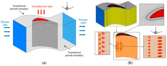
Figure 1.
Cascade Model of Numerical Simulation. (a) Heat-transfer mode. (b) Mesh.
The structural component is fabricated from a user-defined 2Cr13 alloy, which has a mass density of 7750 kg/m3 and a specific heat capacity of 450 J/(kg·K). Air serves as the working fluid, where its density, specific heat capacity, and thermal conductivity are provided through interpolation functions, and dynamic viscosity is derived using Sutherland’s law. The computational mesh was created in Fluent Meshing, with the grid layout illustrated in Figure 1b [37]. Boundary layers were incorporated on the blade surface, coolant plenum walls, and the interior channels of the film cooling holes. An initial boundary layer thickness of 0.003 mm was applied, accompanied by a growth rate of 1.2. Respectively, 18, 16, and 18 boundary layers were assigned to these regions. Mesh refinement was also conducted around these areas to maintain y+ values near 1.
2.2. Boundary Conditions and Computational Procedures
Boundary conditions for both the primary and secondary flow domains were defined according to experimental operating conditions. A pressure inlet condition was applied at the mainstream inlet, with pressures set to 110 kPa and 120 kPa, corresponding to two distinct operational points measured in the stabilized section of the wind tunnel. The inlet temperature was assigned based on thermocouple readings from the same location. The outlet was defined as an atmospheric pressure boundary. For the secondary flow, a mass flow inlet condition was used, and the temperature was assigned according to the measured coolant outlet temperature during testing. Turbulence parameters were consistent with the experimental setup: 1% for the mainstream and 2% for the secondary flow. The side walls in the y-direction of the mainstream domain were configured as translationally periodic boundaries. The blade was modeled entirely as a solid domain featuring a thermal conductivity of 22.2 W/(m·K). At the fluid-solid interface, a conjugate heat transfer condition was imposed, satisfying the following requirements:
where T represents the temperature at the computational interface, k is the thermal conductivity, and the subscripts “fluid” and “vane” refer to the fluid region and the solid blade, respectively. The symbol n indicates the Z-axis.
Numerical simulations were carried out in Fluent 2021R2. A pressure-based solver was utilized to resolve the RANS equations. The SIMPLEC algorithm handled the pressure–velocity coupling. The gradient term was discretized with the cell-based least-squares method. The central-difference approach was used to discretize the diffusion term, while a second-order upwind approach was applied to discretize the convection term. Thus, the numerical solution attains second-order accuracy. Numerical simulations were conducted using mesh sizes of 7 million, 9 million, 11 million, and 12 million cells, as shown in Figure 2. When refined to 11 million cells, the temperature along the blade midline stabilized and showed no further changes. Consequently, this study utilizes a mesh size of 11 million cells. In the present computations, convergence is assumed when all residuals drop below 10−5 and become stable. Convergence is also confirmed when the mass flow rates at the inlet and outlet remain unchanged with further iterations.
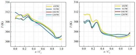
Figure 2.
The centerline temperature of vane with different grid numbers.
2.3. Experimental Blade Model and Pressure–Temperature Measurement System
Figure 3 shows the experimental cascade. The cascade contains five blades and two endwall covers, forming four flow passages. In the aerodynamic test, only the central blade is equipped with pressure taps; the other blades have no taps. In the heat-transfer test, the middle three blades have identical film cooling holes, whereas the upper and lower blades have no holes. This layout enhances the periodicity of the measured data. The endwall covers are made of aerospace-grade glass. Each blade is located on the cover by alignment pins. Six secondary-air channels are machined in the cover to supply coolant to three blades and to generate a cooling film. Sixteen pressure taps are installed at both the inlet and the outlet of the cascade. These taps measure the inlet and outlet Mach numbers and verify the periodicity of the flow field.
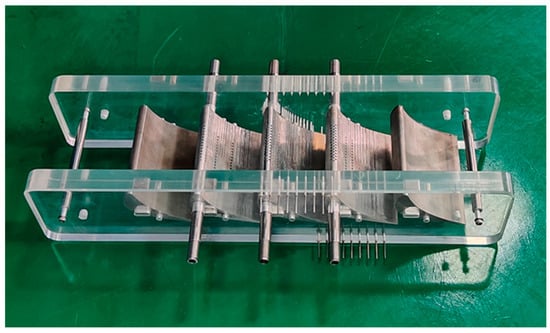
Figure 3.
Test Cascade Model.
Figure 4 [37] shows the blade models with varying film-hole configurations. The Base scheme reproduces the original distribution of cooling holes on the blade. Hole pattern #1 arranges the holes along the 25 K isotherm. Hole pattern #2 arranges the holes along the 50 K isotherm. Four model sets are prepared for the experiments. One set has no film cooling holes; it serves to investigate the blade’s aerodynamic properties. The other three sets contain the above cooling-hole layouts; they are utilized to assess film cooling effectiveness.
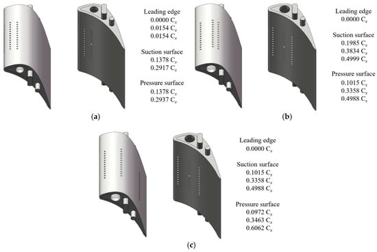
Figure 4.
The Film Hole Arrangement. (a) Base, (b) Hole pattern #1, (c) Hole pattern #2.
The aerodynamic model carries 32 pressure taps on the surface. Distribution of surface pressure is recorded using an electronic pressure-scanning valve. For the heat-transfer model, K-type sheathed thermocouples are installed. Each thermocouple is embedded in a shallow groove and fixed with adhesive. The blade surface is polished afterward to keep a smooth profile and to reduce installation interference. A temperature acquisition unit measures the junction temperature of every thermocouple. Both pressure taps and thermocouple junctions are located at the mid-span section. The measured data therefore represent the flow and heat-transfer characteristics along the centerline of the turbine vane.
2.4. Wind Tunnel and Experimental Setup
The study was conducted in a blow-down, downward-blowing, transonic planar cascade wind tunnel. The wind-tunnel facility included a storage-air system, a control system, a main duct, and a test section. Figure 5 shows the schematic layout of the entire experimental system. The upper and lower inlet-duct walls of the mainstream in the test section positioned at a significant distance from the test blade. The distance from the outermost film hole to the blade side cover plate in the spanwise direction measures 28 mm. Hence, boundary layers developing along the sidewalls remain distant from the blade’s instrumented region, and the mainstream inlet boundary layer has a negligible effect on the test blade. A dedicated secondary flow system delivers the coolant air. A key aspect of the cooling effectiveness tests involves creating a thermal gradient between the mainstream and the secondary flows. Herein, the secondary flow is electrically elevated above the temperature of the mainstream. This inverse thermal strategy creates the necessary temperature gradient for heat transfer measurements.
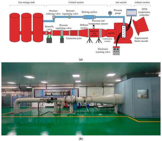
Figure 5.
The Experiment System. (a) Schematic diagram. (b) Photograph.
Figure 6 illustrates the secondary-flow supply system. Compressed air is initially drawn from a high-pressure storage tank. A pressure-reducing valve lowers the pressure to below 0.6 MPa. The gas then enters the heater. The airflow subsequently enters a 25 kW electric air heater. This unit is designed to heat the secondary flow to a target temperature of 573 K. A thermocouple positioned at the heater outlet continuously measures the gas temperature. A closed-loop control system employing a PID algorithm modulates the heater output to maintain the temperature within a narrow range of the target value. This system can deliver up to 200 m3/h of hot air to the heat-transfer model. At the beginning of each run, the secondary-flow system is started first and heats the model for one hour. When the model surface reaches the preset temperature and becomes stable, the wind tunnel is switched on and the test begins.
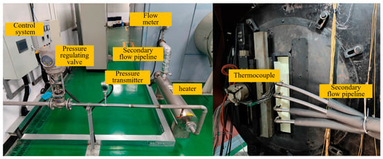
Figure 6.
The Secondary Flow System.
3. Uncertainty Analysis and Turbulence Model Validation
3.1. Uncertainty Analysis of Integrated Cooling Effectiveness
The heat-transfer blade in this experiment is subjected to cooling, both internal and external, and the metallic specimen experiences convective heat transfer and solid conduction, unlike the adiabatic boundary condition adopted in many studies. As a result, the adiabatic film cooling effectiveness η = (T∞ − Tw)/(T∞ − Tc) cannot describe the cooling effectiveness here. Therefore, our team proposes an integrated cooling effectiveness, defined as:
As per the equation for error propagation,
Therefore, the uncertainty of the integrated cooling effectiveness is:
The primary sources of error in the overall cooling effectiveness measurements are the mainstream, film-hole exit, and wall temperatures. Throughout this study, all temperatures are acquired with thermocouples, whose systematic error is 1%. Under the reference test condition, the secondary-flow system is first set to the upper limit Tc = 150 °C; the measured values are Tm = 29 °C, Tc,outlet = 138 °C, Twall = 96 °C. When the system is adjusted to the lower limit Tc = 60 °C, the readings change to Tm = 32 °C, Tc,outlet = 56 °C, Twall = 46 °C. Accordingly, the uncertainties surrounding the overall cooling effectiveness are 2.04% for ϕ Tc=150 °C = 0.61 and 5.42% for ϕ Tc=150 °C = 0.58.
In addition, a concise overview of the essential experimental parameters and their associated uncertainties is presented in the Table 1.

Table 1.
Summary of Key Experimental Parameters and Uncertainties.
3.2. Turbulence Model Validation for Heat Transfer and Aerodynamic Performance
The turbulence model was validated with the test data. Boundary conditions were configured with a mainstream inlet total pressure of 0.11 MPa and a temperature of 298.2 K, while the outlet total pressure was maintained at one atmosphere. The secondary-flow temperature was 363 K, and its mass-flow ratio was 2.08%. As shown in Figure 7 [37], which compares experimental and simulation results using the dimensionless axial coordinate, the SST k-ω model gives the closest agreement with the measurements on both suction and pressure sides. On the blade suction side, the deviation in overall cooling effectiveness remains below 4%. Hence, the SST k-ω model was selected for all subsequent numerical simulations in this study.
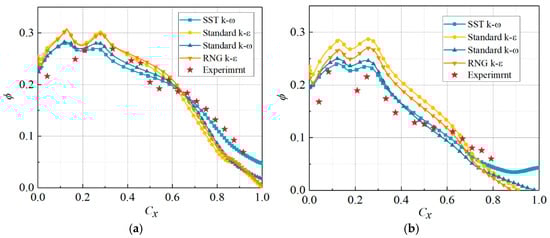
Figure 7.
Distribution of Overall cooling effectiveness of Vanes with Various Turbulence Models. (a) SS, (b) PS.
Turbulence model validation was performed for the aerodynamic performance of the turbine vane. The mesh settings were kept identical to those of the heat-transfer model. The mainstream inlet total pressure was 111 kPa. The inlet temperature was 297.36 K. The outlet static pressure was 100.8 kPa. Figure 8 shows the blade-surface pressure and Mach-number distributions predicted by different turbulence models. The y-axis gives the ratio of blade-surface pressure to mainstream total pressure. For both surface pressure and Mach number, all turbulence models agree well with the experimental data. On the pressure side, the discrepancy between simulation and experiment is less than 0.9%, indicating excellent predictive capability. On the suction side, the models predict different extents of the flow-separation region. The SST k-ω model yields the closest match to the measurements. Therefore, the SST k-ω model was adopted for the aerodynamic numerical simulation of the turbine vane.
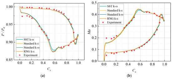
Figure 8.
Aerodynamic Outcome of Vane Utilizing Various Turbulence Models. (a) Surface pressure distribution. (b) Surface Mach number distribution.
4. Results and Discussion
4.1. Analysis of Aerodynamic Performance of Turbine Vanes
Figure 9 shows the pressure and Mach number distributions on the blade surface under different turbine expansion ratios. Boosting the turbine expansion ratio alleviates the pressure exerted on the blade surface while simultaneously raising the Mach number. The pressure on the front part of the blade is less sensitive to variations in the turbine expansion ratio, while the pressure on the rear part of the blade changes more significantly with an increasing expansion ratio. Compared to the pressure side, variations in the turbine expansion ratio exert a greater impact on the suction side. When the expansion ratio is small (π < 1.4), an increase in the expansion ratio significantly raises the Mach number on the blade surface. However, when the expansion ratio exceeds 1.4, the flow velocity inside the blade passage becomes higher, the compressibility of the air increases, and the rear part of the blade passage gradually approaches choking. At this point, additional enhancements in the expansion ratio lead to smaller changes in the Mach number. Beginning from the forefront of the blade, there is a sudden surge in the near-wall fluid velocity on both the pressure side and the suction side. When the mainstream fluid reaches the leading edge, it directly impacts the stagnation point and comes to rest. Subsequently, due to the impact of the pressure differential, the velocity increases sharply. Before 0.6 Cx, the near-wall velocity on the suction side of the blade gradually increases due to the expansion and contraction of the flow passage, but the growth rate remains relatively constant. After 0.6 Cx, the rapid expansion of the flow passage causes the pressure on the suction side to rise, leading to a corresponding decrease in the Mach number. On the front half of the blade, the velocity on the pressure side changes little. In the rear half, due to the rapid expansion of the flow passage, the velocity on the pressure side increases rapidly.
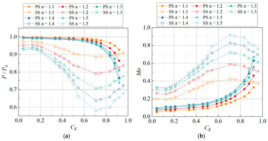
Figure 9.
The Surface Pressure and Mach Number Distribution under Different Turbine Expansion Ratios. (a) Relative pressure, (b) Mach number.
4.2. Exploring Variations in Cooling Effectiveness with Various Film Hole Configurations
The blowing ratio M = (ρc·vc)/(ρm·vm) a key metric for evaluating coolant usage efficiency. When considering systems with multiple rows of film holes, it becomes essential to account for the varying mainstream velocities adjacent to each row. To analyze the results more accurately, a local blowing ratio, Mlocal, is defined. Mlocal is formulated as the multiplication of the density ratio between the mainstream and coolant flows and the speed ratio between the mainstream and coolant flows at the exit section of the film holes, expressed as:
where ρ and v denote the density and velocity of the corresponding fluids, respectively.
The integrated cooling effectiveness along the flow direction is averaged in the x-direction to obtain the streamwise-averaged integrated cooling effectiveness, reflecting the overall efficiency of film cooling. Its mathematical expression is:
Figure 10, Figure 11 and Figure 12 compare the blade integrated cooling effectiveness at a secondary-flow temperature of 363 K and at different mass-flow ratios. The secondary-flow volume rates are measured at 48, 72 and 192 m3/h, equating to mass flow ratios of 2.08%, 3.11% and 8.30%, respectively. At a small mass-flow ratio, in the front part of the blade (Cx < 0.2), the Base case shows higher integrated cooling effectiveness on both the suction and pressure sides than the optimized film-hole layouts. When Cx > 0.35, the trend reverses. On the suction side, the CEs of Hole pattern #1 and #2 differ little in the range 0.3 Cx to 0.76 Cx. However, in the vicinity of the front and rear edges of the blade, the integrated cooling effectiveness of #2 exceeds that of #1.
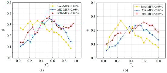
Figure 10.
Comparison of the Overall cooling effectiveness of Vanes with Various Film Hole Layouts at an MFR of 2.08%. (a) SS, (b) PS.
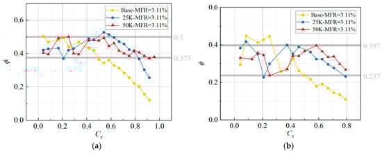
Figure 11.
Comparison of the Overall cooling effectiveness of Vanes with Various Film Hole Layouts at an MFR of 3.11%. (a) SS, (b) PS.
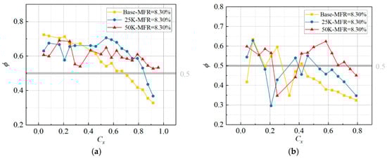
Figure 12.
Comparison of the Overall cooling effectiveness of Vanes with Various Film Hole Layouts at an MFR of 8.30%. (a) SS, (b) PS.
When the mass flow rate of the secondary stream rises, the integrated cooling effectiveness of the Base case decays faster in the downstream direction. For Cx > 0.4, Hole pattern #1 and #2 both outperform Base on the suction side and the pressure side. The coolant film of Hole pattern #2 is more uniform on the suction side; therefore, its cooling effectiveness distribution is more even than the other two cases. As shown in Figure 11, the cooling effectiveness of Hole pattern #2 on the whole suction side stays between 0.375 and 0.5. On the pressure side, its cooling effectiveness ranges from 0.237 to 0.397, which is almost the same as #1. The minimum cooling effectiveness of Base is 0.1 at the blade trailing edge. Along each curve, the integrated cooling effectiveness rises sharply after every row of film holes and then decays, with this pattern being particularly prominent on the pressure side.
In a real gas turbine, 15% of the total compressor discharge is bled for turbine cooling. About 10% of the total flow cools the high-pressure turbine, and most of that air cools the blades. When the turbine inlet temperature is 1544 K and the coolant temperature is 773 K, take the adiabatic effectiveness ϕ = 0.5 as a cooling-performance criterion. At this level, film cooling lowers the blade temperature by 385.5 K. Figure 13 shows the contour map of comprehensive cooling efficiency distribution for blades with different film cooling hole configurations. In Figure 11 and Figure 12, using 0.5 as the boundary, the cooling efficiency of the entire suction surface for Hole pattern #2 is above the boundary line. Base and #1 have 31.02% and 15.28% of their areas below the line, respectively. On the pressure side, Base exceeds 0.5 only in the range 0.057 < Cx < 0.284, which covers 22.7% of the surface. Hole pattern #1 has three regions where the cooling efficiency is above 0.5, specifically at Cx < 0.155, 0.329 < Cx < 0.395, and 0.436 < Cx < 0.522, covering 30.7% of the blade’s pressure surface area. Hole pattern #2 satisfies ϕ > 0.5 at Cx < 0.222 and 0.393 < Cx < 0.733, covering 56.2% of the surface. Therefore, at MFR = 8.3%, Hole pattern #2 meets the desired cooling level (ϕ = 0.5) over 78.1% of the whole blade area, which is 1.35 times that of Hole pattern #1 (57.7%) and 1.71 times that of Base (45.8%).
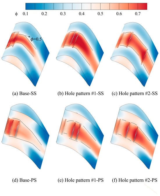
Figure 13.
Comprehensive cooling efficiency distribution contour map of blades with different film cooling hole configurations.
Figure 14, Figure 15 and Figure 16 present the surface pressure and Mach-number distributions for blades with three different film-hole layouts. Gray vertical lines mark the film holes on the leading edge and the suction side. Blue vertical lines mark the film holes on the pressure side. The first row of leading-edge holes is identical in the three layouts. Different blowing ratios, however, give different cooling effectiveness at the leading edge. Heat transfer in the test is coupled; it includes convective heat transfer and thermal convection. The second and third rows of leading-edge holes in the Base case also contribute to cooling the front section of the blade. Near the leading edge on the suction side, the Base case shows very high cooling effectiveness. Three rows of holes are arranged there; this configuration is known as “showerhead cooling”. It greatly improves cooling on the suction-side leading edge but sharply reduces cooling near the trailing edge. Moreover, although “showerhead cooling” raises the effectiveness near the suction-side leading edge, it does not enhance cooling near the pressure-side leading edge.
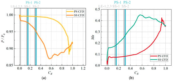
Figure 14.
The Distribution of Vane Surface Pressure and Ma of Base under P0 = 0.11 MPa. (a) Pressure, (b) Ma.
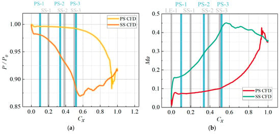
Figure 15.
The Distribution of Vane Surface Pressure and Ma of Hole Pattern #1 under P0 = 0.11 MPa. (a) Pressure, (b) Ma.
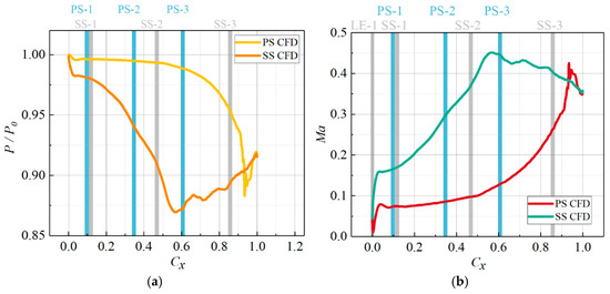
Figure 16.
The Distribution of Vane Surface Pressure and Ma of Hole Pattern #2 under P0 = 0.11 MPa. (a) Pressure, (b) Ma.
Table 2 lists the local blowing ratios of the respective rows of film holes at MFR = 4.15% for the three layouts. The local blowing ratio plays a crucial role in the performance of film cooling. In the Base case, the film holes are concentrated near the leading edge of the blade, where the mainstream velocity is lower, resulting in high local blowing ratios for LE-1, LE-3, PS-1, and PS-2, which in turn reduces the cooling effectiveness. Hole pattern #1 and Hole pattern #2 distribute the holes more evenly across the blade surface compared to the Base case, compensating for the limited coverage along the streamwise direction of a single row of holes. Moreover, the local blowing ratios at the corresponding positions in patterns #1 and #2 are lower than those in the Base case, leading to better attachment of coolant jets to the surface and thereby enhancing film cooling effectiveness. Typically, the trailing edge is considered a vulnerable area for film cooling. The third-row holes of the two optimized layouts exhibit almost identical local blowing ratios. In Hole pattern #1, the third row is positioned more than 0.5 Cx upstream of the trailing edge on both the suction and pressure sides. In contrast, for Hole pattern #2, the third row is only 0.1427 Cx upstream on the suction side and 0.3938 Cx upstream on the pressure side. This placement provides a strong supplement to the trailing-edge film cooling.
Table 2.
The local blowing ratio of MFR = 4.15%.
4.3. Flow-Field Analysis and Mechanism Exploration Based on Simulation Results
Figure 17, Figure 18 and Figure 19 sample five streamwise stations on the blade for each hole layout and plot the spatial distribution of sectional overall cooling effectiveness. For the conventional layout, the film issued at station P1 separates strongly. Most coolant remains above the suction side. There is hardly any coolant trace close to the leading edge of the pressure side. The Base case places three rows of film holes upstream of P1. A large part of the coolant still stays above the suction side, yet the remaining coolant attaches to the blade surface and provides reasonable wall protection. By contrast, in Hole pattern #1 and Hole pattern #2 the coolant at P1 stays closer to the surface. Pattern #1 forms a more uniform film, whereas pattern #2 attains higher effectiveness. However, both layouts have only one row of holes upstream of P1, so the coolant flow rate is low and the leading-edge cooling capability is limited.
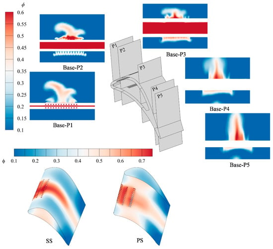
Figure 17.
Distribution of cooling effectiveness across Base Surface and Flow Section.
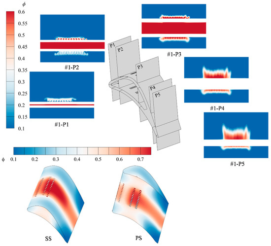
Figure 18.
Distribution of cooling effectiveness across Hole Pattern #1 Surface and Flow Section.
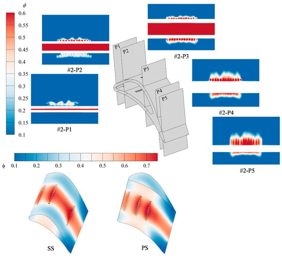
Figure 19.
Distribution of cooling effectiveness across Hole Pattern #2 Surface and Flow Section.
At station P2, a consistent cooling film can be observed on the pressure side. The film forms because the jets issued from the leading-edge holes oppose the flow of the main stream; the vortex structures generated by their interaction entrain the coolant and lift part of it off the surface of the blade. Under the local pressure gradient on the pressure side the lifted film separates and then re-attaches. Upstream of P2 every layout has three rows of film holes. The last two are closest to P2 in Hole pattern #1, farther in Hole pattern #2, and farthest in the Base case. On the suction side, patterns #1 and #2 create distinct jet columns, and the mixed mainstream–secondary flow between the columns joins them tightly. In the Base case the coolant accumulates near the mid-span region of the suction side when it reaches P2, so the cooling effectiveness there is very high. On the pressure side the Base jets do not merge well; uncooled gaps remain between adjacent columns. These gaps are much smaller in patterns #1 and #2.
When the coolant jets develop to P3, every hole layout builds a high-effectiveness film on the suction side. The spanwise coverage is not the same; the Base case covers a narrower width than Hole pattern #1 and Hole pattern #2. On the pressure side the Base case forms a continuous film, but its effectiveness falls short in comparison to Hole pattern #1 and Hole pattern #2. As the jets continue to evolve and reach P4 and P5, the Base film grows in the direction normal to the wall, so its height increases but its spanwise coverage shrinks. The zones of high effectiveness are limited to the few central holes, which is unfavorable for film cooling. For Hole pattern #1 and Hole pattern #2 the film height also rises, yet the loss in spanwise coverage is minor. In particular, Hole pattern #2 still keeps a high effectiveness when the film reaches P4 and P5.
The three layouts employ the same cooling cavity geometry. All film holes of Base lie upstream of 0.3 Cx. All film holes of Hole pattern #1 lie upstream of 0.5 Cx. The film holes of Hole pattern #2 extend from the leading edge to 0.85 Cx. This specific hole configuration at pattern #2 contributes to enhancing ineffective cooling towards the end of the surface through two main mechanisms. (1) External film cooling. The third row of holes on both sides (suction and pressure side) is close to the trailing edge, so the jets from these rows suffer the least decay before they reach the trailing edge. (2) Internal convection. The same third-row holes intensify coolant flow in the vicinity of the trailing edge, which raises the convective heat transfer inside the cooling cavity and within the holes. This effect provides an important supplement to the trailing-edge film cooling.
Figure 20 displays the spatial distribution of x-vorticity at the five streamwise stations. A massive horseshoe-shaped vortex appears in Figure 20a. After the Base leading-edge jet issues, part of the coolant detaches from the blade surface due to entrainment by the horseshoe vortex. The fluid entrained by the horseshoe vortex is higher in temperature and tends to invade the base of the cooling jet. By comparing the film-effectiveness contours at different cross-sections, we find that spanwise jet-induced vortex pairs with alternating sign give better spanwise film continuity. For instance, on the suction side at P1 in Figure 20a,c the above vortex pattern is weak, and the produced film shows poor continuity. At positions P1, P2, and P3, the maximum vorticity reaches approximately ±7000 s−1. The Base configuration exhibits the widest distribution of high vorticity regions and the longest characteristic length in the z-direction. Vortices in Hole pattern #1 and Hole pattern #2 are better attached to the wall, with high vorticity regions showing alternating positive and negative distributions near the film holes. At P4 and P5, vortex strength weakens, and the maximum vorticity decreases to about ±6000 s−1. In the Base case, the high vorticity region becomes smaller and exhibits alternating patterns, whereas Hole pattern #1 shows the smallest vorticity values and distribution range. Higher vorticity makes the jet column more distinct. For Hole pattern #1 the vortex structures decay at P4 and P5, and the jet columns are not observed there. On the suction side of the Base case four counter-rotating vortex pairs exist at P4 and P5; they lift the coolant strongly in the wall-normal direction and reduce its spanwise coverage. Changing the hole positions alters the local static pressure in the hole-row region, which influences the flow in the cooling cavity. Variations in vortex patterns near the hole exits, caused by the internal and external flow interaction, directly impact the film cooling effectiveness.
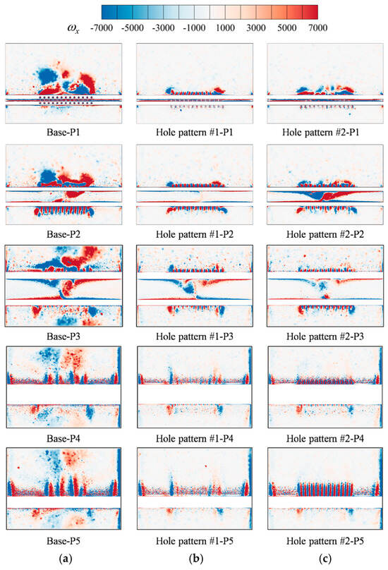
Figure 20.
Spatial Distribution of x-vorticity in Different Streamwise Sections. (a) Base, (b) Hole pattern #1, (c) Hole pattern #2.
5. Conclusions
This paper proposes a film cooling-hole arrangement along conjugate isotherms. First, cascade wind-tunnel tests were carried out to evaluate blade aerodynamics at different turbine expansion ratios. Second, the performance of film holes optimized along various temperature gradients was compared with that of a conventional layout. Finally, a CFD study was conducted to explore the flow-field structures and the mechanism behind the optimization when holes follow the conjugate isotherms. The principal discoveries can be summarized as follows:
- (1)
- An increase in turbine expansion ratio lowers the blade-surface static pressure and raises the local Mach number. The pressure on the front half of the blade is insensitive to the expansion-ratio change, whereas the rear half shows a much sharper pressure variation. The suction side experiences a greater impact from changes in the expansion ratio compared to the pressure side.
- (2)
- At a relatively low mass-flow rate, the “showerhead cooling” of Base greatly enhanced the cooling effectiveness along the leading edge on the suction side, but it also markedly reduced the trailing-edge cooling. The film holes in Hole pattern #1 and Hole pattern #2 were distributed more uniformly over the blade. This layout offset the limited streamwise coverage of a single-row film. The suction side showed a rising trailing-edge cooling effectiveness for Hole pattern #2, 83.04% higher than Base and 29.18% higher than Hole pattern #1. On the pressure side, the enhancements were 17.71% and 55.03%, respectively.
- (3)
- For both aerodynamic and heat transfer applications, numerical computation reliably predicted the experimentally measured trends of blade-surface pressure distribution and overall cooling effectiveness. The aerodynamic prediction error was within 3.81%. The heat-transfer prediction error was within 8.3%.
- (4)
- Changing the film-hole arrangement modified the flow inside the coolant cavity. Distinct vortex patterns formed near film hole exits as a result of the internal flow interacting with the external flow, consequently influencing the film cooling effectiveness. On the suction side, the conventional layout produced a high-effectiveness region mainly at the leading edge and its vicinity. For Hole pattern #1, the high-effectiveness region was primarily in the middle part of the blade. Pattern #2 displayed a more uniform cooling effectiveness distribution on the blade surface compared to Pattern #1, as there was no clearly defined high-effectiveness zone. Even though both patterns featured a single row of film holes at the leading edge, Pattern #2 offered superior leading-edge cooling effectiveness.
Author Contributions
Conceptualization, C.L. and Y.L.; Methodology, Y.J. and Y.L.; Software, Z.S.; Validation, Y.J.; Resources, C.L. and G.X.; Data curation, Z.S.; Writing—original draft, Z.S.; Writing—review & editing, Y.J. and Y.L.; Visualization, X.H.; Project administration, X.H. and G.X.; Funding acquisition, C.L., X.H. and G.X. All authors have read and agreed to the published version of the manuscript.
Funding
This research was funded by the Basic Research for National Science and Technology Major Project of China (Yongbao Liu: Grant No. J2019-I-0012), the Key Project of Logistics Research (Xing He: Grant No. BHJ22J014).
Data Availability Statement
The data presented in this study are available on request from the corresponding author due to privacy, legal, or ethical reasons.
Conflicts of Interest
The authors declare no conflict of interest.
References
- Zhang, J.; Zhang, S. Recent advances in film cooling enhancement: A review. Chin. J. Aeronaut. 2020, 33, 1119–1136. [Google Scholar] [CrossRef]
- Zakaria, M. Unsteady simulation of flow and heat transfer in a transonic turbine stage under non-uniform inlet conditions. Int. Commun. Heat Mass Transf. 2021, 129, 105660. [Google Scholar] [CrossRef]
- Wang, B.; Wang, F.; Zhang, X.; Wang, J.; Xue, T. Numerical analysis of cooling efficiency for turboshaft engines with converging-diverging film cooling holes. Int. J. Therm. Sci. 2023, 185, 108044. [Google Scholar] [CrossRef]
- Zhang, W.; Zeng, R.; Jing, L.; Liu, S.; Haiyong, C.; Li, G. Investigation of cooling performance degradation of impingement/effusion structure on pressure side of nozzle guide vane. Case Stud. Therm. Eng. 2022, 33, 101991. [Google Scholar] [CrossRef]
- Li, G.; Wan, L. Film cooling improvement of dovetail hole compared to cylindrical hole at different hole row locations on nozzle guide vane. Case Stud. Therm. Eng. 2023, 45, 103015. [Google Scholar] [CrossRef]
- Goldstein, R.J.; Eckert, E.R.G.; Ramsey, J.W. Film cooling with injection through holes: Adiabatic wall temperatures downstream of a circular hole. J. Eng. Gas Turbines Power 1968, 90, 384–393. [Google Scholar] [CrossRef]
- Gritsch, M.; Colban, W.; Schär, H.; Döbbeling, K. Effect of hole geometry on the thermal performance of fan-shaped film cooling holes. J. Turbomach. 2005, 127, 718–725. [Google Scholar] [CrossRef]
- Jia, Y.; Liu, Y.; Meng, Z.; He, X.; Liu, Y. The film cooling performance of spiral-channel holes on turbine guide vane. Case Stud. Therm. Eng. 2023, 53, 103846. [Google Scholar] [CrossRef]
- Jackson, D.J.; Lee, K.L.; Ligrani, P.M.; Johnson, P.D. Transonic aerodynamic losses due to turbine airfoil, suction surface film cooling. J. Turbomach. 2000, 122, 317–326. [Google Scholar] [CrossRef]
- Zhang, G.; Liu, J.; Sundén, B.; Xie, G. Comparative study on the adiabatic film cooling performances with elliptical or super-elliptical holes of various length-to-width ratios. Int. J. Therm. Sci. 2020, 153, 106360. [Google Scholar] [CrossRef]
- Yusop, N.M.; Ali, A.H.; Abdullah, M.Z. Computational study of a new scheme for a film-cooling hole on convex surface of turbine blades. Int. Commun. Heat Mass Transf. 2013, 43, 90–99. [Google Scholar] [CrossRef]
- Sargison, J.E.; Oldfield, M.L.G.; Guo, S.M.; Lock, G.D.; Rawlinson, A.J. Flow visualisation of the external flow from a converging slot-hole film-cooling geometry. Exp. Fluids 2005, 38, 304–318. [Google Scholar] [CrossRef]
- Okita, Y.; Nishiura, M. Film effectiveness performance of an arrowhead-shaped film-cooling hole geometry. J. Turbomach. 2007, 129, 331–339. [Google Scholar] [CrossRef]
- Huang, Y.; Zhang, J.Z.; Wang, C.H. Shape-optimization of round-to-slot holes for improving film cooling effectiveness on a flat surface. Heat Mass Transf. Waerme Stoffuebertragung 2018, 54, 1741–1754. [Google Scholar] [CrossRef]
- Zhu, X.D.; Zhang, J.Z.; Tan, X.M. Numerical assessment of round-to-slot film cooling performances on a turbine blade under engine representative conditions. Int. Commun. Heat Mass Transf. 2019, 100, 98–100. [Google Scholar] [CrossRef]
- Sargison, J.E.; Guo, S.M.; Oldfield, M.L.G.; Lock, G.D.; Rawlinson, A.J. A converging slot-hole film-cooling geometry-Part 1: Low-speed flat-plate heat transfer and loss. J. Turbomach. 2002, 124, 453–460. [Google Scholar] [CrossRef]
- Dai, P.; Lin, F. Numerical study on film cooling effectiveness from shaped and crescent holes. Heat Mass Transf. Waerme Stoffuebertragung 2011, 47, 147–154. [Google Scholar] [CrossRef]
- Lu, Y. Effect of Hole Configurations on Film Cooling From Cylindrical Inclined Holes for the Application To Gas Turbine Blades. Ph.D. Thesis, Louisiana State University and Agricultural & Mechanical College, Baton Rouge, LA, USA, 2007. [Google Scholar]
- Bunker, R.S. Film cooling effectiveness due to discrete holes within a transverse surface slot. In Proceedings of the Turbo Expo 2002: Power for Land, Sea, and Air, Amsterdam, The Netherlands, 3–6 June 2002; American Society of Mechanical Engineers: New York, NY, USA; International Gas Turbine Institute: Houston, TX, USA, 2002. [Google Scholar]
- Zhang, B.L.; Zhu, H.R.; Liu, C.L.; Wei, J.-S. Experimental Study on the Film-Cooling Characteristics of the Cylindrical Holes Embedded in Sine-Wave Shaped Trench. J. Eng. Gas Turbines Power 2020, 142, 101003. [Google Scholar] [CrossRef]
- Na, S.; Shih, T.I.P. Increasing adiabatic film-cooling effectiveness by using an upstream ramp. J. Heat Transf. 2007, 129, 464–471. [Google Scholar] [CrossRef]
- Zhou, W.; Peng, D.; Wen, X.; Liu, Y.; Hu, H. Unsteady analysis of adiabatic film cooling effectiveness behind circular, shaped, and sand-dune-inspired film cooling holes: Measurement using fast-response pressure-sensitive paint. Int. J. Heat Mass Transf. 2018, 125, 1003–1016. [Google Scholar] [CrossRef]
- Benabed, M. Computational optimization of Coanda effect on film-cooling performance. J. Thermophys. Heat Transf. 2015, 29, 757–765. [Google Scholar] [CrossRef]
- Meng, Z.; Liu, Y.; Li, Y.; Yu, Y. A study on cooling performance of surface-modified TBC-film cooling system with bio-inspired micro-riblets. Int. J. Therm. Sci. 2022, 172, 107340. [Google Scholar] [CrossRef]
- Ou, S.; Rivir, R.B. Leading edge film cooling heat transfer with high free stream turbulence using a transient liquid crystal image method. Int. J. Heat Fluid Flow 2001, 22, 614–623. [Google Scholar] [CrossRef]
- Jiang, H.W.; Han, J.C. Effect of film hole row location on film effectiveness on a gas turbine blade. J. Heat Transf. 1996, 118, 327–333. [Google Scholar] [CrossRef]
- Liu, C.; Zhu, H.; Fu, Z.; Xu, R.-H. The effects of inlet Reynolds number, exit Mach number and incidence angle on leading edge film cooling effectiveness of a turbine blade in a linear transonic cascade. In Proceedings of the Turbo Expo: Power for Land, Sea, and Air, Montréal, QC, Canada, 15–19 June 2015; American Society of Mechanical Engineers: New York, NY, USA, 2015; Volume 56727, p. V05BT12A025. [Google Scholar]
- Zhang, L.; Moon, H.K. Turbine blade film cooling study: The effects of film hole location on the pressure side. In Proceedings of the Turbo Expo: Power for Land, Sea, and Air, Montréal, QC, Canada, 14–17 May 2007; Volume 47934, pp. 497–506. [Google Scholar]
- Mhetras, S.; Han, J.C.; Rudolph, R. Film-cooling effectiveness from shaped film cooling holes for a gas turbine blade. In Proceedings of the Turbo Expo: Power for Land, Sea, and Air, Berlin, Germany, 9–13 June 2008; Volume 43147, pp. 837–848. [Google Scholar]
- Mhetras, S.; Han, J.C.; Rudolph, R. Effect of flow parameter variations on full coverage film-cooling effectiveness for a gas turbine blade. J. Turbomach. 2011, 134, 93–103. [Google Scholar] [CrossRef]
- Liu, K.; Yang, S.F.; Han, J.C. Influence of coolant density on turbine blade film-cooling with axial and compound shaped holes. J. Heat Transf. 2014, 136, 044501. [Google Scholar] [CrossRef]
- Rallabandi, A.P.; Li, S.J.; Han, J.C. Unsteady wake and coolant density effects on turbine blade film cooling using pressure sensitive paint technique. J. Heat Transf. 2012, 134, 081701. [Google Scholar] [CrossRef]
- Narzary, D.P.; Liu, K.C.; Rallabandi, A.P.; Han, J.-C. Influence of coolant density on turbine blade film-cooling using pressure sensitive paint technique. J. Turbomach. 2011, 134, 031006. [Google Scholar] [CrossRef]
- Fu, Z.; Zhu, H.; Cheng, L.; Han, J.-C. Experimental Investigation on the Effect of Mainstream Turbulence on Full Coverage Film Cooling Effectiveness for a Turbine Guide Vane. J. Therm. Sci. 2019, 28, 145–157. [Google Scholar] [CrossRef]
- Li, W.; Li, X.; Ren, J.; Jiang, H. Experimental investigation of wall thickness and hole shape variation effects on full-coverage film cooling performance for a gas turbine vane. Appl. Therm. Eng. 2018, 144, 349–361. [Google Scholar] [CrossRef]
- Jia, Y.H.; Liu, Y.B.; Meng, Z.W.; Yin, W.; Hua, W. Numerical study on film cooling effectiveness from spiral-channel hole. Int. Commun. Heat Mass Transf. 2023, 143, 106716. [Google Scholar] [CrossRef]
- Yuhao, J.; Yongbao, L.; Xing, H.; Zewei, M.; Shuai, Z. Arrangement guideline of film holes along conjugate temperature difference in turbine guide vanes. Chin. J. Aeronaut. 2025, 38, 103400. [Google Scholar] [CrossRef]
Disclaimer/Publisher’s Note: The statements, opinions and data contained in all publications are solely those of the individual author(s) and contributor(s) and not of MDPI and/or the editor(s). MDPI and/or the editor(s) disclaim responsibility for any injury to people or property resulting from any ideas, methods, instructions or products referred to in the content. |
© 2025 by the authors. Licensee MDPI, Basel, Switzerland. This article is an open access article distributed under the terms and conditions of the Creative Commons Attribution (CC BY) license (https://creativecommons.org/licenses/by/4.0/).