Abstract
To enhance the waterproofing performance of segment bolt holes in shield tunnels and ensure they meet the synergistic waterproofing requirements of segment joint sealing systems, a novel sealing gasket installed at the joint interface of the segment bolt hole has been designed. Numerical analysis was employed for a parametric study of factors influencing the waterproofing performance of the new gasket. Additionally, experimental research was conducted to evaluate its waterproofing capabilities. The study’s findings indicate that the hardness, height, and width of the novel bolt hole waterproof gasket significantly influence both the closure compression force and waterproofing performance. In contrast, the inner diameter primarily affects the closure compression force with a minimal impact on waterproofing performance. Compared to traditional water-swellable gaskets used for segment bolt holes, the novel EPDM (Ethylene Propylene Diene Monomer) waterproof gasket is more effective in mitigating the effects of manufacturing defects. For double-gasket segment joint sealing systems where the waterproofing strength of the bolt hole is critical, the adoption of this novel bolt hole waterproof gasket can better satisfy the synergistic waterproofing requirements between the two sealing gaskets, thereby effectively improving the overall waterproofing capacity of the segment joint sealing system.
1. Introduction
In recent years, with the rapid development of urban underground space and cross-river/sea tunnel projects, the long-term performance of shield tunnels under high water pressure and complex geological conditions has garnered significant attention [1,2]. Existing research indicates that the vast majority of leakage failures in shield tunnels occur in localized areas such as segment joints and bolt holes [3]. Consequently, as critical weak points in shield tunnel waterproofing, leakage at these potential seepage pathways directly threatens structural durability and operational safety. As shield tunnel construction continues to advance towards larger cross-sections and higher water pressure environments, the waterproofing challenges faced by segment joints and bolt holes will only intensify. Therefore, research into optimizing and enhancing the performance of these weak links in shield tunnel waterproofing is imperative.
Xiao et al. [3] summarized the development process of shield tunnel segment joint waterproofing systems, categorizing them into three generations based on their characteristics, and elaborating on the structural features and main applicable scopes of each generation. Currently, domestic and international scholars have conducted extensive research on the waterproofing performance of shield tunnel segment joints.
Research focused on single-channel joint sealing gasket waterproofing systems is relatively mature, with a rich array of research methods including theoretical analysis [4], numerical simulation [5,6], model tests [7,8], and full-scale tests [6,9].
Through these studies, the influence of factors such as cross-sectional structural features, joint deformation, and material composition on the waterproofing performance of single-channel sealing gaskets has been well-revealed [10,11,12]. The corresponding leakage mechanisms have been elucidated, and design schemes for selecting sealing gaskets based on contact stress as an evaluation index have been proposed [8,13].
On the other hand, with the increasing number of large-diameter underwater shield tunnels, the external water and soil pressure on segment linings continues to rise. The increased segment thickness also offers more options for joint waterproofing systems. To further enhance joint waterproofing performance and safety reserves, an increasing number of large-diameter underwater shield tunnels are adopting double-channel sealing gasket waterproofing systems [14,15,16]. Compared to single-channel sealing gaskets, the leakage mechanism and performance degradation of double-channel sealing gasket systems are more complex. Li et al. [17] validated the waterproofing advantages of double-channel sealing gaskets under high water pressure by comparing the failure modes of different waterproofing systems. Zhang et al. [5] clarified the principle behind the improved waterproofing capability of double-channel sealing gasket systems compared to traditional single-channel ones, by conducting dynamic fluid–structure interaction analysis on the waterproofing performance changes of double-channel sealing gaskets under external water pressure. Studies by various scholars on the enhanced waterproofing performance of double-channel sealing gaskets have shown that using them can improve the overall joint waterproofing performance by 10% to 20% compared to single-channel sealing gaskets [15,18]. Furthermore, when segment joints experience opening or misaligned deformation, double-channel sealing gasket waterproofing systems offer greater waterproofing reserves under the same conditions [19].
Overall, significant achievements have been made in researching single and double-channel sealing gasket waterproofing systems for shield tunnel segment joints. However, research on the waterproof performance of segment bolt holes remains very limited. For segment joints that utilize an outer single-channel sealing gasket + inner water-swellable rubber strip or inner and outer double-channel sealing gasket configurations, once the outer waterproofing is breached, the bolt holes directly become potential seepage pathways, significantly impacting the synergistic interaction mechanism of each waterproofing barrier within the overall segment joint waterproofing system. Currently, small-sized water-swellable rubber rings are mainly used as waterproofing measures for bolt holes. Compared to other waterproofing arrangements within the overall segment joint waterproofing system, their waterproofing performance is inferior [20], making them more prone to becoming the ultimate leakage channel, thereby leading to a decrease in the overall waterproofing performance of the segment joint. Additionally, traditional bolt hole water-swellable rubber gaskets are more severely affected by manufacturing defects, which can lead to uncontrolled or uneven expansion, resulting in localized insufficient waterproofing performance and further increasing the risk of leakage at the bolt hole locations. Therefore, it is necessary to thoroughly investigate methods to improve the waterproofing performance of bolt holes to ensure the overall waterproofing capability of segment joints.
Addressing the aforementioned issues, this paper proposes a novel Sealing gasket for segment bolt holes designed to be installed at the joint surface. Numerical simulation methods were employed to conduct parameterized analysis and optimization research on the waterproofing performance of this sealing gasket, thereby determining the most reasonable geometric dimensions. Furthermore, the effectiveness of the novel bolt hole Sealing gasket in enhancing waterproofing performance was validated using a self-developed bolt hole waterproofing performance test device.
2. Project Overview
The Shenzhen Pearl River Estuary Tunnel, located in Guangdong, spans 13,690 m. Its Humen-side shield section is 3590 m long, reaching a maximum buried depth of 115 m and encountering a maximum water pressure of 1.06 MPa. The tunnel primarily passes through 300 m of alluvium (composed mainly of silt, sand layers, and completely weathered gravelly sandstone), 450 m of “soft upper, hard lower” strata (weakly to slightly weathered gravelly sandstone), 930 m of weakly to slightly weathered granite rock strata (including fault fracture zones and weathering troughs), and 1820 m of weakly to slightly weathered gravelly sandstone. The shield tunnel lining segments feature an outer diameter of 12.9 m, an inner diameter of 11.7 m, a thickness of 0.6 m, and a width of 2 m, making it a large-diameter shield tunnel. The lining structure employs a “6 + 2 + 1” block division method with staggered joint assembly. The crown, adjoiner, and standard blocks all have a central angle of 40°. The concrete strength of the lining segments for this project is C60, and M36 inclined bolts of strength class 8.8 are used. The segment joints are designed with a double-sealed gasket system.
3. Design of a Novel Sealing Gasket for Segment Bolt Holes
To address the inadequate waterproofing performance of traditional water-swellable rubber rings used in bolt holes, a novel water-stop gasket is proposed to be installed at the bolt hole locations on the segment joint side. The novel bolt hole Sealing gasket is shown in Figure 1 and Figure 2, with its corresponding installation configuration shown in Figure 3. Its operational principle is similar to that of EPDM (ethylene propylene diene monomer) sealing gaskets: it resists external water pressure through the compressive force generated during the segment assembly process.
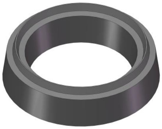
Figure 1.
Bolt hole sealing gasket.
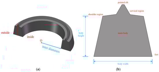
Figure 2.
Design parameter description of sealing gasket: (a) Sealing gasket Design Specification. (b) Sealing gasket Design Specification 2.
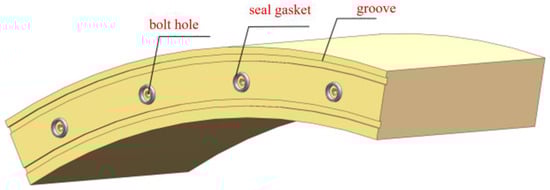
Figure 3.
Layout form of bolt hole sealing gasket.
When designing elastic gaskets for shield tunnel joints, there are two primary design criteria: the closure compression force design criterion and the most unfavorable condition waterproofing performance design criterion. The closure compression force criterion dictates that the compressive reaction force of the gasket, when compressed to its design height, must be less than the shield machine jacks’ ultimate jacking force. This is due to limitations imposed by both the shield machine jacks and the segment’s inherent strength. The most unfavorable condition waterproofing performance criterion specifies that under the most adverse joint deformation, the gasket’s short-term waterproofing capacity must not be less than the short-term waterproofing design index, and its long-term waterproofing capacity must not be less than the theoretical water pressure. Therefore, in the design of sealing gaskets for bolt holes, the main design basis similarly revolves around closure compression force and waterproofing performance under the most unfavorable conditions.
In this project, the opening when the gasket is fully assembled is 2 mm. The compressive reaction force of both the elastic gasket and the bolt hole sealing gasket, when compressed to the design height of 2 mm, should be less than the ultimate assembly force (100 kN/m) when the gasket is compressed to its design height. The design standard for the closure compression force of the sealing gasket can be calculated using Equation (1). Incorporating the actual project data, the design index for the closure compression force of the sealing gasket is 141.46 kN.
where K1 and K represent the compressive reaction force and the ultimate assembly force; L is the length of the gasket; FN is the design standard for the closure compression force of the sealing gasket; n is the number of bolt holes.
K1 + FN × n/L ≤ K
4. Numerical Simulation
This study utilizes the general-purpose finite element analysis software abaqus 6.14-4 to conduct an in-depth analysis of the compression performance and sealing mechanism of the novel gasket. This software is powerful in handling the nonlinear behavior of hyperelastic materials and complex contact problems, providing reliable numerical support for this research.
When analyzing the sealing gasket, we found a significant difference between two-dimensional (2D) and three-dimensional (3D) models during the compression process. As shown in Figure 4, the cross-section of the 2D model deforms uniformly around its axis of symmetry. However, in the 3D model, due to the combined effects of the material’s geometric characteristics and contact friction, the cross-sectional deformation tends to expand non-uniformly outwards.
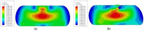
Figure 4.
Compression results of different sealing gasket models: (a) 2D Planar Model Compression Results. (b) Full 3D Model Compression Results.
Therefore, the sealing gasket cannot be simply equated to a 2D model for compression analysis. Considering the quarter symmetry of the sealing gasket in both radial and axial directions, this study utilizes a 1/4 three-dimensional finite element model for numerical simulation. Normal symmetric constraints are applied at the symmetric sections. The loading process is achieved by applying a precisely controlled downward displacement to the upper rigid plate to simulate the segment assembly and compression. The lower rigid plate is assigned a fully fixed boundary condition (as shown in Figure 5).
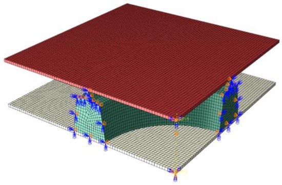
Figure 5.
Numerical simulation models of sealing gasket.
To accurately simulate the large deformation and nonlinear behavior of the sealing gasket, the gasket model uses eight-node linear hexahedral elements (C3D8R) with a hybrid formulation to prevent volumetric locking. The concrete segments, due to their much higher stiffness, are simplified as discrete rigid bodies in the model. To balance computational accuracy and efficiency, the model was meshed with refinement in critical contact zones of the gasket (such as the pointed rib and the feet) to precisely capture stress concentrations. Mesh independence has been verified through preliminary trial calculations.
The sealing gasket is made of EPDM rubber. As a hyper elastic material, EPDM’s non-linear stress–strain characteristics are typically represented by a strain energy density function. This paper selects the two-parameter Mooney-Rivlin constitutive model to characterize the material’s properties. The Mooney-Rivlin model effectively captures the non-linear response of EPDM within the range of moderate deformation, which facilitates subsequent analysis of the gasket’s potential leakage pathways and contact stresses. Its strain energy function is given by Equation (2), with specific material parameters detailed in Table 1. These parameters were obtained by conducting uniaxial compression tests on EPDM rubber materials of different hardness and then performing a nonlinear fit of the resulting stress–strain data in the ABAQUS software.

Table 1.
Hyper elastic constitutive parameters.
‘Face-to-face contact’ was established between the gasket and the upper and lower rigid plates, with self-contact also considered for the gasket’s outer surface. Normal behavior was defined as ‘hard’ contact, which allows for separation under tension but prevents penetration under compression. The tangential behavior used a penalty function-based friction model. Based on relevant research and engineering practice, the friction coefficient between the gasket and the concrete segment was set to 0.30, and the self-contact friction coefficient was set to 0.50. All operating conditions and their parameters are detailed in Table 2.
Table 2.
Optimization of working conditions for the structural form of Sealing gasket.
During the solution process, we set strict convergence criteria to ensure that the force and displacement residuals in all analysis steps were less than the solver’s default tolerance, thereby guaranteeing the accuracy and stability of the results. Furthermore, the validity and reliability of this numerical model will be verified by comparison with the indoor physical experiment results detailed in Section 6, specifically by directly comparing the simulated waterproofing performance of the optimal design with the experimental data.
where U is the strain potential energy; C10 and C01 are temperature-dependent material parameters; and I1 and I2 are the first and second strain invariants.
U = C10(I1 − 3) + C01(I2 − 3)
Based on the design requirements for the bolt hole sealing gasket, this study extracts the compression-closure force curve from the sealing gasket’s numerical model. The compression reaction force when the gasket is compressed to 2 mm is taken as the design index for the closure compression force. Like traditional elastic sealing gaskets that rely on physical compression to generate contact stress for waterproofing, the Novel sealing gasket also forms contact stress through physical compression against the segment, thereby effectively preventing water penetration.
However, there might be two potential leakage pathways between the sealing gasket and the segment: one at the upper part and another at the lower part (as shown in Figure 6). Therefore, when the gasket is compressed to 8 mm, the contact stress at both the upper and lower parts of the gasket are extracted, and their average value is used as the evaluation standard for waterproofing performance. This allows for a systematic analysis of the Novel sealing gasket’s waterproofing performance and design indices under the most unfavorable conditions.
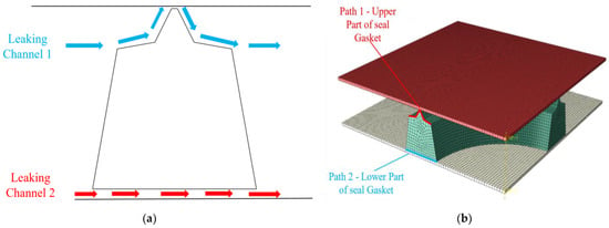
Figure 6.
Leakage channel and contact stress extraction path of sealing gasket: (a) Sealing gasket Leakage Paths. (b) Sealing gasket Contact Stress Extraction Paths.
5. Optimizing Sealing Gasket Parameters
5.1. The Influence of Hardness
Hardness is a crucial performance indicator for rubber materials, directly linked to their compression resistance and wear resistance. Variations in hardness lead to changes in the activity of rubber molecular chains and cross-link density, thus affecting the gasket’s load-deformation behavior. To quantitatively compare the impact of hardness on the gasket’s overall performance, this study selected EPDM rubber with Shore hardness values of 45°, 55°, and 65°, corresponding to Operating conditions 1, 2, and 3 in Table 2.
Figure 7 illustrates the compression-closure force curves for the three hardness gaskets within the 0–14 mm compression range. The curves generally exhibit a non-linear upward trend, indicating that the rubber’s hardening effect rapidly intensifies with increasing compression. When the compression reaches the design value of 2 mm, the compression reaction forces for the 45°, 55°, and 65° hardness gaskets are 107.1 kN, 125.1 kN, and 150.8 kN, respectively.
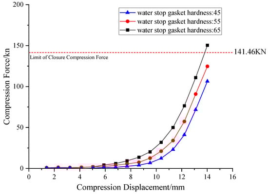
Figure 7.
Compression closing force curve of gaskets under different rubber hardness.
The results indicate that the 65° hardness sample exceeds the design upper limit and fails to meet the requirements for the assembly phase, while the other two groups satisfy the design requirements.
Using the gasket’s central axis as x = 0 for a local coordinate system (with the outside as negative and inside as positive), an analysis of the most unfavorable conditions was conducted. This yielded the contact stress distribution for the upper and lower potential leakage paths (Figure 8 and Figure 9).
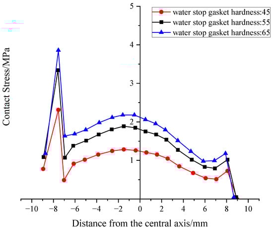
Figure 8.
Distribution of Contact Stress on the Upper Part of Gaskets under Different Hardness.
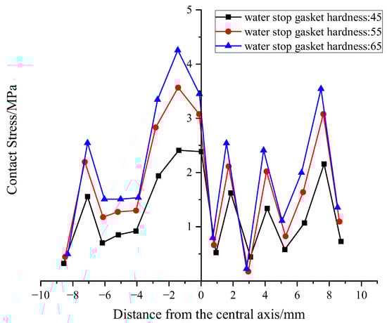
Figure 9.
Distribution of Contact Stress at the Bottom of Gaskets under Different Hardness.
From the curves, it’s clear that the peak stress in the outer region is significantly higher than in the inner region. These peaks are located near the pointed rib-neck and the outer foot, respectively.
We extracted the average contact stress to serve as a waterproofing criterion. The results show that for every 10° increase in hardness, the average contact stress on the upper and lower surfaces increases by approximately 0.35 MPa, demonstrating a linear relationship in this increase.
Overall, the pointed rib structure can improve the sealing performance of the upper surface without significantly increasing the overall reaction force. When the hardness increases from 45° to 55°, there’s a marked improvement in waterproofing performance. However, increasing it further to 65°, while further inhibiting leakage, introduces assembly risks. Therefore, the recommended hardness range is 50–60°.
5.2. The Influence of Height
The geometric configuration of the sealing gasket, particularly its body height, is another critical factor affecting its mechanical and sealing performance. Considering typical installation space constraints, body heights of H = 10 mm, 12 mm, and 14 mm (corresponding to Operating conditions 1, 4, and 5) were selected to investigate the influence of height on gasket performance.
Figure 10 displays the compression-closure force curves for gaskets of different heights. Compared to hardness, body height primarily influences stiffness by changing the aspect ratio of the cross-section and the effective compression area. The curves show that for the same compression amount, a smaller H results in a smaller closure force. The 10 mm sample generated a reaction force of 112.9 kN at 2 mm compression, which is 36.7% lower than the 14 mm sample. When H = 14 mm, the reaction force reached 178.5 kN, exceeding the ultimate closure compression force, which might affect the assembly process.
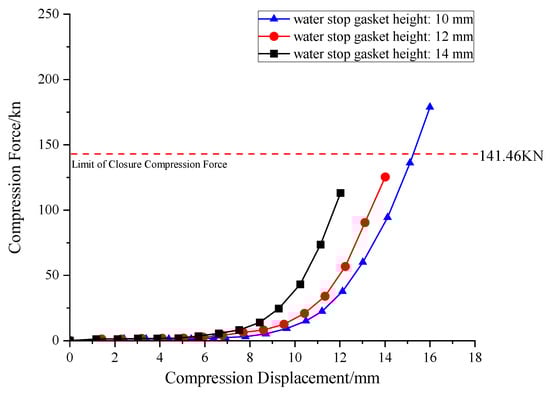
Figure 10.
Compression closing force curve of gaskets at different heights.
This phenomenon occurs because the target compression height is a fixed value. Gaskets with a larger initial height H will have larger absolute compression displacement (ΔH = H − 2 mm) and relative compression strain (ϵ = ΔH/H). According to the hyperelastic constitutive properties of rubber materials, the increase in stress is exponential with respect to strain; therefore, higher strain necessarily leads to a sharp increase in macroscopic reaction force.
Figure 11 and Figure 12 present the contact stress curves for the height variable, and the average contact stress was statistically analyzed. Overall, penetration path 1 significantly outperforms penetration path 2, which also validates the promoting effect of the pointed rib on sealing. As seen in the data, the contact stress increases with H from 12 mm to 14 mm in a linear-exponential mixed growth pattern. The 14 mm group showed a 77% increase in contact stress in the upper channel compared to the 12 mm group, but the compression reaction force also increased by 58%, indicating a “diminishing returns” phenomenon. Based on a comprehensive analysis, increasing H to 12 mm can significantly enhance sealing without excessively increasing the reaction force. Further increases to 14 mm or above should be comprehensively weighed against construction convenience.
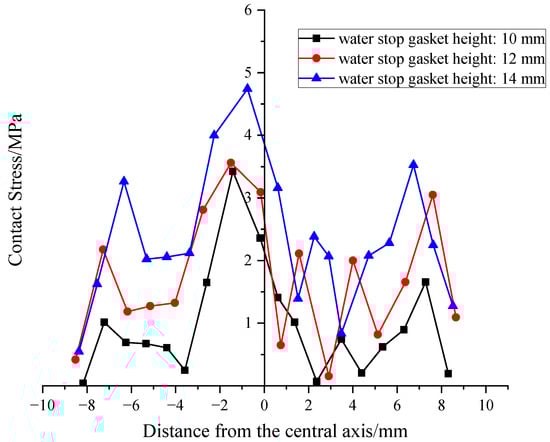
Figure 11.
Distribution of contact stress on the upper part of the gasket at different heights.
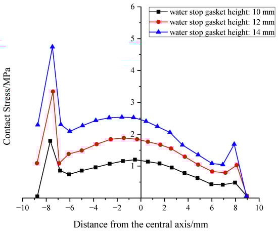
Figure 12.
Distribution of contact stress at the Bottom of gasket at different heights.
5.3. The Influence of Width
The body width of a sealing gasket directly determines its contact area with mating surfaces and its material volume, making it a critical geometric parameter affecting overall performance. To explore the influence of cross-sectional width B on the gasket’s load-bearing and sealing mechanism, three sample groups were selected, namely B = 12 mm, 14 mm, and 16 mm (working conditions 1, 6, and 7), while keeping other geometric parameters and material properties constant.
Figure 13’s compression-closure force curves show that the gasket’s closure force increases almost linearly with its body width. At the design compression height, when the width increased from 12 mm to 14 mm, the closure force rose from 105.80 kN to 125.13 kN (an 18.3% increase). When the width further increased to 16 mm, the closure force reached 149.22 kN (another 19.2% increase). The increase is approximately linear, mainly because a wider gasket increases the effective compression area and bending stiffness, requiring a greater total force for the same compression strain.
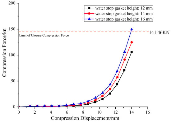
Figure 13.
Compression closing force curves of gaskets with different widths.
At the sealing performance level, the influence mechanism of width exhibits its uniqueness. Interestingly, increasing the width didn’t significantly boost the peak contact stress. Instead, its core contribution lies in significantly broadening the coverage area of the high-stress region and effectively extending the potential leakage path. As shown in Figure 14 and Figure 15, wider gaskets have a more robust contact stress distribution at the shoulder and foot. The peak consistently appears at the outer pointed rib-neck or foot, with a slight increase in peak value (<8%) as B increases. However, the contact stress at the shoulder and foot significantly improved (up to +23%), effectively extending the potential leakage path. When measured by average contact stress, this method of stress optimization is equivalent to building a “wider waterproof barrier” on the sealing surface, greatly enhancing the reliability and redundancy of the seal. This is crucial for resisting non-uniform wear or imperfections on the sealing surface.
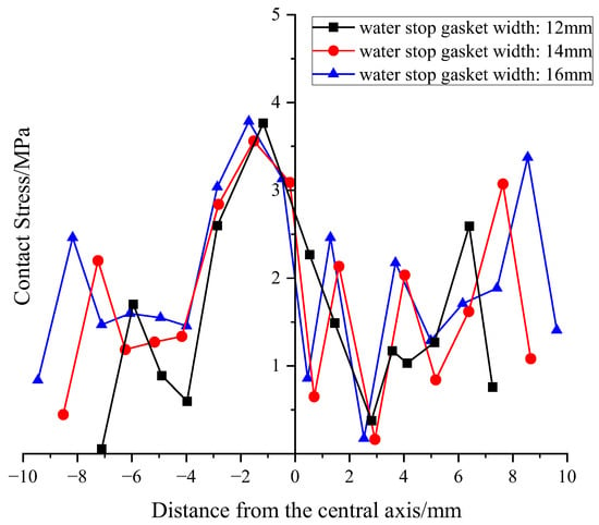
Figure 14.
Distribution of contact stress on the upper part of the gasket under different widths.
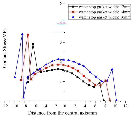
Figure 15.
Distribution of contact stress at the bottom of gasket under different widths.
5.4. The Influence of Inner Diameter
To assess the sensitivity of the sealing gasket’s inner diameter to the bolt clearance, three conditions with inner diameters (d) of 28 mm, 33 mm, and 38 mm (corresponding to working conditions 1, 8, and 9) were analyzed.
Analyzing the compression-closure force curves in Figure 16 reveals a clear trend: the gasket’s closure compression force exhibits a strong positive correlation with its inner diameter. When the inner diameter was 28 mm, the closure force was 125.13 kN. As the inner diameter increased to 33 mm and 38 mm, the closure force correspondingly climbed to 146.26 kN and 168.34 kN. This trend can primarily be attributed to the total material volume of the gasket: assuming constant cross-sectional geometry and outer diameter, the gasket’s total material volume is approximately proportional to its circumference, and thus directly related to its inner diameter. Therefore, a larger inner diameter means more material is involved in load-bearing, leading to a correspondingly higher accumulated macroscopic compression reaction force under the same compression strain. Under this influence, only the 28 mm inner diameter option met the closure force design specifications.
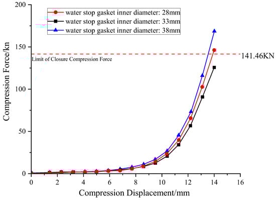
Figure 16.
Compression closing force curve of gaskets with different inner diameters.
However, regarding the crucial sealing performance, the influence of the inner diameter shows a completely different pattern. As depicted in Figure 17 and Figure 18, the distribution of contact stress remains almost unchanged across different inner diameters. Quantitative data shows that when the inner diameter significantly increased from 28 mm to 38 mm (an increase of nearly 36%), the average contact stress on the upper and lower surfaces increased by less than 3% (from 1.72 to 1.76 MPa, and from 1.44 to 1.48 MPa). This result indicates that, within the studied range, the gasket’s sealing performance is almost insensitive to changes in inner diameter.
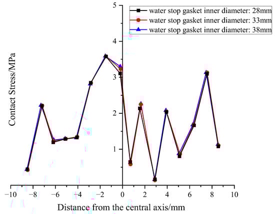
Figure 17.
Distribution of contact stress on the upper part of gaskets with different inner diameters.
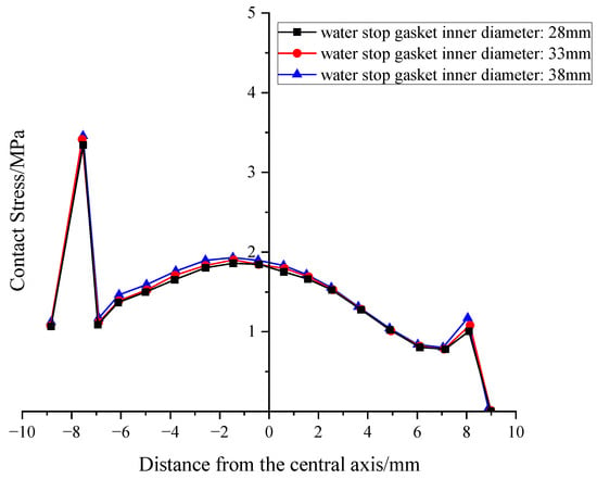
Figure 18.
Distribution of contact stress at the bottom of gasket under different inner diameters.
Considering both closure force and sealing performance, a clear design conclusion can be drawn: the sealing gasket’s inner diameter is a geometric parameter that is “sensitive to closure force, but insensitive to sealing performance.” Therefore, in design practice, the optimal strategy is to choose the smallest possible inner diameter while satisfying structural assembly requirements (such as leaving sufficient bolt clearance). This choice can effectively reduce the gasket’s closure compression force without sacrificing any waterproofing capability, making it easier to meet engineering specifications and thus optimizing overall performance.
5.5. Optimal Design of Sealing Gaskets for Bolt Holes
After compiling the simulation results for sealing gaskets under various working conditions and comprehensively considering both the closure compression force design specifications and the waterproofing performance design specifications for the most unfavorable conditions, the design configuration of a sealing gasket with a hardness of 55°, a height of 12 mm, a width of 14 mm, and an inner diameter of 28 mm is selected as the optimal new waterproofing solution for bolt holes.
6. Test Conditions and Results
6.1. Test Apparatus
The waterproofing performance of the previously designed Sealing Gasket for bolt holes was validated using a self-developed double-seal gasket waterproofing test apparatus, specifically designed to account for bolt holes.
The test setup includes two grooves, an inner and an outer, both of identical dimensions. These grooves can accommodate frame-shaped Sealing Gaskets as needed for the experiment. Their dimensions and the cross-sectional shape of the Sealing Gaskets perfectly match those used in the numerical simulation.
A bolt hole box is situated between the two grooves. This box contains a water passage that connects the main cavity with the bolt hole. The exterior of the bolt hole box features a chamfer, allowing for the installation of a water-swellable rubber sealing ring at this chamfer, depending on test requirements. Inside the bolt hole box, there are two different sizes of internal threads, which allow for either the complete sealing of the bolt hole box channel with a Sealing bolt or the installation of a water-swellable rubber ring, based on the specific test needs. The test setup and a schematic of the waterproofing test are shown in Figure 19 and Figure 20.
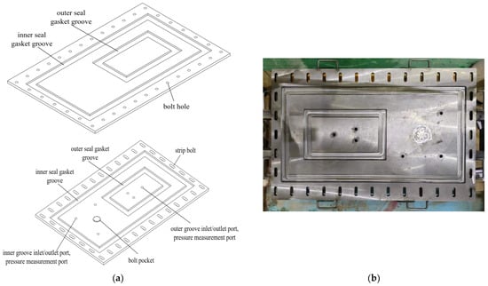
Figure 19.
Test apparatus: (a) Schematic diagram of the test apparatus. (b) Physical diagram of the test apparatus.
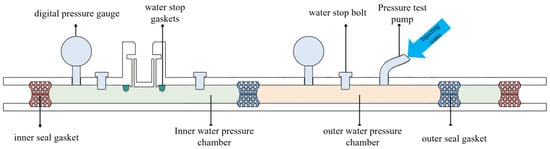
Figure 20.
Consider the layout of waterproof test for double sealing gasket with sealing gasket.
6.2. Test Methods
We started by thoroughly cleaning the mold grooves and the Sealing Gaskets. We then bonded the gaskets with neoprene adhesive and cured them under pressure for 24 h. Concurrently, the water-swellable rubber rings meant for bolt hole waterproofing were immersed in water for 72 h to ensure full expansion.
Once preparations were complete, we assembled the test mold, precisely setting the desired misalignment and opening by adjusting the bolts. Finally, we installed the bolt assembly, connected the pressure gauge and test pump, and filled the sealed chamber with water, completing the setup of the entire test apparatus.
The testing phase employed a step-by-step pressure loading approach. We increased pressure in increments of 0.1 MPa, maintaining each pressure level for 5 min. During this time, we closely monitored pressure changes and any signs of leakage. We continued loading until clear, sustained leakage appeared at either the inner channel Sealing Gasket or the bolt hole, marking the failure of the waterproofing system. Ultimately, the “water resistance pressure” for this condition was determined as the stable pressure value before the pressure level that caused failure. Some of the test steps are shown in Figure 21.
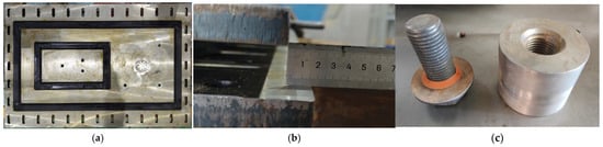
Figure 21.
Test methods: (a) Attach the Sealing Gasket. (b) Adjust the misalignment. (c) Install the bolts and Sealing Gasket.
6.3. Results and Discussion
During the waterproofing tests, we used a digital pressure gauge to read the internal cavity water pressure. We stopped pressurizing as soon as water leakage was observed in the bolt hole box, deeming the pressure level immediately preceding this leakage as the water resistance pressure of the Sealing Gasket. We collected test data for four categories, encompassing eight different conditions, as detailed in Table 3. Notably, the Sealing Gasket waterproofing test aimed to validate numerical simulation results, with the experimentally measured water resistance pressure of the Sealing Gasket being 1.4 MPa, closely matching the simulation.
Table 3.
Waterproof performance test data of joint gasket.
To better understand the performance of our new Sealing Gasket, we also tested the waterproofing capabilities of traditional water-swellable rubber gaskets. Results showed that in the water-swellable rubber condition with an 8 mm opening and 0 mm misalignment, the maximum water pressure recorded by the inner channel digital pressure gauge was 0.39 MPa. This low value occurred because leakage from the outer Sealing Gasket caused a rapid, short-term surge in inner channel water pressure, exceeding the water-swellable rubber ring’s waterproofing capacity. Consequently, leakage appeared at the bolt hole, and the internal cavity pressure subsequently dropped and stabilized at the water resistance pressure of the water-swellable rubber ring. Ultimately, the system’s waterproofing performance was significantly lower compared to a standard double-seal gasket setup.
In contrast, during the tests with our novel Sealing Gasket, the maximum water pressure recorded by the inner channel digital pressure gauge was 1.35 MPa. Similarly to the previous case, leakage from the outer Sealing Gasket led to the inner channel water pressure exceeding the Sealing Gasket’s waterproofing capability, resulting in leakage at the bolt hole. The internal cavity pressure then decreased and stabilized at the Sealing Gasket’s water resistance pressure. Crucially, the final system waterproofing performance showed an approximate 8.82% improvement compared to the water-swellable rubber gasket condition.
Comparing the two bolt hole waterproofing scenarios, a clear pressure difference consistently existed between the inner and outer cavities throughout the test due to the influence of the bolt hole. In both cases, the reason for waterproofing failure was leakage from the bolt hole, highlighting bolt hole waterproofing as the weakest link in the double-seal gasket system. By contrasting the improvement in waterproofing performance across different conditions, it became clear that the inner cavity water pressure affects how much the system’s waterproofing can improve. Since the inner cavity water pressure is directly tied to the bolt hole waterproofing solution, enhancing the bolt hole’s waterproofing capability allows the double-seal gasket to achieve its full waterproofing potential.
Figure 22 shows the pressure-time curve for the water resistance test of a double-sealed gasket, utilizing a novel sealing gasket as the bolt hole waterproofing solution, under conditions of an 8 mm opening and 0 mm misalignment.
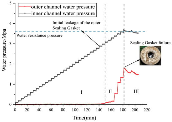
Figure 22.
The pressure-time curve for the water resistance test of a double-sealed gasket using sealing gaskets for waterproofing, with an opening of 8 mm and a misalignment of 0 mm.
From the curve, it’s evident that the pressure in the internal chamber gradually increases with each rise in water pressure. When the water pressure incrementally reached 3.1 MPa, the outer seal gasket experienced its initial leakage. The internal chamber pressure (Pi) rose significantly, indicating that the initial water resistance pressure of the outer seal gasket under these conditions was 3.0 MPa. Even after the outer seal gasket began to leak, the water pressure continued to increase. This is because the internal water pressure exerted a counter-force on the outer seal gasket, effectively repairing its leakage path and allowing the external chamber pressure (Po) to continue rising. As the external chamber pressure (Po) increased step by step, the internal chamber pressure (Pi) also rose in a staggered manner. This demonstrates a “dynamic” increase in the waterproofing capability of the outer seal gasket due to the combined effects of internal and external water pressure.
When the external chamber pressure (Po) reached 3.80 MPa, the internal chamber pressure (Pi) reached the limit of the bolt hole’s waterproofing capacity. The sealing gasket failed to prevent water ingress, and the internal chamber pressure could no longer increase, thereby limiting the further improvement of the outer seal gasket’s waterproofing capability. After the bolt hole leakage occurred, the external chamber pressure (Po) stabilized around the water resistance pressure of 3.7 MPa, and the internal chamber pressure (Pi) stabilized around the sealing gasket’s water resistance pressure of 1.4 MPa. The pressure gauges for both the internal and external chambers consistently showed a pressure differential. This suggests that even when leakage occurs in a double-sealed gasket waterproofing system that uses a sealing gasket for bolt hole waterproofing, the improved waterproofing performance of the outer seal gasket persists.
In the double-sealed gasket waterproofing test, where a sealing gasket was used as the bolt hole waterproofing solution with an 8 mm opening and 0 mm misalignment, the water pressure at which the bolt hole waterproofing failed was the previous water pressure level, which was 3.7 MPa. Due to the internal water pressure exceeding the sealing gasket’s waterproofing capacity, leakage occurred at the bolt hole. Under this water resistance pressure, the maximum reading on the internal chamber pressure gauge was 1.35 MPa.
We analyzaed the water pressure changes of the double-sealed gasket with the novel sealing gasket bolt hole waterproofing solution under conditions of an 8 mm opening and 15 mm misalignment. This scenario best illustrates the function of the new bolt hole waterproofing system. Figure 23 shows the pressure-time curve for this condition, from which we can clearly observe the following processes:
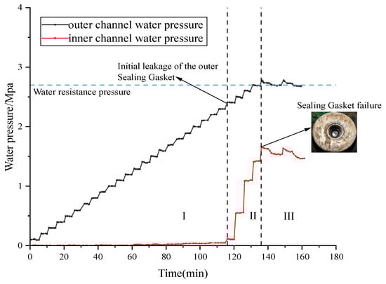
Figure 23.
The pressure-time curve for the water resistance test of a double-sealed gasket using sealing gaskets for waterproofing, with an opening of 8 mm and a misalignment of 15 mm.
Initial Sealing Phase: In the initial loading stage, the external chamber water pressure (Po) rises in a stepped manner, while the internal chamber water pressure (Pi) consistently remains close to zero. This indicates that, at this point, only the outer sealing gasket is independently bearing and resisting the external water pressure.
Initial Leakage and Dynamic Enhancement: When the external chamber water pressure (Po) reaches 2.4 MPa, the outer sealing gasket experiences its first leakage, causing the internal chamber water pressure (Pi) to begin rising sharply. This shows that the initial sealing pressure threshold for the outer sealing gasket was the previous pressure level, which is 2.4 MPa. Interestingly, even after the initial leakage, the external chamber water pressure (Po) can continue to increase. The mechanism behind this is that the establishment of internal chamber water pressure (Pi) creates a backpressure effect on the outer sealing gasket, causing some of the original leakage pathways to be re-sealed. As a result, the waterproofing performance of the outer sealing gasket undergoes a “dynamic enhancement.”
Ultimate Failure Phase: As the external chamber water pressure (Po) continues to load up to 2.88 MPa, the internal chamber water pressure (Pi) reaches approximately 1.4 MPa and then can no longer rise, stabilizing instead. This marks the point where the inner sealing gasket reaches its waterproofing limit, and the entire waterproofing system experiences final leakage.
Post-Leakage State: After the system fails, the external and internal chamber water pressures eventually stabilize around 2.8 MPa and 1.4 MPa, respectively. The consistent pressure difference between the two (ΔP ≈ 1.4 MPa) strongly demonstrates that even after the overall system leaks, the pressure-bearing and waterproofing enhancement effect of the outer sealing gasket still persists, meaning the entire system has not completely failed.
Based on the analysis, the waterproofing process of the double-sealed bolt hole, utilizing a sealing gasket, can be clearly divided into three stages:
Stage I: Single-Channel Independent Waterproofing Stage. At lower water pressures, only the outer sealing gasket is active, and there’s no water pressure in the inner chamber.
Stage II: Dual-Channel Collaborative Waterproofing Stage. Once the outer sealing gasket starts to leak, the inner chamber begins to bear pressure. The backpressure from the inner chamber water helps repair or seal some of the leakage paths in the outer sealing gasket, dynamically enhancing its waterproofing capability. This is when the inner and outer sealing gaskets work together collaboratively.
Stage III: Ultimate Failure Stage. When the inner chamber water pressure reaches the waterproofing limit of the inner sealing gasket, an irreversible leak occurs at the bolt hole. At this point, the inner sealing gasket becomes the bottleneck for waterproofing capability, not the outer one. Ultimately, the inner and outer water pressures stabilize with a fixed pressure difference, and the system exhibits the characteristic of “failure without collapse”.
Through the research outlined above, an initial optimization strategy for the double-sealed gasket waterproofing system can be proposed.
The outer sealing gasket is the primary waterproofing component of the double-sealed gasket system, and it determines the system’s initial waterproofing performance. Therefore, a key focus should be on strengthening the waterproofing capability of the outer sealing gasket.
In the double-sealed gasket waterproofing system, the extent to which the outer sealing gasket’s waterproofing performance improves is linked to the internal chamber pressure. The maximum pressure the inner chamber can withstand, in turn, depends on the bolt hole waterproofing performance. Consequently, the priority for bolt hole waterproofing should be the same as that for the inner sealing gasket. The design standards for the inner sealing gasket shouldn’t match those of the outer sealing gasket; instead, they should align with the design standards for bolt hole waterproofing. The inner sealing gasket’s waterproofing performance can be relatively weaker, consistent with the bolt hole’s waterproofing performance. This approach not only reduces the difficulty of segment assembly but also helps to control costs.
7. Conclusions
This paper addresses the insufficient waterproofing performance of traditional bolt hole waterproofing solutions by designing a novel approach. It establishes a 3D finite element model for a sealing gasket and optimizes its key design parameters. Finally, waterproofing performance tests were conducted on the sealing gasket, exploring the waterproofing capabilities of a double-seal gasket system when the sealing gasket is used as a bolt hole waterproofing solution. This further illustrates the sealing gasket’s contribution to improved waterproofing performance. The main conclusions are as follows:
(1) During compression, the sealing gasket exhibits significant radial outward extrusion deformation due to the coupling of pointed ribs and friction. A 2D planar assumption can’t accurately describe the stress-deformation state. Using a 3D finite element model allows for a more realistic capture of stress migration and local peak values.
(2) Hardness, gasket height, and width all simultaneously influence both the closure compression force and sealing performance. The inner diameter, however, primarily affects the closure compression force, with its contribution to average contact stress being negligible. The combined optimization results recommend a hardness of 55°, a height of 12 mm, a width of 14 mm, and an inner diameter of 28 mm. This configuration can increase the average contact stress in the upper and lower channels to 1.72 MPa and 1.44 MPa, respectively, while meeting the ultimate closure compression force of 140 kN. Experimental verification of its water resistance pressure confirms this, and its sealing performance remains unaffected by installation misalignment. This indicates that the design offers both excellent sealing and engineering robustness.
(3) The sealing improvement of the outer sealing gasket increases with rising internal cavity water pressure. The sealing gasket, acting as a bolt hole waterproofing component, significantly lengthens the leakage path and shares the load of the outer channel, creating a “bolt hole—inner channel—outer channel” triple defense line.
(4) In the design process of a double-seal gasket waterproofing system, it’s crucial to significantly enhance the waterproofing capability of the outer sealing gasket. The priority for bolt hole waterproofing should be the same as that for the inner sealing gasket. The design standard for the inner sealing gasket doesn’t need to match that of the outer sealing gasket; instead, it can refer to the bolt waterproofing performance design indicators.
Author Contributions
Conceptualization, methodology, writing—original draft, Y.Y.; formal analysis, investigation, writing—original draft, G.Z.; methodology, software, writing—review and editing, funding acquisition, W.Z.; investigation, resources, validation, Y.L.; data curation, software, X.Z. All authors have read and agreed to the published version of the manuscript.
Funding
This study is supported by the Science and Technology Research and Development Plan Project of China Railway Group Limited (Grant Nos. 2021-Major-14; N2023G043), which are gratefully acknowledged.
Data Availability Statement
The data presented in this study are available upon request from the corresponding author.
Conflicts of Interest
Author Yong Yu was employed by the China Railway Liuyuan Group Co., Ltd. The remaining author declares that the research was conducted in the absence of any commercial or financial relationships that could be construed as a potential conflict of interest.
References
- Zhang, Y.; Yao, Z.; Wei, C.; Zhang, X.; Zhao, X.; Wu, R.; Cheng, X. Discussion on Main Issues of Shield Tunnel Waterproofing Technology and Its Future Prospect. Tunn. Constr. 2022, 42, 1832–1843. [Google Scholar] [CrossRef]
- Zhang, W.; Yang, Y.; Zhang, C.; Zhang, G.; He, L.; Lv, J. Dynamic Autonomous Deviation Correction of Super-Large Diameter Shield Tunnel Rings Based on Multi-Objective Control Techniques. China J. Highw. Transp. 2023, 36, 231–243. [Google Scholar] [CrossRef]
- Xiao, M.; Xie, H.; Wang, S.; Zhong, Y. Evolution and Prospects of Shield Tunnel Joints and Segment Waterproofing Systems. Tunn. Constr. 2021, 41, 1891–1902. [Google Scholar] [CrossRef]
- Gong, C.; Ding, W.; Soga, K.; Mosalam, K.M.; Tuo, Y. Sealant Behavior of Gasketed Segmental Joints in Shield Tunnels: An Experimental and Numerical Study. Tunn. Undergr. Space Technol. 2018, 77, 127–141. [Google Scholar] [CrossRef]
- Zhang, Y.; Feng, S.; You, G.; Wen, Z. Study on Waterproof Mechanism of Shield Tunnel Joints Considering Water Pressure Process. Tunn. Constr. 2020, 40, 1594–1601. [Google Scholar] [CrossRef]
- Zhang, W.; Zhang, G.; Li, H.; Gao, W.; Guo, W.; Gao, P. Waterproof Performance of Sealing Gaskets and Impact of Construction Loads on Segment Joints in Shield Tunnel. China J. Highw. Transp. 2020, 33, 130–141. [Google Scholar] [CrossRef]
- Zhang, Q.; Xie, L.; Zhao, Z.; Zhao, W.; Ma, Y.; Shi, L.; Zhang, Z. Mechanical Behavior and Waterproof Performance of Longitudinal Section of Tunnel Segment Joint Gasket. Sci. Rep. 2024, 14, 10549. [Google Scholar] [CrossRef]
- Gong, C.; Ding, W. Waterproof Properties of Elastic Sealing Gaskets Used in Segmental Joints of Large-Diameter Underwater Shield Tunnels: Design Methodology and Engineering Guidance. Tunn. Constr. 2018, 38, 1712–1722. [Google Scholar] [CrossRef]
- Ding, W.; Gong, C.; Mosalam, K.M.; Soga, K. Development and Application of the Integrated Sealant Test Apparatus for Sealing Gaskets in Tunnel Segmental Joints. Tunn. Undergr. Space Technol. 2017, 63, 54–68. [Google Scholar] [CrossRef]
- Li, R.; Wang, Y.; Gong, C.; Wang, F.; Ding, W. Prediction of Long-Term Waterproof Performance of Ethylene Propylene Diene Monomer Sealing Gasket. Tunn. Constr. 2024, 44, 293–300. [Google Scholar] [CrossRef]
- Zhang, G.; Zhang, W.; Li, H.; Cao, W.; Wang, B.; Guo, W.; Gao, P. Waterproofing Behavior of Sealing Gaskets for Circumferential Joints in Shield Tunnels: A Full-Scale Experimental Investigation. Tunn. Undergr. Space Technol. 2021, 108, 103682. [Google Scholar] [CrossRef]
- Zhang, D.; Chen, S.; Huang, Z.; Zhang, Z.; Su, L. Waterproofing Performance of Longitudinal Segmental Tunnel Joints under External Loads: A Full-Scale Experimental Investigation. J. Zhejiang Univ.-Sci. A 2024, 25, 991–1005. [Google Scholar] [CrossRef]
- Gong, C.; Xie, C.; Zhu, H.; Yan, Z. Multi-Criteria Evaluation Model of Rubber Sealing Gasket for Shield Tunnel Joint. Tunn. Undergr. Space Technol. 2026, 168, 107127. [Google Scholar] [CrossRef]
- Yang, S.; Wu, H.; Chen, R.; Cui, Q.; Yang, L. Influence of Distribution Form of Double-Sealing Gaskets on Mechanica Properties of Joints in Large-Diameter Shield Tunnels. Tunn. Constr. 2024, 44, 750–762. [Google Scholar] [CrossRef]
- Ma, T.; Wang, S.; Xie, H.; Zhang, C. Layout Modes of Double Sealing Gaskets Outside Bolt Hole of Segment Joint. Tunn. Constr. 2022, 42, 1780–1788. [Google Scholar] [CrossRef]
- Lu, Z.; Ma, T.; Xie, H.; Zhang, Y.; Wang, S.; He, C. Research on Waterproof Performance of New Joint Double Sealing Gasket for Large Diameter Cross-River Shield Tunnel Segments. Railw. Stand. Des. 2022, 66, 109–116. [Google Scholar] [CrossRef]
- Li, X.; Hui, P.; Zhou, S.; Huang, D.; Huang, Q. Test Research on Watertight Mechanism and Failure Model of the Double Sealing Gaskets in Shield Tunnel. J. Railw. Sci. Eng. 2020, 17, 159–166. [Google Scholar] [CrossRef]
- Zhang, Z.; Sun, J.; Zhu, Y.; Huang, X.; Yuan, W. Experimental Study on Waterproof Performance of Joint Seal for Deeply-Buried Storage and Drainage Tunnel. J. ZheJiang Univ. (Eng. Sci.) 2018, 52, 431–439. [Google Scholar] [CrossRef]
- Xiao, M.; Xue, G.; Zhong, Y.; Sun, W. Experimental Research on the Waterproof of Double Gaskets in Segment Joint of Shield Tunnel. J. Railw. Eng. Soc. 2021, 38, 85–91. [Google Scholar] [CrossRef]
- Xie, H.; Wang, S.; He, C.; Ma, T.; Peng, X.; Li, P. Performance of a New Waterproof System with Double Sealing Gaskets Outside Bolt Hole of Segment. Tunn. Undergr. Space Technol. 2022, 119, 104206. [Google Scholar] [CrossRef]


Disclaimer/Publisher’s Note: The statements, opinions and data contained in all publications are solely those of the individual author(s) and contributor(s) and not of MDPI and/or the editor(s). MDPI and/or the editor(s) disclaim responsibility for any injury to people or property resulting from any ideas, methods, instructions or products referred to in the content. |
© 2025 by the authors. Licensee MDPI, Basel, Switzerland. This article is an open access article distributed under the terms and conditions of the Creative Commons Attribution (CC BY) license (https://creativecommons.org/licenses/by/4.0/).