Abstract
Soft open point (SOP) offers a viable alternative to traditional tie switches for optimizing power flow distribution between connected feeders, thereby improving power quality and enhancing the reliability of distribution networks (DNs). Among existing medium-voltage (MV) SOP demonstration projects, the modular multilevel converter (MMC) back-to-back voltage source converter (BTB-VSC) is the most commonly adopted configuration. However, MMC BTB-VSC suffers from high cost and significant volume, with device requirements increasing substantially as the number of feeders grows. To address these challenges, this paper proposes a novel star-connected cascaded H-bridge (CHB) STATCOM SOP (SCS-SOP). The SCS-SOP integrates the static synchronous compensator (STATCOM) and low-voltage (LV) BTB-VSC into a single device, enabling reactive power support within feeders and active power exchange between feeders, while achieving reduced component cost and volume, simplified power decoupling control, and increasing power quality management capabilities. The topology derivation, configuration, operational principles, and control strategies of the SCS-SOP are elaborated. Finally, simulation and experimental models of a two-port 3 Mvar/300 kW SCS-SOP are developed, with results validating the theoretical analysis.
1. Introduction
The distribution networks (DNs) are critical infrastructure for the development of distributed smart grids and new power systems, playing a vital role in ensuring reliable and stable power supply [1,2,3]. However, the large-scale integration of distributed generation (DG) has introduced challenges to DNs, including bidirectional power flow, voltage violations, and overload conditions, which significantly impact power quality and the reliable operation of DNs [4,5].
Traditional primary apparatuses, such as tie switches, on-load tap changers (OLTCs) [6], and switchable shunt capacitor banks [7], are widely used to maintain power quality and reliability in DNs. However, their slow response times and extended adjustment periods make them unsuitable for real-time power regulation during frequent distributed generation (DG) fluctuations [8].
Soft open point (SOP) [9] represents an advanced solution that not only performs the functions of traditional tie switches but also addresses the limitations of mechanical switches and mitigates excessive inrush currents during closing [10]. Leveraging the fast response of power electronic devices, SOP offers flexible control methods [11]. Under normal operating conditions, SOP optimizes power flow distribution between connected feeders, improves power quality, and enhances the reliability of power supply in DNs. In the event of a fault, SOP isolates the fault, redirects power flow, and facilitates power supply restoration.
So far, many studies on SOP have primarily focused on the operational optimization of DNs. In [12], a data-driven framework is formulated for the real-time operation of SOP, which improves the DNs performance without requiring accurate network parameters. In [13], an SOP-based strategy for unbalanced active distribution networks is proposed, which reduces power losses and alleviates three-phase imbalance of the upper-level grid. In [14], the microgrid network based on SOP is reconfigured to enhance the resilience of DNs. In [15], a real-time coordinated scheduling method for DNs with SOPs and plug-in electric vehicles within a multi-time-scale framework is developed, aiming to mitigate rapid voltage fluctuations and real-time uncertainties.
In addition, several studies have gradually shifted their focus toward the topology of SOPs. In practice, SOP predominantly adopts back-to-back voltage source converter (BTB-VSC) [16], which is the most common and widely used configuration. BTB-VSC offers advantages such as scalability and robust regulation of active and reactive power flow. Consequently, recent SOP demonstration projects have primarily employed two-level BTB-VSC [17], three-level BTB-VSC [18], and modular multilevel converter (MMC) BTB-VSC [19]. For medium-voltage (MV) DNs, MMC BTB-VSC is particularly suitable due to its low harmonic distortion, high modularity, and excellent scalability.
Despite its many advantages, the MMC BTB-VSC has several significant drawbacks [20]. First, it requires a large number of power switching devices, which greatly increases cost and complicates control. Second, each sub-module of the MMC necessitates a large DC capacitor, further raising the cost and size of the equipment. Finally, as the MMC BTB-VSC expands to accommodate multiple feeders, the number of required devices grows exponentially.
To overcome these challenges, several novel SOP topologies are proposed. In [21], a multi-port AC-AC-DC converter based on a BTB cascaded H-bridge (CHB) topology is proposed, where the LC series-resonant circuit generates the high-frequency AC bus, and a three-winding high-frequency transformer enables interconnection and expansion of LVDC ports. Nevertheless, when applied to high-power scenarios, the design of the high-frequency transformer becomes highly challenging. In [22], a MMC-based power electronic transformer (PET) topology employing hybrid frequency modulation is proposed, which provides multiple output ports with only three power conversion stages. In [23], each sub-module of the MMC is connected to dual active bridges (DAB) and the output of the DAB is parallelized to form an LVDC bus, thereby ensuring low stress on switching devices and enabling decoupled control. In [24], the sub-module of the MMC shares one bridge arm with the DAB, which reduces the number of power devices and improves power density. However, these topologies are essentially full-power configurations, where flexible interconnection is achieved at the expense of increased device cost and volume, which limits their application as SOPs in DNs.
Aiming to reduce the cost and volume of the full-power MV SOP, this paper proposes a star-connected cascaded H-bridge (CHB) static synchronous compensator (STATCOM) SOP (SCS-SOP) topology. The primary contributions of this paper are summarized as follows.
- (1)
- The SCS-SOP employs a low-voltage (LV) BTB-VSC to achieve partial-power regulation between MV feeders. By integrating STATCOM and BTB-VSC into a single device, the SCS-SOP significantly reduces the cost and volume compared to these full-power SOP topologies.
- (2)
- The operating principle of the SCS-SOP is described in detail. In this topology, the STATCOM regulates reactive power within feeders and the BTB-VSC controls active power between feeders, which eliminates the need for complex power decoupling control and enables straightforward control strategies.
- (3)
- The SCS-SOP can simultaneously regulate the active power between feeders and the reactive power within feeders, which is beneficial for mitigating voltage violations and enhancing power quality.
The rest of this paper is organized as follows: Section 2 introduces the topology derivation and configuration of the SCS-SOP. Section 3 discusses the derivation of power flow regulation and the power regulation range. Section 4 proposes control strategies for the SCS-SOP. In Section 5, the SCS-SOP is compared with the MMC BTB-VSC. Section 6 presents the simulation and experimental results, and Section 7 concludes the paper.
2. Topology of SCS-SOP
2.1. Topology Derivation of SCS-SOP
The topology derivation process of the proposed SCS-SOP is illustrated in Figure 1. A LV BTB-VSC, typically configured as a two-level or three-level structure, is connected to the neutral point of each feeder’s STATCOM. This configuration enables partial-power regulation between feeders through the LV BTB-VSC.
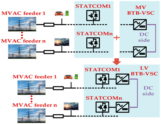
Figure 1.
The topology derivation process of the SCS-SOP.
It is important to note that the SCS-SOP is a partial-power SOP, rather than a full-power SOP. Compared to the scheme that employs both MV STATCOM and MV BTB-VSC, the SCS-SOP integrates reactive power compensation within feeders and flexible interconnection between feeders into a single device. While the power regulation capacity of the SCS-SOP is reduced, it offers significant advantages in terms of cost and volume.
2.2. Topology Configuration of SCS-SOP
For clarity, this paper uses the two-feeder structure of the SCS-SOP as an example to illustrate its operating principle, as shown in Figure 2.
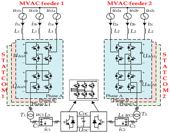
Figure 2.
The topology configuration of the SCS-SOP.
The SCS-SOP comprises two three-phase connected reactors, two STATCOMs, two three-phase isolation transformers, two three-phase LC filters, and one BTB-VSC. The STATCOM provides reactive power compensation within each feeder and consists of three CHB converters, each with N sub-modules. The isolation transformers ensure electrical isolation between the two medium-voltage alternating current (MVAC) feeders. The BTB-VSC, configured with a two-level topology, facilitates flexible interconnection between the feeders.
In Figure 2, us1a, us1b, and us1c represent the three-phase voltages of MVAC feeder 1. STATCOM1 is connected to MVAC feeder 1 through connect reactor L1. i1a, i1b, and i1c denote the three-phase currents of STATCOM1. Udcam, Udcbm, and Udccm (m = 1~N) represent the voltages of the DC capacitors in each sub-module of STATCOM1. up1a, up1b, and up1c are the three-phase voltages at the output of STATCOM1. The neutral point of STATCOM1 is connected to the three-phase isolation transformer T1 with a transformation ratio of n: 1. The secondary side of T1 is connected to filter capacitor C1 and filter inductor L2. uC1a, uC1b, and uC1c denote the three-phase voltages of C1, while iC1a, iC1b, and iC1c represent the corresponding three-phase currents. L2 is connected to the BTB-VSC, whose DC capacitor is CDC, and UDC represents the DC side voltage of the BTB-VSC.
The topology structure on the MVAC feeder 2 side is similar to that of the MVAC feeder 1 side and is therefore not further described.
3. Operating Principle of SCS-SOP
3.1. Power Flow Regulation of SCS-SOP
The single-phase equivalent circuit of the SCS-SOP is depicted in Figure 3, where the voltage on the BTB-VSC side is referred to the primary side of the transformer. In Figure 3a, Us1∠ − θ1 and Us2∠ − θ2 represent the phase-domain voltages of MVAC feeder 1 and feeder 2, respectively. X1 and X2 denote the equivalent connected reactors, while Up1∠ − δ1 and Up2∠ − δ2 are the phase-domain voltages of STATCOM1 and STATCOM2, respectively. Additionally, nUC1∠ − α1 and nUC2∠ − α2 are the phase-domain voltages of the BTB-VSC.
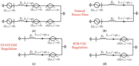
Figure 3.
Single-phase equivalent circuits for each structure of the SCS-SOP. (a) Single-phase equivalent circuits of the SCS-SOP. (b) Natural power flow equivalent circuits. (c) STATCOM regulation equivalent circuits. (d) BTB-VSC regulation equivalent circuits.
According to the circuit superposition theorem, the single-phase equivalent circuit of the SCS-SOP can be decomposed into three single-phase equivalent circuits: natural power flow, STATCOM regulation, and BTB-VSC regulation, as shown in Figure 3b–d.
where l = 1, 2, represents the feeder index. The subscripts 0, p, and c denote the corresponding variables for natural power flow, STATCOM regulation, and BTB-VSC regulation, respectively. Each current in (1) can be expressed as:
where Xl = ωlLl, ωl is the angular frequency of the MVAC feeder, and j is the imaginary unit.
Therefore, the power flow of MVAC feeder l can also be divided into three components, expressed as:
where real() and image() denote the real and imaginary parts of the phasor, respectively. And superscript * represents the conjugate phasor.
The power flow of the natural power flow is expressed as:
The power flow of STATCOM regulation is expressed as:
The power flow of BTB-VSC regulation is expressed as:
From (6), it is evident that by controlling the amplitude Ucl and phase αl of the BTB-VSC, the active and reactive power absorbed or emitted by the BTB-VSC can be decoupled and continuously adjusted. Additionally, adjusting the transformer ratio n can further modify the active and reactive power. Notably, the power that the SCS-SOP can flexibly interconnect corresponds to the active and reactive power transmitted by the BTB-VSC.
3.2. Power Regulation Range of SCS-SOP
The phasor diagram corresponding to Figure 3a is illustrated in Figure 4. As shown in Figure 4, when UCl and Il are in phase or in opposite phase, the active power transmitted by the BTB-VSC reaches its maximum [25]. At this time, according to the corresponding relationships of trigonometric functions, Plmax and Ql are given as follows:
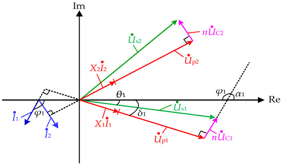
Figure 4.
Phasor diagram of the single-phase equivalent circuit of the SCS-SOP.
Meanwhile, Plmax and Ql satisfy the following equation:
By substituting (7) into (8), Plmax can be expressed as:
The constraint condition for (9) is:
The adjustment range of the active power in the SCS-SOP can be derived from (10). It is evident that when Usl and UCl are fixed, a larger transformer ratio n and reactive power Ql result in a greater maximum active power Plmax.
4. Control Strategies of SCS-SOP
The control strategies of the SCS-SOP are illustrated in Figure 5, encompassing both the control strategies for the STATCOM and the BTB-VSC.
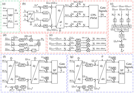
Figure 5.
Control strategies of the SCS-SOP. (a) Phase-locked loop. (b) Current control strategy of the STATCOM. (c) Overall DC voltage control of the STATCOM. (d) Among-Phase DC Voltage Balancing Control of the STATCOM. (e) In-Phase DC Voltage Balancing Control of the STATCOM. (f) Control strategy of the BTB-VSC on the feeder 1 side. (g) Control strategy of the BTB-VSC on the feeder 2 side.
The angular frequency ωl and phase θl of the SCS-SOP are determined using a synchronous reference frame phase-locked loop (SRF-PLL), as shown in Figure 5a. Furthermore, the control strategies for STATCOM1 and STATCOM2 are identical, while the control strategy for the BTB-VSC is divided into the feeder 1 side and the feeder 2 side.
4.1. Current Control Strategy of STATCOM
According to Kirchhoff’s Voltage Law, the relationship between usl and il is expressed as:
Additionally, by applying the Park transformation to (11), the following expression is obtained:
where Ild and Ilq are the dq-axis components of il, respectively. Usld and Uslq are the dq-axis components of usl. Upld and Uplq are the dq-axis components of upl. UCld and UClq are the dq-axis components of uCl. Due to the influence of the connect reactor Ll, coupling exists between the control of Ild and Ilq, necessitating current decoupling control.
The current control strategy for the STATCOM is illustrated in Figure 5b. It employs conventional current decoupling control and voltage feedforward, as is typical in traditional STATCOM [26]. However, the feedforward voltage are Usld−nUCld and Uslq−nUClq instead of Usld and Uslq, which differentiates it from traditional implementations.
In Figure 5b, Ild* is derived from the overall DC voltage control discussed in the next section, while Ilq* is determined by the required reactive current compensation. The zero-sequence voltage u0 is obtained from the among-phase DC voltage balancing control, while uBa1~uBaN, uBb1~uBbN, uBc1~uBcN are derived from in-phase DC voltage balancing control, as described in the next section.
4.2. DC Voltage Control Strategy of STATCOM
This paper adopts a three-layer DC voltage control strategy for the STATCOM [20], which includes overall DC voltage control, among-phase DC voltage balancing control, and in-phase DC voltage balancing control.
The overall DC voltage control of the STATCOM is illustrated in Figure 5c. By summing Udcam, Udcbm, Udccm of each phase and calculating their average, Udca, Udcb, and Udcc are obtained, representing the average DC voltage of each phase sub-module. Subsequently, by summing Udca, Udcb, and Udcc and taking the average, the average DC voltage of all sub-module Udc can be acquired. The difference between the reference average DC voltage Udc* and Udc is input into a PI controller to generate the reference current Ild*.
The among-phase DC voltage balancing control of the STATCOM is shown in Figure 5d, which utilizes zero-sequence voltage injection. Assuming that the STATCOM voltage upl contains both positive-sequence and zero-sequence components, while the STATCOM current il contains only the positive-sequence component. upl and il can be expressed as follows:
where subscripts P and Z denote the positive-sequence and zero-sequence components, respectively.
By combining (13) and (14), the expression for the average three-phase power of the STATCOM is obtained as:
where is the same active power of each phase. ΔPa, ΔPb, and ΔPc are the active power of each phase generated by the zero-sequence voltage, and the sum of ΔPa, ΔPb, ΔPc is zero.
Due to the complexity of calculating the zero-sequence voltage, this paper adopts a simplified approach. It assumes that the STATCOM current is three-phase symmetrical and that the STATCOM compensates only reactive current. Under these assumptions, it can be approximated that φP = π/2.
By substituting φP = π/2 into (15), the relationship between the amplitude and initial phase of zero-sequence voltage is derived as:
Hence, the zero-sequence voltage u0 can be obtained as:
The in-phase DC voltage balancing control of the STATCOM is illustrated in Figure 5e, follows the same approach as the traditional STATCOM [27] and is therefore not further elaborated.
4.3. Control Strategy of BTB-VSC
The feeder 1 side of the BTB-VSC is responsible for controlling the power flow between the two feeders, while the feeder 2 side maintains the DC voltage UDC at a constant level. Since reactive power within each feeder can be compensated by the STATCOM, and there is no requirement for reactive power transfer between feeders, the BTB-VSC is controlled to transfer only active power. The control strategy for the BTB-VSC on the feeder 1 side is illustrated in Figure 5f. Based on the theory of instantaneous reactive power, the power flow of the BTB-VSC on the feeder 1 side is expressed as:
Because the BTB-VSC and the STATCOM are connected in series, the BTB-VSC employs voltage-based control to prevent interference with the current control of the STATCOM. The STATCOM current I1d is approximately 0, allowing the active power outer loop to determine the voltage reference value Uc1q*, thereby enabling active power regulation by the BTB-VSC. The voltage reference value Uc1d* is set to 0. Furthermore, an active damping method based on capacitor current is employed to suppress filter resonance and enhance system stability, with the active damping factor denoted as K.
The control strategy for the BTB-VSC on the feeder 2 side is illustrated in Figure 5g. Unlike the feeder 1 side, this strategy incorporates DC voltage control. The remaining aspects of the control strategy are similar to those of the feeder 1 side and are not further elaborated.
5. Comparison of Topologies
To demonstrate the advantages of the proposed SCS-SOP, this section provides a detailed comparison between SCS-SOP and BTB-MMC SOP. The comparison includes the number of active components, capacitance requirements, and the semiconductor die size, all of which significantly influence the topology’s cost and volume. Additionally, the applicable scenarios for both topologies are discussed.
For fair comparison, both topologies are evaluated using the same MVAC feeder parameters, with a rated voltage of 10 kV and a rated capacity of 3 MW. In the BTB-MMC scheme, the single-feeder side has a capacity of 3 MW, and the sub-modules adopt a half-bridge (HB) structure. Each HB sub-module (HBSM) operates at a DC voltage of 2500 V, with 4500 V Si-based IGBTs. Each bridge arm of the MMC contains 8 HBSMs. In the SCS-SOP scheme, the single-feeder side also has a capacity of 3 MW, with STATCOM sub-modules adopting a full-bridge (FB) structure. Each FB sub-module (FBSM) operates at a DC voltage of 2500 V, with 4500 V Si-based IGBTs. Each bridge arm of the STATCOM contains 4 HBSMs. The BTB-VSC in this scheme has a capacity of 0.3 MW, a DC voltage of 2500 V, and also uses 4500 V Si-based IGBTs.
5.1. Comparison of Number of Active Components
The comparison of the number of active components between the BTB-MMC and the SCS-SOP is presented in Table 1, where l denotes the number of MVAV feeders.

Table 1.
The number of active components.
Figure 6 illustrates the comparison of the number of IGBTs between the BTB-MMC and the SCS-SOP. Compared to the BTB-MMC, the SCS-SOP significantly reduces the number of IGBTs. Notably, the proposed SCS-SOP uniquely integrates the functionalities of STATCOM and LV BTB-VSC, with flexible interconnection primarily achieved through the LV BTB-VSC. Therefore, when comparing only the active components used in the flexible interconnection section, the SCS-SOP employs fewer active components.
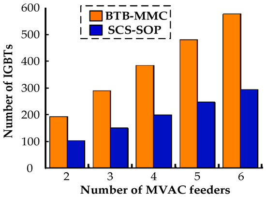
Figure 6.
The number of IGBTs between the BTB-MMC and the SCS-SOP.
5.2. Comparison of Capacitance Requirements
The number and value of capacitors significantly affect the cost and volume of SOP. As shown in Table 1, the number of capacitors required for the SCS-SOP is significantly smaller than that for the BTB-MMC.
According to [25], the parameter design methods for the capacitors of the BTB-MMC HBSMs and the capacitors of the SCS-SOP FBSMs are expressed as:
where CSCS-SOP-1 is the capacitor of the STATCOM, CSCS-SOP-1 is the capacitor of the BTB-VSC. Sn denotes the apparent power of the BTB-MMC, m is the modulation index, ω0 is the fundamental angular frequency, ε is the ripple ratio of the capacitor voltage, with ε = 0.05. Vdc*, Udc*, and UDC* are the rated capacitor voltages of the BTB-MMC, STATCOM, and BTB-VSC, respectively. In is the rated current of the STATCOM, and τ is the time constant, typically less than 0.05 in engineering applications, with τ = 0.04. Sn_vsc denotes the rated power of the BTB-VSC.
According to (19), the total capacitance of the BTB-MMC and SCS-SOP is obtained, as illustrated in Figure 7. It is evident that the capacitors in the BTB-MMC are significantly larger than those in the SCS-SOP. Moreover, the SCS-SOP requires fewer capacitors, making it more advantageous in terms of capacitor cost and volume.
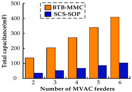
Figure 7.
The total capacitance of the BTB-MMC and the SCS-SOP.
5.3. Comparison of Semiconductor Die Size
Semiconductor utilization is another critical factor influencing the cost and volume of SOP, closely related to the rated current and voltage values. Since both schemes have identical DC capacitor voltages, the rated voltage of the semiconductors is also the same. According to [28], semiconductor utilization can be assessed by the semiconductor die size. The total estimated semiconductor die size, based on 4500 V Si-based IGBT, is calculated as:
where Adie_4500V represents the total estimated semiconductor die size, and I denotes the nominal rated current.
By combining the number of IGBTs from Table 1 with (20), the total estimated semiconductor die size for the BTB-MMC and the SCS-SOP are presented in Figure 8. The proposed SCS-SOP demonstrates superior semiconductor utilization compared to the BTB-MMC, as it requires fewer IGBTs.
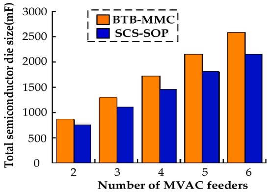
Figure 8.
The total estimated semiconductor die size of the BTB-MMC and the SCS-SOP.
5.4. Comparison of Applicable Scenarios
The SCS-SOP is a partial-power SOP, rather than a full-power SOP. Essentially, the SCS-SOP not only provides reactive power compensation but also utilizes the STATCOM to facilitate voltage reduction. This enables the LV BTB-VSC to perform power transfer between MVAC feeders. However, since the BTB-VSC relies on the STATCOM current for power transfer, it is influenced by the STATCOM current, as indicated in (9).
Consequently, the proposed SCS-SOP is best suited for scenarios requiring reactive power compensation within MVAC feeders, with moderate power transfer demands between feeders. In modern MVAC feeders, STATCOMs are increasingly utilized, and the power transfer requirements between feeders are generally low, making the SCS-SOP a viable solution in certain applications.
In contrast, the BTB-MMC is a full-power SOP, capable of power transfer independent of other topological structures. However, when power transfer demands between MVAC feeders are low, the BTB-MMC offers no significant advantages in terms of cost and volume.
Table 2 provides a detailed comparison between the BTB-MMC and SCS-SOP. While the SCS-SOP outperforms the BTB-MMC in terms of the number of components, capacitance requirements, semiconductor die size, control complexity, and cost and overall volume, these advantages come with reduced power transmission capability and relatively limited application scenarios.
Table 2.
The detailed comparison between two schemes.
6. Simulation and Experimental Verification
The effectiveness and feasibility of the proposed topology and control strategy are verified through a MATLAB/Simulink model and a real-time control-in-the-loop (CIL) experiment using RT-Lab for a two-port SCS-SOP.
6.1. Simulation Verification of SCS-SOP
The simulation parameters for the proposed SCS-SOP, based on two 10 kV MVAC feeders, are listed in Table 3. To verify the effectiveness of the proposed control strategy, four test cases are designed, as detailed in Table 4. The per-unit values in Table 4 are based on the rated capacity of the SCS-SOP provided in Table 3.
Table 3.
Simulation parameters.
Table 4.
Simulation cases.
- (1)
- Case 1 (0–0.5 s): The reactive power Q1 of STATCOM1 and the active power P1_c of BTB-VSC are set to 1 p.u. The reactive power Q2 of STATCOM2 and the active power P2_c of BTB-VSC are set to −1 p.u.
- (2)
- Case 2 (0.5–1 s): Q1 and P1_c are reduced to 0.5 p.u. Meanwhile, Q2 and P2_c are increased to −0.5 p.u.
- (3)
- Case 3 (1–1.5 s): Q1 remains at 0.5 p.u. P1_c is reversed to −0.5 p.u. Q2 remains at −0.5 p.u. And P2_c is reversed to 0.5 p.u.
- (4)
- Case 4 (1.5–2 s): Q1 is increased to 1 p.u. P1_c and Q2 are decreased to −1 p.u. And P2_c is increased to 1 p.u.
The simulation results of the SCS-SOP are presented in Figure 9. Figure 9a depicts the three-phase voltages of MVAC feeder I and feeder II, highlighting differences in amplitude and initial phase between the two feeders. Figure 9b,c show the three-phase currents of STATCOM1 and STATCOM2, which closely follow their command values. Figure 9d illustrates the DC voltages of the BTB-VSC, STATCOM1, and STATCOM2, confirming the effectiveness of the corresponding DC voltage balance control. Figure 9e,f demonstrate the rapid and accurate control of reactive power within feeders and active power between feeders across various cases.
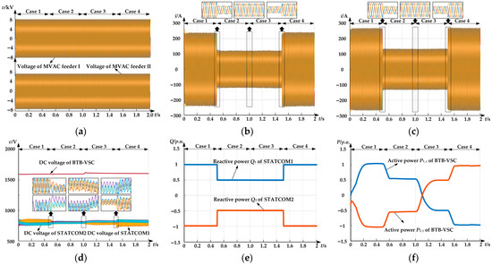
Figure 9.
Simulation results of the SCS-SOP. (a) Three-phase voltages of MVAC feeder I and feeder II. (b) Three-phase current of STATCOM1. (c) Three-phase current of STATCOM2. (d) DC voltages of the BTB-VSC, and average DC voltages of each phase sub-module in STATCOM1/2. (e) Reactive power Q1 of STATCOM1 and reactive power Q2 of STATCOM2. (f) Active power P1_c and P2_c of BTB-VSC.
These simulation results verify that the proposed topology and control strategy effectively enable active power transfer between feeders without compromising the reactive power control of the STATCOM.
6.2. Experimental Verification of SCS-SOP
To further validate the effectiveness of the proposed SCS-SOP, a CIL experiment based on RT-Lab was conducted, as shown in Figure 10.
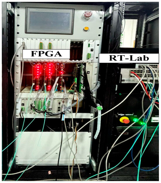
Figure 10.
CIL experiment platform of SCS-SOP based on RT-Lab.
The control algorithms for the SCS-SOP were implemented on a digital signal processor with an FPGA (EP4CE115F23I7), while the hardware circuit of the SCS-SOP was simulated using RT-Lab (OP5600). The experimental parameters were consistent with the simulation parameters provided in Table 3. RT-Lab processed the PWM digital signals from the FPGA and returned analog signals to the FPGA, enabling the control of the SCS-SOP.
The experiment results are presented in Figure 11. Figure 11a,b illustrate the three-phase voltages of MVAC feeder I and feeder II, where slight differences in amplitude and initial phase are observed between the two feeders. Figure 11c,d display the three-phase currents of STATCOM1 and STATCOM2, where the actual currents accurately and rapidly track their reference values, demonstrating the effectiveness of the proposed current control strategy. Figure 11e shows that the DC voltages of the STATCOM and BTB-VSC remain stable despite case variations. The experimental results closely align with the simulation results, further confirming the effectiveness of the proposed topology and control strategy.
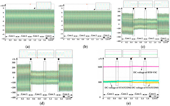
Figure 11.
Experiment results of the SCS-SOP. (a) Three-phase voltages of MVAC feeder I. (b) Three-phase voltages of MVAC feeder II. (c) Three-phase current of STATCOM1. (d) Three-phase current of STATCOM2. (e) DC voltages of the BTB-VSC, and average DC voltages of each phase sub-module in STATCOM1/2.
7. Conclusions
In this paper, a novel SCS-SOP was proposed. Based on the preceding theoretical analysis, the following conclusions are drawn:
- (1)
- By incorporating the BTB-VSC, the STATCOM is innovatively utilized as SOP. Integrating the STATCOM and BTB-VSC into a single device significantly reduces the cost and volume of the components.
- (2)
- The STATCOM regulates reactive power within feeders, while the BTB-VSC regulates active power between feeders. As a result, the SCS-SOP eliminates the need for complex power decoupling control and features a relatively simple control strategy.
- (3)
- The SCS-SOP is capable of coordinating active power flow among feeders while managing reactive power inside feeders, thereby helping to mitigate voltage violations and improve power quality.
- (4)
- Compared to the full-power MMC BTB-VSC, the proposed partial-power SCS-SOP offers advantages in terms of the number of active components, capacitance requirements, and semiconductor die size.
In addition, it is necessary to address the limitation on active power regulated by the BTB-VSC caused by the STATCOM current. Besides the above findings, it is meaningful to evaluate the STATCOM’s ability in SCS-SOP to enhance power quality due to its active power regulation capability.
Author Contributions
Conceptualization, T.L. and Y.L.; methodology, T.L.; software, F.H.; validation, T.L. and Y.L.; formal analysis, G.X.; investigation, T.L.; resources, G.X.; data curation, G.X.; writing—original draft preparation, T.L.; writing—review and editing, G.X.; visualization, G.X.; supervision, G.X.; project administration, T.L.; funding acquisition, T.L. All authors have read and agreed to the published version of the manuscript.
Funding
This research was funded by Guangxi Power Grid Company technology project funding (Project Number: GXKJXM20240190).
Data Availability Statement
There is no additional research data in this article.
Conflicts of Interest
Authors Tianlu Luo, Yanyang Liu and Feipeng Huang were employed by Guangxi Power Grid Co., Ltd. The remaining authors declare that the research was conducted in the absence of any commercial or financial relationships that could be construed as a potential conflict of interest. The Guangxi Power Grid Co., Ltd. had no role in the design of the study; in the collection, analyses, or interpretation of data; in the writing of the manuscript; or in the decision to publish the results.
References
- Gutiérrez, J.S.E.; Téllez, A.A. Optimal Placement of a Unified Power Quality Conditioner (UPQC) in Distribution Systems Using Exhaustive Search to Improve Voltage Profiles and Harmonic Distortion. Energies 2025, 18, 4499. [Google Scholar] [CrossRef]
- Lefeng, C.; Pan, P.; Pengrong, H.; Mengya, Z.; Xiaobo, M.; Wentian, L. Leveraging evolutionary game theory for cleaner production: Strategic insights for sustainable energy markets, electric vehicles, and carbon trading. J. Clean. Prod. 2025, 512, 145682. [Google Scholar] [CrossRef]
- Gan, D.; Ling, H.; Mao, Z.; Gu, R.; Zhou, K.; Lin, K. A Network Partition-Based Optimal Reactive Power Allocation and Sizing Method in Active Distribution Network. Processes 2025, 13, 2524. [Google Scholar] [CrossRef]
- Tang, C.-Y.; Lin, J.-T. Bidirectional Power Flow Control of a Multi Input Converter for Energy Storage System. Energies 2019, 12, 3756. [Google Scholar] [CrossRef]
- Chang, W.-N.; Chang, C.-M.; Yen, S.-K. Improvements in Bidirectional Power-Flow Balancing and Electric Power Quality of a Microgrid with Unbalanced Distributed Generators and Loads by Using Shunt Compensators. Energies 2018, 11, 3305. [Google Scholar] [CrossRef]
- Janiga, K.; Miller, P.; Małkowski, R.; Izdebski, M. An ANN-Based Method for On-Load Tap Changer Control in LV Networks with a Large Share of Photovoltaics—Comparative Analysis. Energies 2024, 17, 5749. [Google Scholar] [CrossRef]
- Wang, Y.; Xu, W. A Shared Resonance Damping Scheme for Multiple Switchable Capacitors. IEEE Trans. Power Del. 2018, 33, 1973–1980. [Google Scholar] [CrossRef]
- He, L.; Tan, Z.; Li, Y.; Cao, Y.; Chen, C. A Coordinated Consensus Control Strategy for Distributed Battery Energy Storages Considering Different Frequency Control Demands. IEEE Trans. Sustain. Energy 2024, 15, 304–315. [Google Scholar] [CrossRef]
- Alanazi, M. Optimal Integration of Distributed Generators and Soft Open Points in Radial Distribution Networks: A Hybrid WCA-PSO Approach. Processes 2025, 13, 1775. [Google Scholar] [CrossRef]
- Lai, Z.; Yi, H.; Wang, Z.; Zhuo, F.; Zhuang, H. Transient Analysis and Overcurrent Limited Strategy for Supply Restoration-Oriented Hybrid Soft Open Point. IEEE Trans. Power Electron. 2024, 39, 2660–2676. [Google Scholar] [CrossRef]
- Liu, Z.; Wang, L. A Robust Strategy for Leveraging Soft Open Points to Mitigate Load Altering Attacks. IEEE Trans. Smart Grid 2022, 13, 1555–1569. [Google Scholar] [CrossRef]
- Huo, Y.; Li, P.; Ji, H.; Yan, J.; Song, G.; Wu, J.; Wang, C. Data-Driven Adaptive Operation of Soft Open Points in Active Distribution Networks. IEEE Trans. Ind. Inf. 2021, 17, 8230–8242. [Google Scholar] [CrossRef]
- Li, P.; Ji, H.; Wang, C.; Zhao, J.; Song, G.; Ding, F.; Wu, J. Optimal Operation of Soft Open Points in Active Distribution Networks Under Three-Phase Unbalanced Conditions. IEEE Trans. Smart Grid 2019, 10, 380–391. [Google Scholar] [CrossRef]
- Ding, T.; Wang, Z.; Jia, W.; Chen, B.; Chen, C.; Shahidehpour, M. Multiperiod Distribution System Restoration With Routing Repair Crews, Mobile Electric Vehicles, and Soft-Open-Point Networked Microgrids. IEEE Trans. Smart Grid 2020, 11, 4795–4808. [Google Scholar] [CrossRef]
- Yang, X.; Xu, C.; Zhang, Y.; Yao, W.; Wen, J.; Cheng, S. Real-Time Coordinated Scheduling for ADNs With Soft Open Points and Charging Stations. IEEE Trans. Power Syst. 2021, 36, 5486–5499. [Google Scholar] [CrossRef]
- Song, S.; Kim, J.; Lee, J.; Jang, G. AC Transmission Emulation Control Strategies for the BTB VSC HVDC System in the Metropolitan Area of Seoul. Energies 2017, 10, 1143. [Google Scholar] [CrossRef]
- Wang, X.; Chen, W.; Zhao, H.; Lan, J.; Chen, Y.; Hao, Z.; Jiang, W.; Mou, X.; Gong, X. A Seamless Integrated Control Method for SNOP Based on BTB-VSC. IEEE J. Emerg. Sel. Top. Power Electron. 2025, 13, 3577–3591. [Google Scholar] [CrossRef]
- Portillo, R.; Prats, M.; Leon, J.; Sanchez, J.; Carrasco, J.; Galvan, E.; Franquelo, L. Modeling Strategy for Back-to-Back Three-Level Converters Applied to High-Power Wind Turbines. IEEE Trans. Ind. Electron. 2006, 53, 1483–1491. [Google Scholar] [CrossRef]
- Akagi, H.; Kitada, R. Control and Design of a Modular Multilevel Cascade BTB System Using Bidirectional Isolated DC/DC Converters. IEEE Trans. Power Electron. 2011, 26, 2457–2464. [Google Scholar] [CrossRef]
- Li, M.; Yang, H.; Zhao, R.; Zheng, T.; Si, C.; Lu, Y.; Yang, Y. Comparative Study on the Operating Area of M3C and B2B MMC for Soft Open Point Application. In Proceedings of the 2019 10th International Conference on Power Electronics and ECCE Asia (ICPE 2019-ECCE Asia), Busan, Republic of Korea, 27–31 May 2019; pp. 1205–1212. [Google Scholar]
- Ma, D.; Chen, W.; Shu, L.; Qu, X.; Gao, S.; Hou, K. A Multiport AC–AC–DC Converter for Soft Normally Open Point. IEEE Trans. Circuit and Syst. II Exp. Briefs 2022, 69, 2146–2150. [Google Scholar] [CrossRef]
- Ma, D.; Chen, W.; Shu, L.; Qu, X.; Zhan, X.; Liu, Z. A Multiport Power Electronic Transformer Based on Modular Multilevel Converter and Mixed-Frequency Modulation. IEEE Trans. Circuit Syst. II Exp. Briefs 2020, 67, 1284–1288. [Google Scholar] [CrossRef]
- Briz, F.; Lopez, M.; Rodriguez, A.; Zapico, A.; Arias, M.; Diaz-Reigosa, D. MMC based SST. In Proceedings of the 2015 IEEE 13th International Conference on Industrial Informatics (INDIN), Cambridge, UK, 22–24 July 2015; pp. 1591–1598. [Google Scholar]
- Yan, Y.; Sun, Y.; Guo, W.; Ji, Z.; Li, D.; Zhao, J. A Novel Modular Multilevel Converter Based Power Electronic Transformer With Integrated Switching Pairs. In Proceedings of the 2022 IEEE Energy Conversion Congress and Exposition (ECCE), Detroit, MI, USA, 9–13 October 2022; pp. 1–8. [Google Scholar]
- Zhang, J.; Feng, X.; Zhou, J.; Zang, J.; Wang, J.; Shi, G.; Cai, X.; Li, Y. Series–Shunt Multiport Soft Normally Open Points. IEEE Trans. Ind. Electron. 2023, 70, 10811–10821. [Google Scholar] [CrossRef]
- Lu, D.; Zhu, J.; Wang, J.; Yao, J.; Wang, S.; Hu, H. A Simple Zero-Sequence-Voltage-Based Cluster Voltage Balancing Control and the Negative Sequence Current Compensation Region Identification for Star-Connected Cascaded H-Bridge STATCOM. IEEE Trans. Power Electron. 2018, 33, 8376–8387. [Google Scholar]
- Lu, D.; Wang, S.; Yao, J.; Yang, T.; Hu, H. Cluster Voltage Regulation Strategy to Eliminate Negative-Sequence Currents Under Unbalanced Grid for Star-Connected Cascaded H-Bridge STATCOM. IEEE Trans. Power Electron. 2019, 34, 2193–2205. [Google Scholar] [CrossRef]
- Marzoughi, A.; Burgos, R.; Boroyevich, D.; Xue, Y. Design and Comparison of Cascaded H-Bridge, Modular Multilevel Converter, and 5-L Active Neutral Point Clamped Topologies for Motor Drive Applications. IEEE Trans. Ind. Appl. 2018, 54, 1404–1413. [Google Scholar] [CrossRef]
Disclaimer/Publisher’s Note: The statements, opinions and data contained in all publications are solely those of the individual author(s) and contributor(s) and not of MDPI and/or the editor(s). MDPI and/or the editor(s) disclaim responsibility for any injury to people or property resulting from any ideas, methods, instructions or products referred to in the content. |
© 2025 by the authors. Licensee MDPI, Basel, Switzerland. This article is an open access article distributed under the terms and conditions of the Creative Commons Attribution (CC BY) license (https://creativecommons.org/licenses/by/4.0/).