Abstract
To improve the speed buffering and position tracking accuracy of medium–high-speed permanent magnet synchronous motor (PMSM), a sensorless control method based on an improved sliding mode observer is proposed. By the mathematical model of the built-in PMSM, an improved adaptive super-twisting sliding mode observer is constructed. Based on the LSTA-SMO with a linear term of observation error, a sliding mode coefficient can be adjusted in real time according to the change in rotational speed. In view of the high harmonic content of the output back electromotive force, the adaptive adjustment strategy for the back electromotive force is adopted. In addition, in order to improve the estimation accuracy and resistance ability of the observer, the rotor position error was taken as the disturbance term, and the third-order extended state observer (ESO) was constructed to estimate the rotational speed and rotor position through the motor mechanical motion equation. The proposed method is validated in Matlab and compared with the conventional linear super twisted observer. The simulation results show that the proposed method enables the observer to operate stably in a wide velocity domain and reduces the velocity estimation error to 6.7 rpm and the position estimation accuracy error to 0.0005 rad at high speeds, which improves the anti-interference capability.
1. Introduction
The vector control system of a high-performance permanent magnet synchronous motor depends on rotor position sensors like rotary transformer and encoder installed on the motor, which could constantly obtain high-precision rotor position and speed information. However, the installation of mechanical position sensors will increase the difficulty and cost of the motor manufacturing process. Meanwhile, the position sensor is easily affected due to the harsh environment during the operation process, which easily reduces the reliability of the system [1]. Motor control technology using a high-precision sensorless control algorithm can overcome the above issues and possesses a good application prospect as well as research value [2,3,4].
There are two main categories of sensorless control technologies for PMSM, including an observer method [4] and high-frequency injection methods [5,6,7,8], which are suitable for zero–low speed and medium–high speed, respectively. In the zero–low-speed region, effective signals cannot be extracted from it due to the amplitude of the back electromotive force of the motor being small, even zero, and the signal-to-noise ratio is very low. The salient pole effect of the motor coupled with high-frequency excitation is usually used to realize the detection of rotor position, in which the main methods include the rotary high-frequency injection method [6] and pulse-vibration high-frequency injection method [6,8]. A previous study [6] proposes a method that uses the slope function as the given speed value of the control system and combines it with a single synchronous coordinate filtering and phase-locked loop to calculate the initial position of the rotor. In addition, a related study [7] proposes the adoption of sliding discrete Fourier transform, which effectively reduces the amount of computation required to calculate the initial position of the rotor. Although the high-frequency injection method works well in the zero and low-speed range, it may cause fluctuations in the Q-axis current and torque ripples. In contrast, sensorless control methods based on machine models, including model reference Adaptive systems (MRAS) [5], extended Kalman filters (EKF) [9,10], and sliding mode observers (SMO) [11,12], are suitable for operations where sensorless back electromotive forces are large enough to be estimated in the medium–high-speed range. For sensorless technology based on machine models, MRAS still has many difficulties in adaptive model parameters like that programmable gate Array (FPGA) ALTERA Cyclone II to improve the performance of MRAS-based sensorless control [5]. Sensorless technology based on EKF works well in noisy environments. However, high-performance digital signal processors (DSPS) [9] or field programmable gate arrays (FPgas) are necessary for heavy online matrix calculations [10]. Compared with other methods, the sliding mode observer has the advantages of strong robustness to perturbation, low sensitivity to model parameter changes, and a simple algorithm, which can solve the influence of system parameter changes and perturbations to a certain extent. However, traditional SMOs suffer from buffeting problems. Therefore, low-pass filters (LPF) and phase compensation are necessary, which increase the complexity of the system. In order to reduce the buffeting problem and simplify the control system, various second-order SMOs have been proposed, such as distortion algorithm and super distortion algorithm [13]. The overtwist algorithm (STA) is widely used in observers and controllers because of its chatter-free characteristics [14,15,16,17]. In [14], STA-SMO is used for sensorless control of induction motors or PMSM to reduce jitter problems and estimation errors. However, a constant sliding mode coefficient is employed in these methods, which means that high-performance sensorless operation is limited to a limited speed range. This is because the existing stability conditions of STA-SMO are fuzzy, and it is difficult to adjust the sliding mode coefficient online to maintain good performance at different speeds. In other words, STA-SMO has a constant sliding mode coefficient and is less robust to interference. An effective solution is to use adaptive observers. Many researchers have proposed various adaptive algorithms to improve the performance of controllers and observers [18,19,20,21,22,23,24]. In reference [18], an adaptive interconnect observer for sensorless control of PMSM is proposed and shows strong robustness to parameter changes. In reference [19], a new adaptive estimation of the speed exponential function is proposed to solve the problem of harmful jitter. Meanwhile, in combination with a quadrature signal generator with a second-order generalized integrator (SOGI-QSG) for filtering the BEMF, the adaptive method has a high estimation accuracy over a wide speed range. In reference [20], an adaptive gain strategy that combines the current estimation error with PI regulation on the basis of a conventional constant gain sliding mode observer (SMO) with saturation function is proposed; the adaptive method suppresses the jitter caused by the sliding mode gain mismatch and improves the observable range of the system’s speed. In reference [21,22], the authors used the continuous sigmoid function as the switching function of the sliding mode observer combined with the fuzzy control theory, selected the error function as the fuzzy input, formulated the fuzzy rules, and designed the fuzzy controller to adaptively regulate the sliding mode gain. In reference [23], a high-order sliding mode observer with a fast super-twisted function instead of a sign function is proposed, and an adaptive gain strategy that combines the current estimation error with the rotational speed is combined with the high-order sliding mode observer, which provides a higher tracking accuracy and a wider speed range, and effectively suppresses the sliding-mode chirp and the harmonic disturbances. In reference [24], an adaptive back potential observer was proposed to improve the accuracy of rotor speed estimation. Adaptive control can also be realized by intelligent controllers, which adjust the RBFNN-based parameters (Radial Basis Function Neural Networks) by tuning the dynamic system characteristics [25], or it can be combined with fuzzy logic controllers [26].
Based on the research of a sensorless vector control system of surface-mounted permanent magnet synchronous motor, an improved adaptive super-twisting mode observer is designed to observe the back electromotive force of the motor. Firstly, the linear term of observation error is added to the structure of the traditional super-twisting sliding mode observer, leading to that the observer can effectively suppress high-frequency chattering and improve the anti-interference ability of the system as well as the dynamic performance of the system mode approaching the sliding mode surface. Then, an adaptive real-time adjustment strategy of the observer is proposed to reduce the observation error of the motor in the medium and high-speed range. After the output signal of the observer, the three-order extended observer is used to further eliminate the high harmonics and improve the system’s accuracy. Finally, the semi-physical simulation experiment platform verified the feasibility and superiority of the proposed control strategy.
2. Conventional Super-Twisting Sliding Mode Observer
2.1. Mathematical Model of the PMSM
Assuming that the magnetic circuit is unsaturated and the spatial magnetic field is sinusoidal, the PMSM mathematical model based on the α-β coordinate system of the surface-mounted permanent magnet synchronous motor is as follows:
Voltage equations:
where , are the voltage values under the - axis; , are the current values under the - axis, and , are the magnetic chain values under the - axis.
Magnetic chain , equations:
where is the stator inductance value; represents the permanent-magnet flux linkage.
Back electromotive force equation:
where, , are the back electromotive forces in the - axis, and is the rotor electrical angular velocity.
The electromagnetic torque equation and the equation of motion of PMSM in the axis of the rotating coordinate system can be expressed as:
where is polar logarithm; is -axis current; is mechanical angular velocity; is moment of inertia; is damping coefficient, and and are electromagnetic torque and load torque of motor, respectively.
2.2. Conventional SMO with Constant Gain
The super-twisting sliding mode observer (ST-SMO) is a second-order sliding film algorithm, and Figure 1 shows its trajectory. In the super-twisting sliding film algorithm, sgn function is in the integral term. Because the integral has a filtering effect, the trajectory of the sliding mode is smooth and continuous, which can effectively weaken the chattering image.
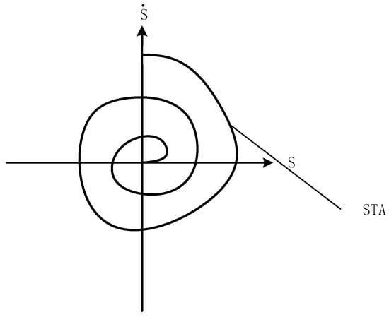
Figure 1.
Trajectory diagram of super-twisting algorithm.
The general form of the super-twisting algorithm:
where , are state variable estimates; is the observation error; is the observer gain parameter; is the perturbation term, and ,, is a Signum function.
It has been proven in reference [18] that if the perturbation term in Equation (5) is satisfied, i.e.,
where and are constants greater than 0, and , satisfy the following conditions:
Then the system is stable and converges in finite time.
Based on the STA mentioned above, in the permanent magnet synchronous motor control system, the state variables are selected as stator current, and ,, Equation (1) can be rewritten as:
where , and the super-twisting sliding mode observer is designed:
where and are estimated stator currents; and are the estimated error values of the current; ,.
Comparing Equation (9) with Equation (10), the perturbation term can be considered as:
where is a small perturbation in the system; .
When the observer is stable, the estimation error is on the sliding mode, which means that the estimate is close to the actual value, i.e., . The BEMF can then be directly estimated:
where , are estimated back electromotive force.
STA-SMO of convergence speed by the type of the linear decision, integral item associated with synovial buffeting suppression, usually taking larger value, used to suppress the chattering.
Figure 2 shows the block diagram of the overall STA-SMO structure.
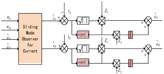
Figure 2.
Schematic diagram of super-twisting sliding mode observer.
3. Adaptive Improved Linear Super-Twisting SMO
3.1. Variable-Gain LSTA-SMO
The literature [27] propose a new super-twisting algorithm that combines the linear and the nonlinear correction terms, so that it inherits the best properties of both, described by the following differential inclusion:
where represents the state variables; represents the estimated variables; represents the errors between the estimated and measured variables; represents the constant gain that needs to be designed, and represents the disturbance term.
A Lyapunov proof that the theory holds is given in the literature [27].
Suppose that the perturbation terms of the system (13) are globally bounded by:
where the parameters are ,,,.
Equation (15) illustrates the range of values for the super-twisting algorithm parameter ; as long as the parameters of the observer are large enough, the system can converge to the sliding mode surface.
Included among these:
It is proven that the LSTA in Equation (13) satisfy the above stability conditions.
LSTA introduces two linear correction terms based on the traditional super-twisting sliding algorithm: , are based on the traditional super-twisting algorithm, as shown in Figure 3; the STA has exponential convergence, and the dynamic performance of the system modal reaching process is enhanced. This method not only preserves the strong immunity of the system at the origin, but also inhibits the strong disturbance far from the origin, which greatly enhances the anti-interference ability of the system.
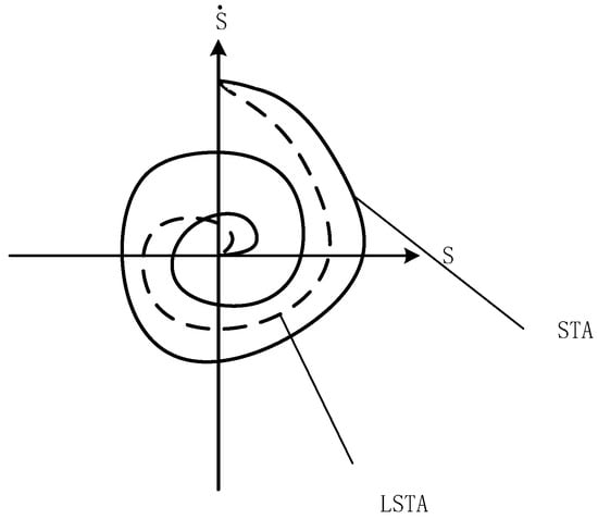
Figure 3.
Comparison of LSTA and STA diagrams.
Treating the current in the α-β coordinate system as a state variable, substituted and respectively, into the Equation (13). Here we design a LSTA-SMO-based observer for PMSM:
Eliminating the perturbation term , the current observer equation is as follows:
When the system stabilizes on the sliding surface, the estimated BEMF can be expressed as:
In addition, a variable sliding mode gain is proposed to meet the wide speed requirement. The parameters for this gain are designed as:
where are the adjustable coefficients; is a function of the motor speed; the expression is:
The parameter c is a constant value between 1/2 and 1.
3.2. Stability Analysis of VGLSTA-SMO
According to (14), when the super-twisting sliding mode observer is stabilized, there exist constants , = 1,2,3,4, such that the following equation holds:
From the above, it is clear that the global boundedness condition can be rewritten as:
Satisfying the stability condition, the combination of Equations (15) and (21) yields that a suitable is chosen such that the following equation holds:
The value of satisfies the system stability requirement, similarly.
By the same token, according to the stability condition of Equation (15), the value of should be satisfied.
as long as you choose a suitable , the following formula can be established:
By combining the Equations (14) and (24), along with the relationships , , we can find the Equation (27), that is:
In Equation (28), when the parameters , , , have been selected, the following expressions are given:
where and are constants, and an appropriate can be selected to ensure:
The above analysis shows that it is possible to choose suitable parameters , , so that the parameters , are varied with the actual speed of the motor, thus ensuring the stability of the system under the premise that the motor does not vibrate in the medium- and high-speed domain operation range.
3.3. Design of Adaptive BEMF Observer
The literature [26] proposes an adaptive control algorithm for the back electromotive force (EMF) of the five-phase permanent magnet synchronous motor. Based on this, this paper designs an adaptive adjustment method that is more robust and suitable for the medium- and high-speed domain for the three-phase permanent magnet synchronous motor. The algorithm is used to adaptively adjust the back electromotive force estimated by VGLSTA-SMO, and the formula is as follows:
where , are the estimated values of the reaction potential of the PMSM; is the estimated value of the rotor electrical angular velocity, and is the gain of the reaction potential adaptive observer.
Reverse potential estimation error equation for permanent magnet synchronous motor:
According to Lyapunov’s theory of stability, the Lyapunov function is:
where , and is a normal coefficient. So, the derivative of the Lyapunov function is:
where is a constant, and . Therefore,
Substituting the above equation into Equation (25) yields:
From the above equation, the Lyapunov function is positively determined. The designed inverse potential adaptive observer is stable when . Therefore, the inverse potential observer adaptive law is designed as:
3.4. Design of the Third-Order ESO
3.4.1. Conventional Phase-Locked Loop
After the inverse electromotive force information is observed, the current widely used data extraction method is the phase-locked loop (PLL) to extract the rotational speed and rotor position information. Its structure diagram is shown in Figure 4.
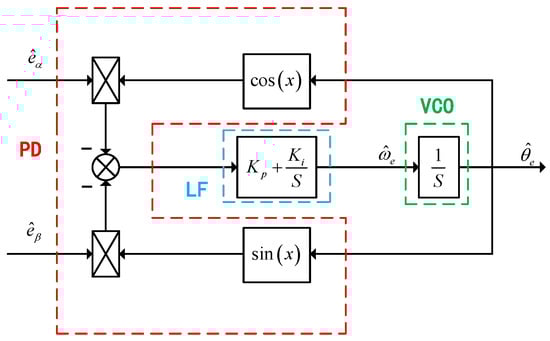
Figure 4.
Phase-Locked Loop Diagram.
In the Figure 4, and are the proportional and integral coefficients of the PI regulator, respectively. From Figure 5, the error signal of the conventional phase-locked loop can be obtained as:
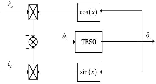
Figure 5.
TESO-PLL schematic diagram.
3.4.2. ESO-PLL Designs
Traditional PLL is a second-order system, and the state variables are electrical angle and speed. Therefore, the traditional PLL method based on the PI link actually assumes that the speed change is relatively slow, that is, the angular acceleration is about 0. Because of this, when the speed changes dynamically, there will be a poor dynamic effect.
In order to improve the estimation accuracy of motor speed and rotor position information, a third-order extended state observer (ESO) is constructed with rotor position error as a disturbance term, and the rotational speed and rotor position are estimated by the mechanical motion equation of the motor, Literature [28] uses this method in a six-phase PMSM. For the following forms of systems, an extended state observer is an idea of using a state observer to extend an unknown disturbance variable into a new state variable and using a special feedback mechanism to build a new observer to observe the extended state. Suppose that the numerical model of the controlled object is:
where is the unknown nonlinear function in the system; is the control quantity of the system; are state variables. Let be the disturbance and be the expanded state variable.
By selecting the state variables , Equation (36) is transformed into:
where , , , , .
The general expression for the third-order ESO is:
where is the observer ; is the observation of ; ,, and are intermediate variables; is the control quantity, and is the compensation factor.
ESO can accurately observe the characteristics of perturbations. The variable containing the rotor position and speed information is taken as the disturbance quantity, and the rotor position information is obtained by observing these variables. The block diagram of rotor position realization based on third-order ESO is shown in Figure 5.
Based on the relationship between rotational speed and rotor position in the rotor motion equation shown in Equation (4), the equation of state of the ESO with the rotor position angle as the main variable can be constructed, as shown in Equation (41). Its structure is shown in Figure 6.
where is the estimated electrical angular velocity; is the inertia; is the pole logarithm; is the load torque; is the error between the estimated and real rotor positions, and is the total disturbance of the system.
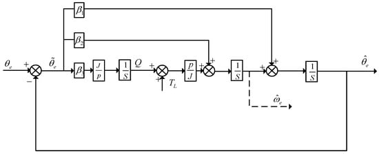
Figure 6.
TESO structure diagram.
Then, the closed-loop transfer function is:
where , , and are the coefficients of the third-order ESO, and wn is the bandwidth of the third-order ESO. In order to ensure the stability of the system, the characteristic equations can be overlapped at the same point and arranged in the left half of the S-plane. Adjustable parameter , based on bandwidth allocation method, makes the = 3, = 3, = . The reference range of wn is 1000–5000 rad/s, according to the actual adjustment effect (dynamic response speed, steady-state precision) and the reasonable choice of bandwidth.
In conclusion, the overall realization block diagram of the new SMO is shown in Figure 7. Estimates of stator currents and are obtained using a current observer, which is input to the VGLSTA-SMO module to obtain the inverse electromotive force. Finally, the rotor position information is obtained through the third-order ESO module.
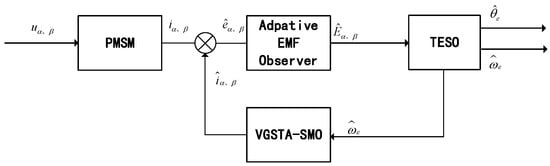
Figure 7.
Block diagram of the overall implementation of the improved adaptive SMO.
4. Simulation Study
The block diagram of the position of the sensorless vector control system of PMSM based on this method is shown in Figure 8. In order to verify the effect of the proposed sliding mode adaptive observer, the conventional sliding mode observer and the proposed sliding mode adaptive observer are compared and verified. Under the condition of speed of sudden change or load torque, the estimated effect of motor speed and rotor position and the experimental results are analyzed in detail. PMSM simulation parameters are as follows: ; ; ; .
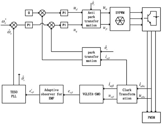
Figure 8.
Block diagram of permanent magnet synchronous motor control system based on VGLSTA-SMO.
In order to verify the accuracy and effectiveness of the three-phase permanent magnet synchronous motor control strategy proposed in this study, two sets of simulation experiments were conducted on Matlab to compare the performance of VGLSTA-SMO + TESO, LSTA-SMO + PLL, and traditional ST-SMO + PLL methods. Simulation comparing the performance of ST-SMO and LSTA-SMO. The LSTA-SMO proved to be more effective. The motor was started with no load, set to 4000 rpm, and after 1 s, the speed dropped to 1000 rpm.
As shown in Figure 9, Figure 10, Figure 11 and Figure 12, when the speed is 4000 r/min, the maximum speed error of fixed gain STA-SMO is 53.6 rpm, and the rotor position error is basically stable at 1.14 rad. The maximum speed error of fixed gain LSTA-SMO is 14.1 rpm, and the rotor error is basically stable at 1.07 rad. When the speed is 1000 r/min, the maximum speed error of fixed gain STA-SMO is 53.6 rpm, and the rotor position error is basically stable at 1.14 rad. The maximum speed error of fixed gain LSTA-SMO is 14.1 rpm, and the rotor error is basically stable at 1.14 rad. At 1000 rpm, the fixed gain STA-SMO has a maximum speed error of 73.5 rpm and a rotor position error of 1.65 rad. The fixed gain LSTA-SMO has a maximum speed error of 12.3 rpm and a rotor error of 1.42 rad. The LSTA-SMO has better performance in the medium-to-high-speed area. Table 1 summarizes the improvements of the two methods at 1000 rpm compared to 4000 rpm.
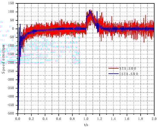
Figure 9.
Comparison of rotational speed errors between LSTA and STA observations.
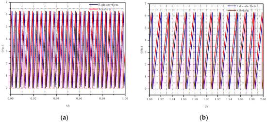
Figure 10.
STA-SMO estimated and actual rotor position waveforms under different speeds: (a) 4000 rpm; (b) 1000 rpm.
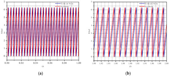
Figure 11.
LSTA-SMO estimated and actual rotor position waveforms under different speeds: (a) 4000 rpm; (b) 1000 rpm.
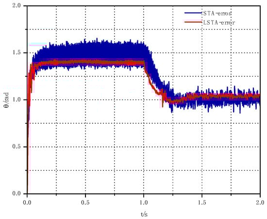
Figure 12.
Comparison of LSTA-SMO and STA-SMO Observation Angle Errors.

Table 1.
Performance Comparison Between Different Observers.
In order to verify the adaptive super-twisting sliding algorithm, LSTA-SMO under the action of fixed synovial coefficient is analyzed. Among them, the synovial coefficient of LSTA-SMO under the action of fixed synovial coefficient is set to two different values, with one being smaller, where Z1 = 250, and Z2 = 450. The other set is placed to the larger Z1 = 500 and Z2 = 900. The speed is set to 6000 rpm.
When the motor runs stably with no load at 10,000 rpm, it can be seen from Figure 13 and Figure 14 that the maximum speed estimation error of LSTA-SMO is 89 rpm, and the position estimation error is about 0.19 rad under the action of a small fixed sliding mode coefficient. The maximum speed estimation error of LSTA-SMO is 82 rpm, and the position estimation error is about 0.17 rad under the action of a large fixed sliding mode coefficient.
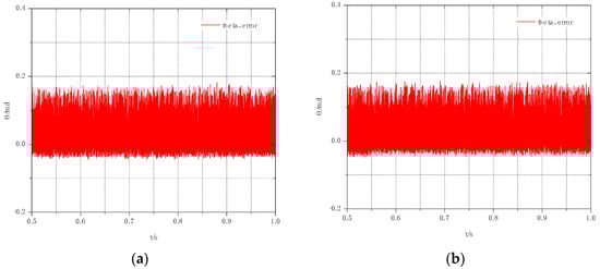
Figure 13.
Comparison of LSTA-SMO observation angle errors for different slip film coefficients: (a) LSTA-SMO observation angle error when Z1 = 250, and Z2 = 500; (b) LSTA-SMO observation angle error when Z1 = 450, and Z2 = 900.
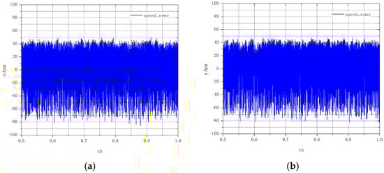
Figure 14.
Comparison of LSTA-SMO observation speed errors for different slip film coefficients: (a) LSTA-SMO observation angle error when Z = 250, and Z2 = 500; (b) LSTA-SMO observation angle error when Z1 = 450, and Z2 = 900.
In order to further verify the effectiveness of the proposed algorithm, the second set of experiments involves setting the PMSM with VGLSTA-SMO to rotate at 5000 rpm when unloaded and boosting it to 10,000 rpm at 1 s. Subsequently, after reaching the given speed of 10,000 rpm, the torque is adjusted by adding or subtracting 2 N·m. The structure of the Matlab simulation is shown in Figure 15.
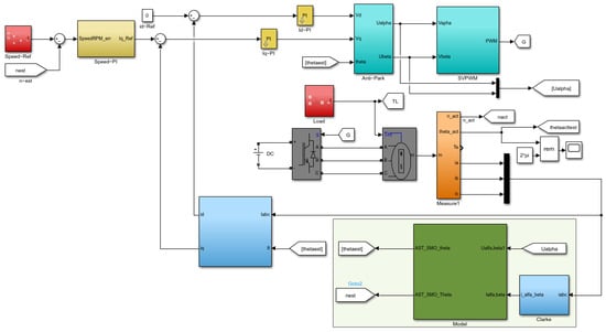
Figure 15.
Matlab simulation structure of VGLSTA-SMO.
As can be seen from Figure 16, the sliding mode gain gradually increases with the increase in estimated speed, thereby reducing the phenomenon of buffeting caused by excessive sliding mode gain at low speed. Meanwhile, a sufficiently large sliding mode gain at high speed can ensure the stability of VGLST-SMO.
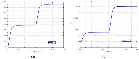
Figure 16.
Proposed VGLSTA-SMO sliding mode gain variation (a) Z1 value; (b) Z2 value.
From Figure 17, it can be observed that there is a static difference between the rotational speed obtained from the estimation of the sliding mode observer using constant sliding mode gain and the rotational speed given, Figure 17a shows that the LSTA-SMO with fixed slip film gain can achieve 5000 rpm. In contrast, Figure 17b reveals a static difference of 1600 rpm in the rotational speed when the target rotational speed is set to 10,000 rpm.
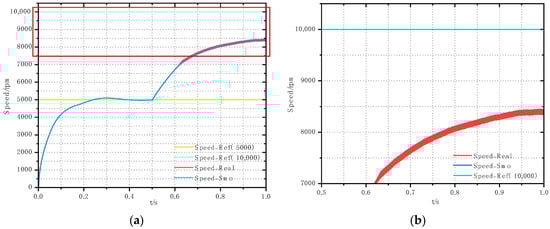
Figure 17.
Plot of rotational speed observations under constant sliding mode gain control: (a) comparison of observed RPM, actual RPM, and given RPM; (b) local enlargement.
Figure 18 displays the rotational speed observation results acquired using the sliding mode observer with adaptive variable sliding mode gain, as defined in Equation (13). It is evident that the static difference in rotational speed has been markedly reduced, which isconsistent with the theoretical analysis. Additionally, the effectiveness of the rotational speed loop control has been enhanced, effectively improving the FOC control efficiency.
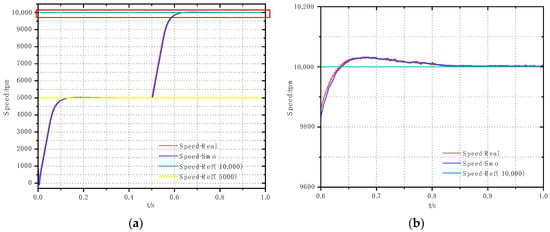
Figure 18.
Plot of rotational speed observations under adaptive variable smooth mode gain control: (a) comparison of observed RPM, actual RPM, and given RPM; (b) local enlargement.
Figure 19 illustrates that the speed jitter is smaller when the VGLSTA-SMO utilizes Equation (13). Furthermore, Figure 20 demonstrates that with the addition of load torque, LSTA-SMO is unable to recover the given speed promptly, whereas VGLSTA-SMO recovers to the target speed within 0.41 s. In the case of reduced load torque, VGLSTA-SMO again performs well, recovering to the given speed within 0.3 s.
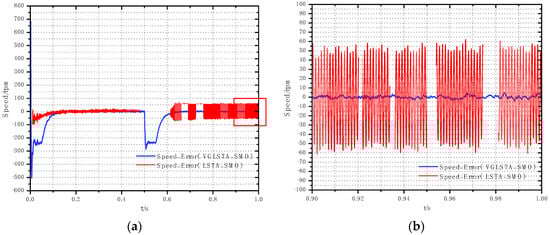
Figure 19.
Plot of motor speed error observed for LSTA-SMO with constant slip film gain vs. VGLSTA-SMO with variable slip film gain: (a) Speed Error Comparison; (b) local enlargement.
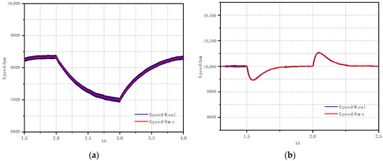
Figure 20.
Plot of actual speed observed rotational speed for a given speed of 10,000 rpm with variations due to load torque: (a) speed observed under adaptive variable smoothing mode gain VGLSTA-SMO control; (b) speed observed under constant gain LSTA-SMO control.
Figure 21 and Figure 22 present a comparison of rotor position angle observations before and after applying the inverse potential adaptive optimization. It is evident from these figures that the error in the rotor position angle signal, as obtained by the sliding mode observer, is significantly reduced after employing the inverse potential adaptive optimization described in Equation (25). Furthermore, as shown in Figure 23, the steady-state error is reduced from 1.74° to 0.0005°, indicating that the inverse potential adaptive optimization can effectively mitigate the medium- and phase lag phenomena that occur during high-speed operation, which is in line with the theoretical analysis.
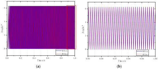
Figure 21.
Comparison of LSTA-SMO observation speed errors for different slip film coefficients: (a) comparison of observed and actual values of position angle; (b) local enlargement.
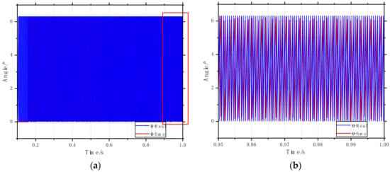
Figure 22.
Constant Slip Coefficient LSTA-SMO Position Angle Observations: (a) comparison of observed and actual values of position angle; (b) local enlargement.
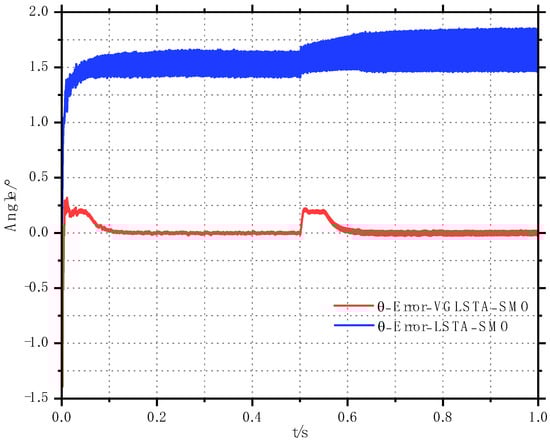
Figure 23.
Comparison of motor Position Angle Error Observation of LSTA-SMO and VGLSTA-SMO.
Table 2 summarizes the improvements of the LSTA-SMO and VGLSTA-SMO methods at 5000 rpm compared to 10,000 rpm, and summarizes the time taken for speed recovery during load and unload. From the above simulation results, it can be seen that VGLSTA-SMO can still maintain an accurate estimation of speed and rotor position when loading, and the improved sliding mode position sensorless control system proposed in this paper is feasible.
Table 2.
Performance Comparison Between Different Observers.
5. Conclusions
In this work, a new sensorless control method of PMSM is presented, which effectively solves the problem of high-frequency buffering in the estimation of back electromotive force, rotor position, and motor speed in the high-speed domain of the traditional method. Based on the super sliding mode observer, the linear term of observation error is adopted, resulting in the dynamic performance and anti-interference ability of the system mode approaching the sliding die surface being improved due to the addition of an adaptive parameter adjustment strategy. In view of the high harmonic content of the estimated back electromotive force, the adaptive adjustment strategy can solve the problem of harmonic interference estimation of position and velocity accuracy of the traditional method. Finally, the extended state observer can track the actual rotor position and actual speed well. The proposed method is analyzed and verified by Matlab simulation platform data, and the proposed method has a remarkable effect on reducing high-frequency jitter compared with the traditional super-twisting sliding mode observer.
This work can be applied to sensing and localizing redundancy when electric vehicle sensors fail, realizing complementary sensing hardware capabilities, and strengthening sensing capabilities. However, permanent magnet synchronous motors for electric vehicles are often in complex operating conditions, so future research directions should be verified on physical objects, and external influences should be added.
Author Contributions
Conceptualization, L.S.; formal analysis, L.S. and P.L.; data curation, L.S. and M.L.; writing—review and editing, L.S. and P.L. All authors have read and agreed to the published version of the manuscript.
Funding
This work is supported by the Science and Technology Research Project of the Jilin Provincial Department of Education (JJKH20210046KJ).
Data Availability Statement
The data presented in this study are available on request from the corresponding authors.
Conflicts of Interest
The authors declare no conflicts of interest.
References
- Zuo, Y.; Lai, C.; Iyer, K.L.V. A Review of Sliding Mode Observer Based Sensorless Control Methods for PMSM Drive. IEEE Trans. Power Electron. 2023, 38, 11352–11367. [Google Scholar] [CrossRef]
- Xiong, Y.; Wang, A.; Zhang, T. Sensor-less complex system control of pmsm based on improved smo. In Proceedings of the 2021 6th International Conference on Automation, Control and Robotics Engineering (CACRE), Dalian, China, 15–17 July 2021; IEEE: Piscataway, NJ, USA, 2021; pp. 228–232. [Google Scholar]
- Liu, G.; Zhang, H.; Song, X. Position-estimation deviation-suppression technology of PMSM combining phase self-compensation SMO and feed-forward PLL. IEEE J. Emerg. Sel. Top. Power Electron. 2020, 9, 335–344. [Google Scholar] [CrossRef]
- Zhu, H.; Xiao, X.; Li, Y. A simplified high frequency injection method for PMSM sensorless control. In Proceedings of the 2009 IEEE 6th International Power Electronics and Motion Control Conference, Wuhan, China, 17–20 May 2009; IEEE: Piscataway, NJ, USA, 2009; pp. 401–405. [Google Scholar]
- Kesavan, P.; Karthikeyan, A. Electromagnetic Torque-Based Model Reference Adaptive System Speed Estimator for Sensorless Surface Mount Permanent Magnet Synchronous Motor Drive. IEEE Trans. Ind. Electron. 2020, 67, 5936–5947. [Google Scholar]
- Zhao, X.; Wang, C.; Duan, W.; Jiang, J. Research on sensorless control system of low speed and high power PMSM based on improved high frequency signal injection. Energy Rep. 2021, 7, 499–504. [Google Scholar] [CrossRef]
- Jiang, Y.; Cheng, M. An improved initial rotor position estimation method using high-frequency pulsating voltage injection for PMSM. Def. Technol. 2023, 33, 19–29. [Google Scholar] [CrossRef]
- Lu, Q.; Wang, Y.; Mo, L.; Zhang, T. Pulsating High Frequency Voltage Injection Strategy for Sensorless Permanent Magnet Synchronous Motor Drives. IEEE Trans. Appl. Supercond. 2021, 38, 5204204. [Google Scholar] [CrossRef]
- Dhaouadi, R.; Mohan, N.; Norum, L. Design and implementation of an extended Kalman filter for the state estimation of a permanent magnet synchronous motor. IEEE Trans. Power Electron. 1991, 6, 491–497. [Google Scholar] [CrossRef]
- Ma, Z.; Zhang, X. FPGA-based sensorless control for PMSM drives using the stator/rotor frame extended Kalman filter. In Proceedings of the 2018 Chinese Control and Decision Conference (CCDC), Shenyang, China, 9–11 June 2018; IEEE: Piscataway, NJ, USA, 2018; pp. 102–107. [Google Scholar]
- Liang, D.; Li, J.; Qu, R.; Kong, W. Adaptive second-order sliding-mode observer for PMSM sensorless control considering VSI nonlinearity. IEEE Trans. Power Electron. 2017, 33, 8994–9004. [Google Scholar] [CrossRef]
- Kang, K.L.; Kim, J.M.; Hwang, K.B.; Kim, K.H. Sensorless control of PMSM in high-speed range with iterative sliding mode observer. In Proceedings of the Nineteenth Annual IEEE Applied Power Electronics Conference and Exposition, APEC’04, Anaheim, CA, USA, 22–26 February 2004; IEEE: Piscataway, NJ, USA, 2004; Volume 2, pp. 1111–1116. [Google Scholar]
- Moreno, J.A.; Osorio, M. Strict Lyapunov functions for the super-twisting algorithm. IEEE Trans. Autom. Control 2012, 57, 1035–1040. [Google Scholar] [CrossRef]
- Wang, T.; Hu, G.; Yu, Q. An improved sensorless control scheme for PMSM with online parameter estimation. In Proceedings of the 2021 IEEE 16th Conference on Industrial Electronics and Applications (ICIEA), Chengdu, China, 1–4 August 2021; IEEE: Piscataway, NJ, USA, 2021; pp. 239–244. [Google Scholar]
- Zhao, K.; Leng, A.; She, J.; Zhang, C.; He, J.; Li, T. Closed-loop Torque Control for Permanent Magnet Synchronous Motor by Super-Twisting Algorithm Based Sliding-Mode Observer Considering Demagnetization. In Proceedings of the 2020 IEEE 29th International Symposium on Industrial Electronics (ISIE), Delft, The Netherlands, 17–19 June 2020; IEEE: Piscataway, NJ, USA, 2020; pp. 1566–1571. [Google Scholar]
- Huang, J.; Mao, J.; Dong, X.; Mei, K.; Madonski, R.; Zhang, C. Cascaded Generalized Super-Twisting Observer Design for Sensorless PMSM Drives. IEEE Trans. Circuits Syst. II Express Briefs 2024, 71, 331–335. [Google Scholar] [CrossRef]
- Liang, D.; Li, J.; Qu, R. Super-twisting algorithm based sliding mode observer for wide-speed range PMSM sensorless control considering VSI nonlinearity. In Proceedings of the 2017 IEEE International Electric Machines and Drives Conference (IEMDC), Miami, FL, USA, 21–24 May 2017; pp. 1–7. [Google Scholar]
- Zhan, Y.; Guan, J.; Zhao, Y. An adaptive second-order sliding-mode observer for permanent magnet synchronous motor with an improved phase-locked loop structure considering speed reverse. Trans. Inst. Meas. Control 2020, 42, 1008–1021. [Google Scholar] [CrossRef]
- Wang, D.; Liu, X. Sensorless Control of PMSM with Improved Adaptive Super-Twisting Sliding Mode Observer and IST-QSG. IEEE Trans. Transp. Electrif. 2024. early access. [Google Scholar] [CrossRef]
- Liu, W.; Luo, B.; Yang, Y.; Niu, H.; Zhang, X.; Zhou, Y.; Zeng, C. An Adaptive-Gain Sliding Mode Observer with Precise Compensation for Sensorless Control of PMSM. Energies 2023, 16, 7968. [Google Scholar] [CrossRef]
- Tian, Z.; Shen, K. Research on Sensorless Control System of PMSM Based on Adaptive Fuzzy Sliding Mode Observer. J. Phys. Conf. Ser. 2020, 1576, 012050. [Google Scholar] [CrossRef]
- Yao, G.; Wang, X.; Wang, Z.; Xiao, Y. Senseless Control of Permanent Magnet Synchronous Motors Based on New Fuzzy Adaptive Sliding Mode Observer. Electronics 2023, 12, 3266. [Google Scholar] [CrossRef]
- Wang, H.; Zhang, G.; Liu, X. Sensorless Control of Surface-Mount Permanent-Magnet Synchronous Motors Based on an Adaptive Super-Twisting Sliding Mode Observer. Mathematics 2024, 12, 2029. [Google Scholar] [CrossRef]
- Yang, J.W.; Dou, M.F.; Zhao, D.D.; Yan, L.M. Adaptive sliding mode observer-based position sensorless control of five-phase permanent magnet synchronous motor. J. Northwestern Polytech. Univ. 2016, 34, 1057–1064. [Google Scholar]
- Hoai, H.-K.; Chen, S.-C.; Than, H. Realization of the Sensorless Permanent Magnet Synchronous Motor Drive Control System with an Intelligent Controller. Electronics 2020, 9, 365. [Google Scholar] [CrossRef]
- Hoai, H.-K.; Chen, S.-C.; Chang, C.-F. Realization of the Neural Fuzzy Controller for the Sensorless PMSM Drive Control System. Electronics 2020, 9, 1371. [Google Scholar] [CrossRef]
- Moreno, J.A.; Osorio, M.A. A Lyapunov approach to second-order sliding mode controllers and observers. In Proceedings of the 2008 47th IEEE Conference on Decision and Control, Cancun, Mexico, 9–11 December 2008; IEEE: Piscataway, NJ, USA, 2008. [Google Scholar]
- Gao, H.; Zhang, G.; Wang, W.; Liu, X. Research on an Improved Sliding Mode Sensorless Six-Phase PMSM Control Strategy Based on ESO. Electronics 2021, 10, 1292. [Google Scholar] [CrossRef]
Disclaimer/Publisher’s Note: The statements, opinions and data contained in all publications are solely those of the individual author(s) and contributor(s) and not of MDPI and/or the editor(s). MDPI and/or the editor(s) disclaim responsibility for any injury to people or property resulting from any ideas, methods, instructions or products referred to in the content. |
© 2024 by the authors. Licensee MDPI, Basel, Switzerland. This article is an open access article distributed under the terms and conditions of the Creative Commons Attribution (CC BY) license (https://creativecommons.org/licenses/by/4.0/).