Abstract
Hydrogen is gaining prominence as a clean energy vector, yet its extreme flammability demands robust detection solutions for industrial safety. In this study, we present the development and experimental validation of a microwave hydrogen gas sensor based on a patch-type microstrip antenna with a silver sensing element. The device operates at 5.99 GHz and was tested under controlled environmental conditions (humidity: 20 ± 0.4%, temperature: 27 ± 0.2 °C). Hydrogen exposure induces measurable shifts in the antenna’s resonant frequency due to dielectric modulation of the silver layer. The sensor exhibited a linear sensitivity of 3 kHz/ppm in the 310–600 ppm concentration range, with a residual standard deviation of 31.1 kHz and a calculated limit of detection (LOD) of approximately 31 ppm. The reflection coefficient remained below −10 dB throughout, confirming that the antenna maintains functional RF performance during sensing. These results demonstrate the sensor’s dual functionality for gas detection and communication, offering a compact and scalable platform for hydrogen safety monitoring.
1. Introduction
Hydrogen is one of the primary methods of energy transportation today, playing a crucial role in global strategies aimed at reducing greenhouse gas emissions [1,2]. In the industrial sector, hydrogen’s use is vital for supporting alternative carbon fuel processes, particularly in industries such as cement production, steel manufacturing, natural gas refining, and long-distance heavy transport [3,4]. Currently, many hydrogen hubs are being constructed globally, and this emerging industry is anticipated to grow rapidly, though it presents several uncertainties regarding safety in handling.
Unlike other gases, hydrogen features a broad range of flammability, a fast flame propagation speed, and a high diffusion rate [5]. Additionally, safety challenges in this sector are compounded by the fact that hydrogen is colorless and odorless; leaks can occur without detection [6], and flames are nearly invisible during the day [7], illustrating a significant potential for emerging risks. The classification of emerging risks pertains to new or evolving threats in systems involving human operators, technological components, and organizational policies, which are recognized as complex adaptive systems (CAS) [8].
The search for greater safety in the handling of hydrogen gas is constant in industry. For this reason, many sensors are used to predict accidents. Gas sensors are fundamental for gas safety and handling in various industries, including the detection of harmful chemical vapors, environmental monitoring, industrial and agricultural production, medical diagnosis, and military and public safety [9]. The study and development of new sensors are indispensable in hydrogen industries and directly impact safety, health, and environmental risks [10,11,12].
Microwave gas sensors operate based on the dielectric interaction between a sensitive antenna material and the gas being detected under microwave frequency excitation [13]. Microwave gas sensing antennas are assembled with propagative structures specifically designed for operation within the target spectrum, where the structures absorb gas through the antenna’s sensing element, modifying its dielectric properties for sensory response [14]. Many types of microwave structures have been explored, including gas sensors, microwave resonators [15,16,17], metamaterials [18,19], couplers [20], and patch antennas [9,21].
The patch antenna is a versatile type of microstrip antenna, providing significant advantages in gas sensing due to its adaptability to various geometries [16,17,18,19,20,21,22,23,24,25,26,27,28,29,30]. Table 1 presents some key sensing studies utilizing patch-type microstrip antennas, highlighting a diverse range of gas sensing applications, operating frequencies, and substrates used.

Table 1.
Sensing studies using microstrip antennas.
Many chemical elements serve as sensing components in patch antennas across various industrial applications. One element that stands out is silver (Ag), known for its excellent electrical conductivity, high corrosion resistance, and low reactivity. Silver has been utilized as a sensing element in microstrip antennas for gas detection. Nascimento et al. [21] presented a patch antenna equipped with a silver sensor element for detecting oxygen gas in their study. This antenna demonstrated a sensitivity of 230 kHz/%O2 and operates at a frequency near 8.2 GHz. Studies show that silver (Ag) has a good chemical affinity for hydrogen. Experimental surface studies have shown that hydrogen atoms can chemisorb on low-index silver surfaces such as Ag(110) and Ag(111), inducing measurable changes in work function and vibrational properties [31,32,33]. For example, Sprunger and Plummer [31] demonstrated that atomic hydrogen adsorbs Ag(110), altering the surface’s electronic structure and inducing structural rearrangements. Geunseop Lee et al. [32] reported similar findings on Ag(111), observing a change in the work function of about 0.32 eV and distinct vibrational modes using high-resolution electron energy loss spectroscopy (HREELS). Pez and Steyert [33] further confirmed the presence of adsorbed hydrogen species on silver surfaces at cryogenic temperatures, with desorption energies indicative of strong surface binding.
This work presents the numerical simulation and development of a hydrogen gas sensor using a patch-type microstrip antenna with a silver film serving as the sensory element. The device was specifically designed for the detection of hydrogen gas (H2) under controlled temperature and humidity conditions for application in highly critical security systems, where the variables have the same studied control. The novelty of this work lies in the use of a microstrip patch antenna with a silver (Ag) sensing element as a hydrogen detection platform operating in the microwave range. The sensor demonstrates a linear sensitivity based on the frequency shift of the reflection parameter S11. Unlike traditional approaches such as field-effect transistor (FET)-based sensors or chemiresistors, which often require dedicated readout electronics and may suffer from drift under environmental variations, microwave sensors offer a passive, contactless solution that can be easily integrated into wireless networks. This approach enables real-time monitoring with greater immunity to noise and electromagnetic interference and is suitable for operation under controlled temperature and humidity conditions, as shown in this study.
FET and chemiresistor-based gas sensors are widely used due to their high sensitivity, but they often exhibit slow response times, long-term instability, and cross-sensitivity to other gases [11,12]. In contrast, microwave-based gas sensors, which rely on dielectric property variations, provide higher stability, faster response, and can operate without direct contact with the target gas. These advantages make microwave sensing particularly attractive for industrial and safety-critical environments.
Regarding practical applications, hydrogen concentrations below 1000 ppm are relevant for early leak detection in industrial and safety systems since levels above 4000 ppm (or 4% vol) pose an explosion hazard under standard atmospheric conditions [34]. The proposed sensor was tested in a range from 0 to 600 ppm, which adequately covers the early warning thresholds commonly used in hydrogen monitoring and ventilation control systems. This makes it suitable for critical applications such as storage facilities, hydrogen-powered vehicles, and fuel cell systems.
2. Materials and Methods
The microstrip antenna is an advanced and compact device typically utilized in various communication systems [35]. In this case, it was constructed using a small phenolite plate as the substrate material. A crucial component of the antenna is the copper radiator element, also known as the patch, which plays a vital role in transmitting and receiving signals. Additionally, a sensor element made from silver film has been integrated into the design to enhance performance. The power supply for the antenna is provided via an SMA (SubMiniature version A) connector, facilitating a reliable connection to external devices.
Before the physical manufacturing of the antenna, numerical simulations were carried out using the High-Frequency Structure Simulator (HFSS) software version 13.0. This phase was essential for optimizing various aspects of the antenna, including its geometry, dimensions, and impedance matching with the antenna’s power supply. Proper impedance matching is crucial to minimize signal reflections and maximize power delivery.
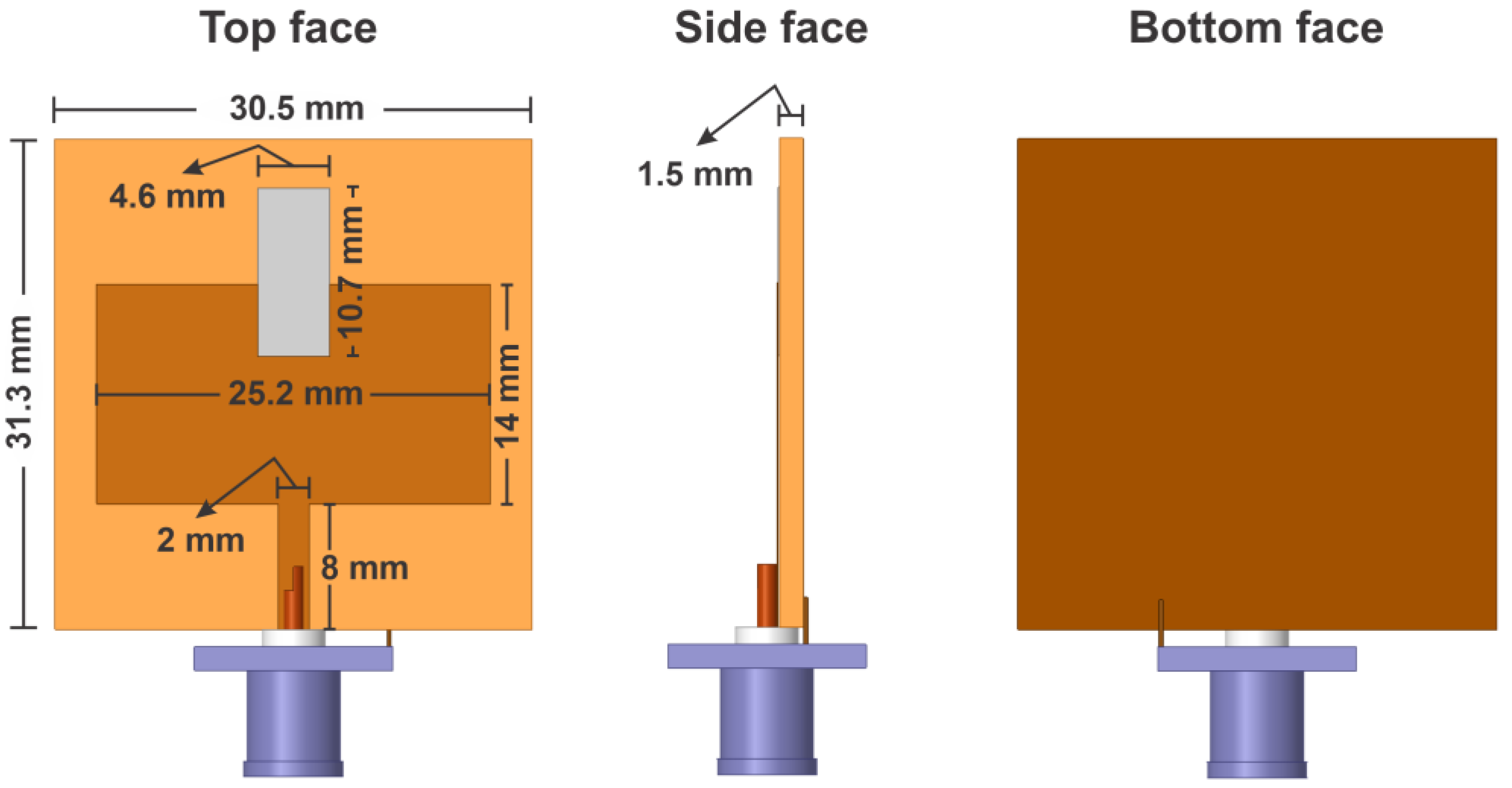
Figure 1 presents a detailed design of the microstrip antenna, depicting the specific dimensions utilized in the numerical simulation, thereby illustrating how the theoretical work translates into practical application.
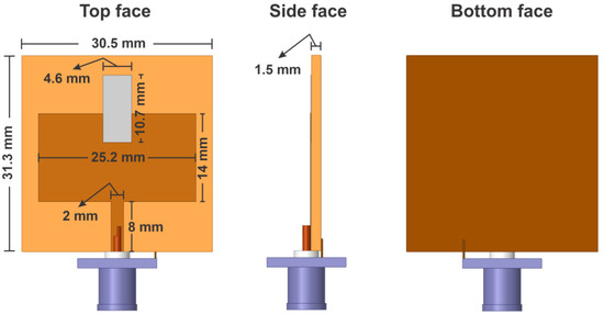
Figure 1.
Design of the microstrip antenna.
On the top face of the structure, the phenolic substrate is depicted in orange, the copper tape forming the patch is shown in brown, and the silver-based sensing element appears in light gray. The bottom face, which functions as the antenna’s ground plane, is entirely covered with copper, also represented in brown. In the lower section of the illustration, the SMA connector is highlighted in blue, linking the power probe (shown in dark brown) to the antenna structure. Additionally, a soldered copper wire on the bottom face ensures electrical continuity between the ground plane and the metallic sleeve of the SMA power connector. The silver sensing element was manually deposited on the phenolic substrate using a fine brush, forming a uniform conductive layer with an average thickness of approximately 0.1 mm. The paint used was a commercially available silver-based conductive ink.
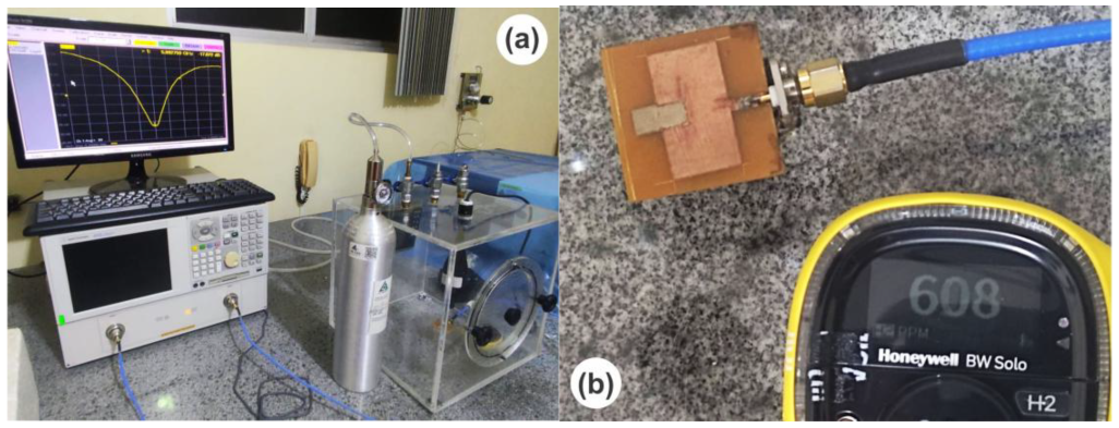
The microstrip antenna prototype was meticulously developed in accordance with simulated dimensions, and hydrogen gas sensing experiments were conducted using the configuration shown in the images presented in Figure 2.
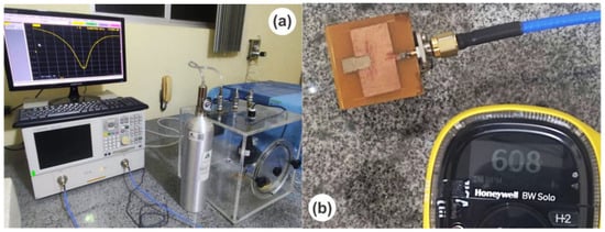
Figure 2.
(a) Equipment for sensing hydrogen gas (H2); (b) patch antenna and commercial sensor inside the glovebox.
Figure 2a presents a photo of the equipment used for sensing hydrogen gas, specifically utilizing a patch antenna that features a silver sensing element. This image highlights an Agilent network analyzer (document number: N5230C), which plays a crucial role in acquiring experimental curves of various reflection parameters, notably S11. The reflection coefficient S11 is given by Equation (1):
where S11 is the reflection coefficient indicating the ratio of reflected power to incident power, Zin is the antenna input impedance, and Z0 is the medium impedance (50 ohms). The reflection coefficient can also be expressed in terms of dB for ease of interpretation:
From the antenna input impedance, it is possible to measure the real (Z′) and imaginary (Z”) impedances associated with the system and given by the following equation:
where Z′ is the real part (resistive) and Z” is the imaginary part (reactive).
Figure 2a also shows a hydrogen cylinder connected to a transparent acrylic glovebox, which is essential for conducting the experiments in a controlled environment.
Moving to Figure 2b, we find a view of the interior of the glovebox, where several key components are visible. These include the patch antenna prototype alongside a commercial hydrogen sensor produced by Honeywell (model: BW) and a reference soil sample utilized for measurement purposes.
Before performing hydrogen sensitivity measurements, it is important to note that the floor of the glovebox was filled with silica material. This was performed strategically to minimize moisture levels, which could interfere with the measurements. All sensing measurements were carried out under precisely controlled humidity conditions maintained at around 20% (±0.4%) and a temperature kept near 27 °C (±0.2 °C).
The sensing measurements were executed by introducing hydrogen gas into the glovebox environment. The injection of hydrogen gas was performed in stages, and after each injection, the system was kept closed and undisturbed for a waiting period of 10 min before any measurements were performed. This interval was chosen to allow passive diffusion and homogeneous distribution of the gas throughout the glove box volume. The patch antenna parameter S11 experiences variations in its readings when hydrogen gas enters the glovebox and interacts with the antenna’s sensing element. The gas injection is meticulously performed, and the concentration is quantified in parts per million (ppm) using the commercial hydrogen sensor. To ensure accurate comparison, the minimum points of the S11 parameter curve are meticulously collected and compared against the results obtained from the commercial sensor to verify linearity.
The sensing tests spanned a range from 0 to 600 ppm of hydrogen within the glovebox. Each measurement was recorded with 5 min intervals between them, allowing time for the gas distribution to stabilize within the glovebox, thereby ensuring a homogeneous gas environment for accurate measurement.
3. Results
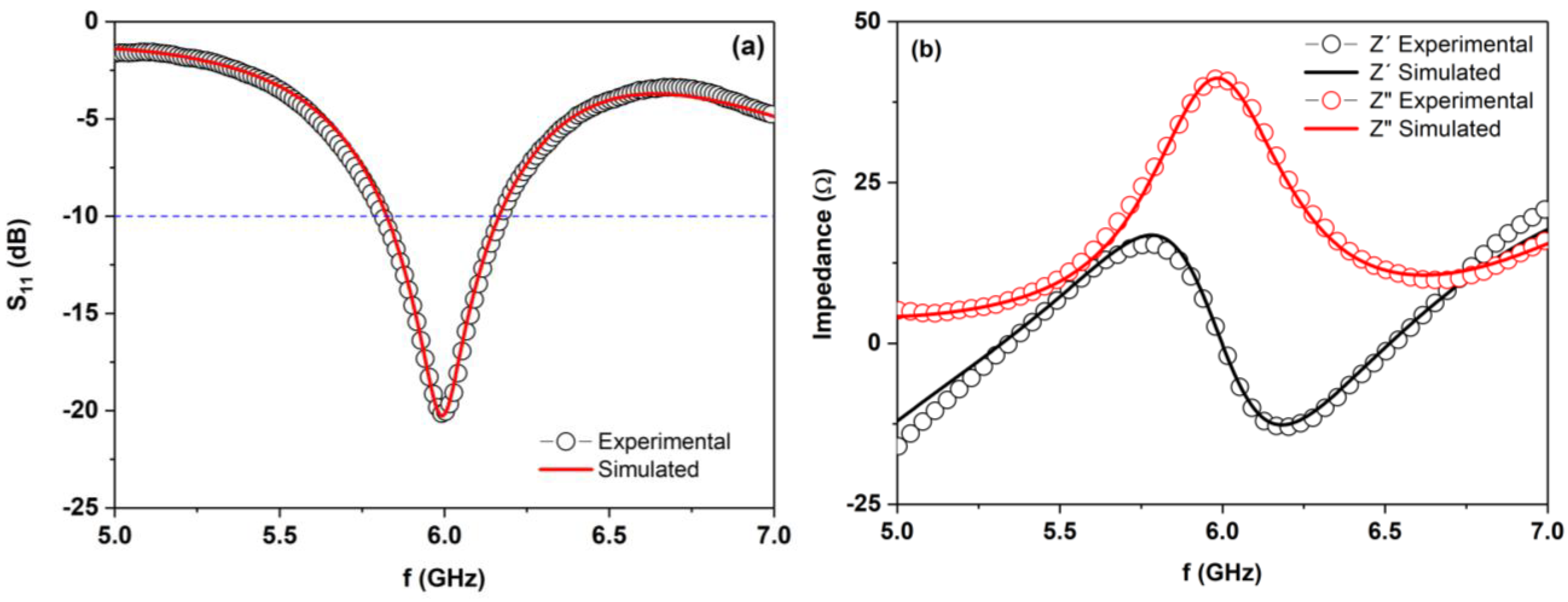
The numerical study of the patch antenna, which incorporates a silver sensory element, was conducted using Ansys HFSS software. This comprehensive analysis revealed that the simulation model was suitable for accurately representing the antenna’s behavior. In particular, the results demonstrated a notable correlation between experimental measurements and simulated predictions of the reflection parameter, known as S11. As illustrated in Figure 3a, the curves plotted for both the experimental and simulated data show a high level of agreement in their profiles. This concordance not only supports the reliability of the numerical simulation but also affirms the effectiveness of the simulation model in capturing the antenna’s performance characteristics.
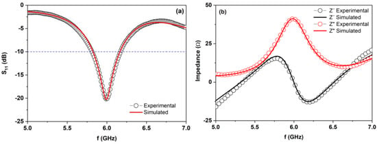
Figure 3.
(a) Simulated and experimental parameter S11; (b) real and imaginary parts of the experimental and simulated impedances.
In addition to the reflection parameter (S11), the real and imaginary parts of the experimental and simulated impedances were compared. Figure 3b demonstrates a strong agreement between the impedance profiles, clearly indicating the validity of the simulation conducted. The minimum reflection coefficient S11 is required to be below −10 dB (blue line in Figure 3a) to control interference and improve the signal-to-noise ratio.
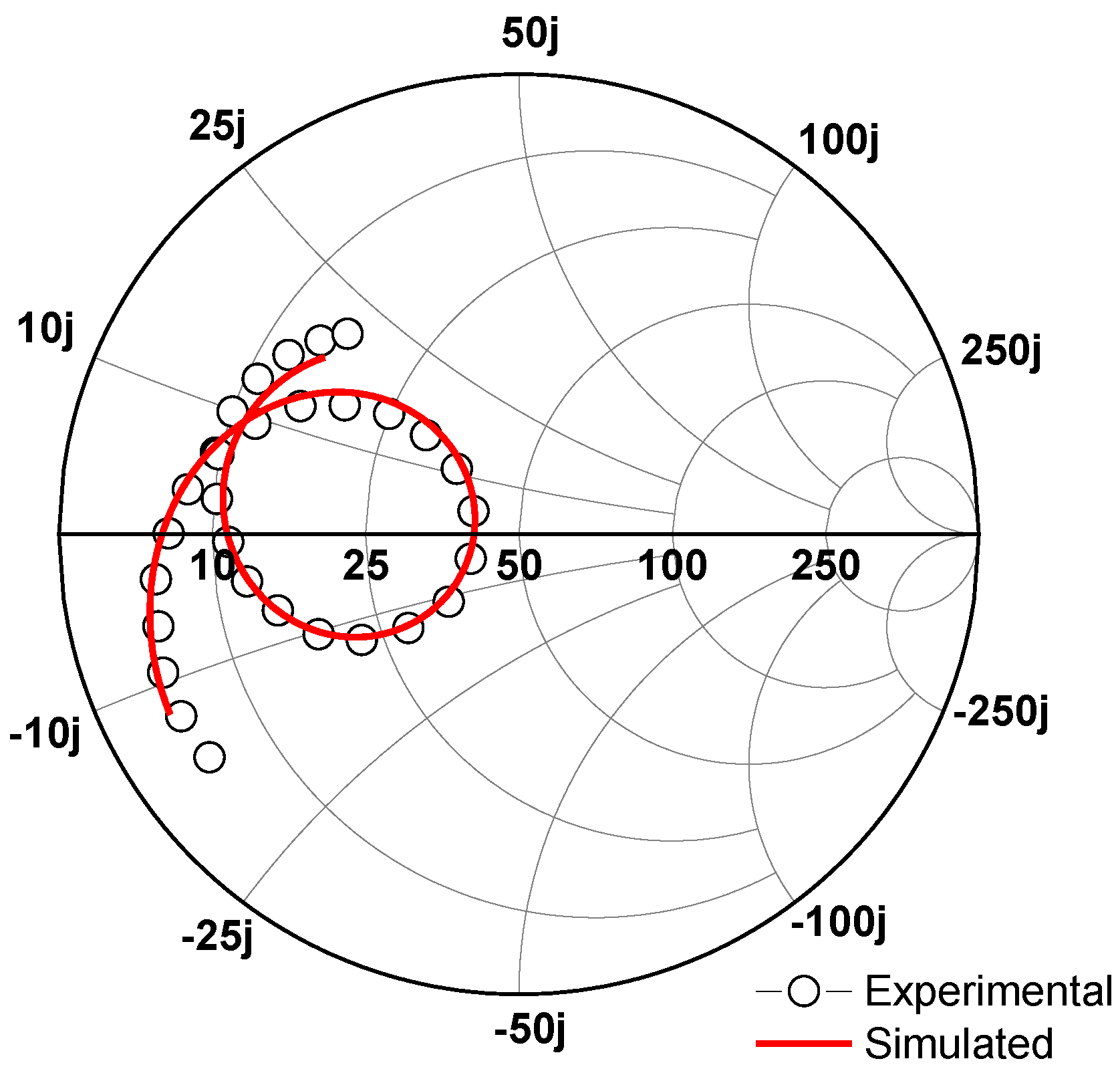
Figure 4 illustrates the Smith chart for both the experimental and simulated data of the patch antenna, providing a comprehensive visual representation of its impedance characteristics. The Smith chart, a tool widely used in RF engineering, displays how the impedance of the antenna varies with frequency. This scenario shows a notable alignment between the experimental and simulated impedances, which suggests that the model used for simulation accurately reflects the antenna’s real-world performance.
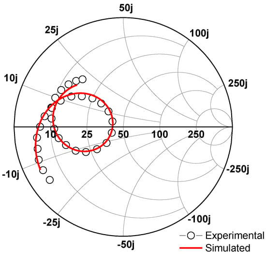
Figure 4.
Experimental and simulated Smith chart.
One key observation from the Smith chart is that the curve loop is located on the left side of the chart, corresponding to lower resistance values. This positioning implies that the antenna operates at lower resistive energies, which is often desirable for achieving better performance in wireless communication systems.
Additionally, the curve loop occupies the upper portion of the graph, indicating that the antenna presents predominantly positive reactance values. High positive reactance typically signifies that the antenna exhibits inductive behavior, meaning it stores energy in a magnetic field and has a tendency to oppose changes in current. In practical terms, this inductive characteristic can impact the antenna’s matching to transmission lines and overall efficiency, which is crucial for optimizing signal transmission. Hence, the data represented in the chart not only validate the simulation model but also provide insight into the operational characteristics of the antenna, guiding further design adjustments if necessary.
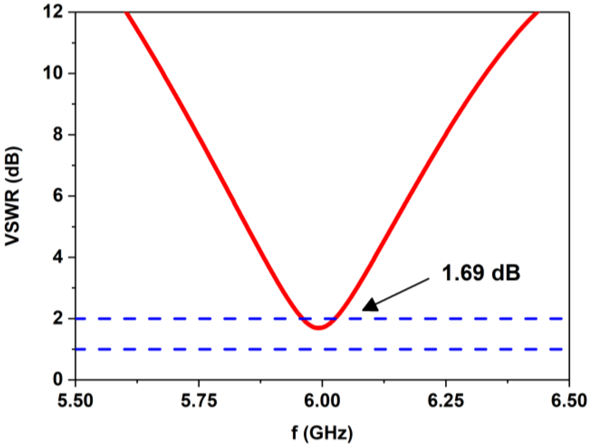
Figure 5 provides a detailed representation of the voltage standing wave ratio (VSWR) as it varies with frequency. The VSWR value can range from 1 to infinity, acting as a crucial parameter in evaluating the efficiency of antennas and their signal transmission capabilities. When antennas are used, standing waves occur if there is a misalignment between the antenna’s impedance and the impedance of the feeding transmission line. This mismatch leads to a portion of the transmitted power being reflected back, which is problematic for effective communication.
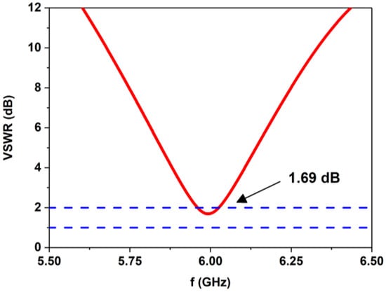
Figure 5.
Voltage standing wave ratio (VSWR).
VSWR gauges the ratio of the voltage that is reflected back to the voltage that is transmitted down the line. For most communication systems, a VSWR value of 2 or lower is deemed acceptable (blue line in Figure 5), indicating that the reflected power is not excessively high compared to the transmitted power. Ideally, a VSWR closer to 1 is preferable, suggesting a near-perfect impedance match, meaning that the majority of power is transmitted effectively without reflection.
In the context of Figure 5, it is observed that the minimum VSWR value achieved is 1.69 at a frequency of 5.99 GHz. This value indicates a satisfactory level of impedance matching, which suggests that the antenna can efficiently transmit signals at this frequency while minimizing losses due to reflection. Therefore, the performance of the antenna at this frequency is commendable, making it suitable for practical applications in communication systems.
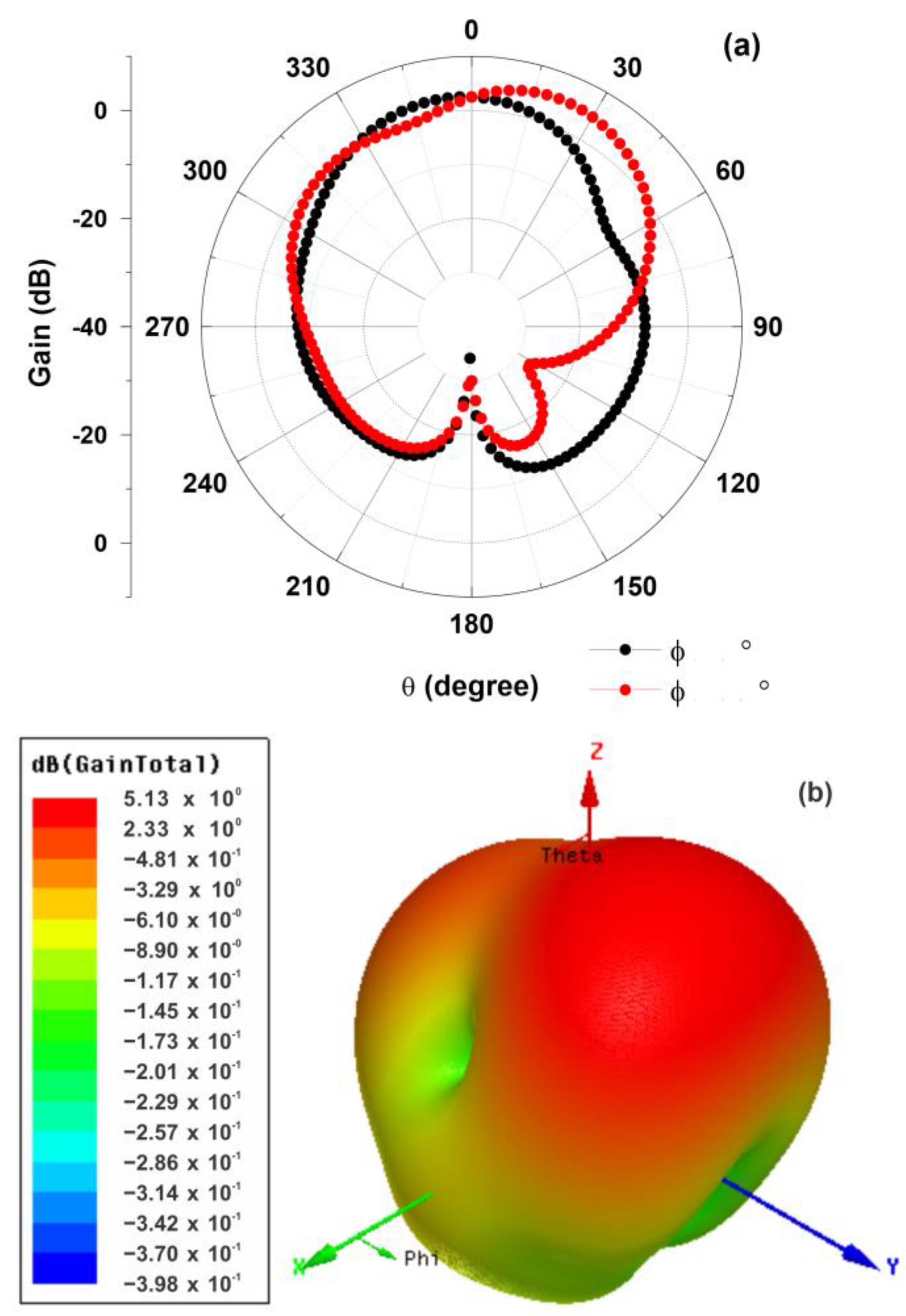
Figure 6a provides a detailed illustration of the gain pattern of the microstrip antenna at two specific azimuthal angles: Phi = 0° and Phi = 90°. This representation indicates how the antenna’s gain responds at these angles when operating at a frequency of 5.99 GHz. In Figure 6b, the 3D gain pattern is depicted, offering a comprehensive view of how the gain intensity changes in three-dimensional space during the antenna’s operation. This 3D representation is crucial for understanding the antenna’s performance, as it highlights not only the maximum gain but also how the gain varies across different angles and positions in the operational environment. Together, both figures provide valuable insights into the directional characteristics and efficiency of the microstrip antenna in practical applications.
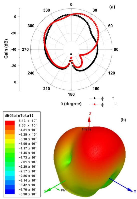
Figure 6.
(a) Gain at ϕ = 0° and ϕ = 90°, and (b) 3D gain total.
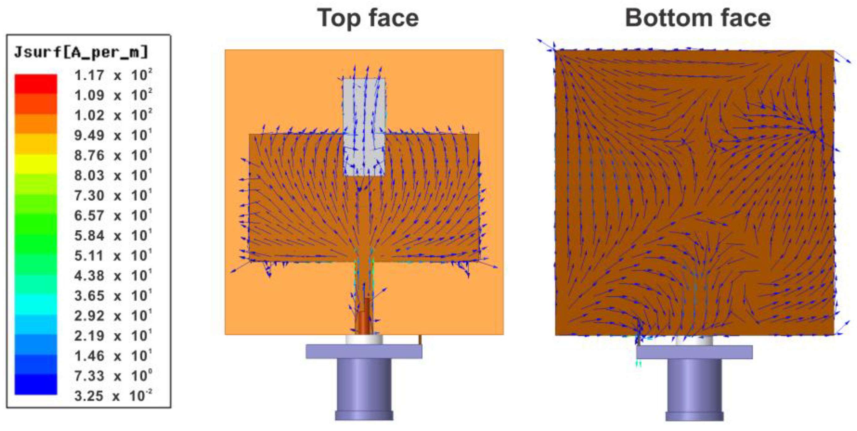
Figure 7 displays the current flow on both the top and bottom sides of the antenna, providing detailed insights into how the electrical currents behave in various components. The top side of the antenna highlights the movement of current, particularly in the probe, the patch, and the sensing element of the microstrip antenna. This visual representation clarifies how the current flux originates from the probe and transitions through to the sensing element, illustrating the connectivity and interaction between these key components in antenna functionality.
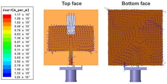
Figure 7.
Current flow in the antenna.
Additionally, Table 2 details the parameters obtained from the numerical simulation, offering a comprehensive overview of critical metrics for data transmission. Among these parameters, we observe an operating frequency of 5.99 GHz, which is optimal for many communication applications; a bandwidth of 340 MHz, indicating the range of frequencies over which the antenna can operate effectively; and a gain of 3.26 dB, representing the increase in signal strength provided by the antenna compared to a standard reference. These parameters are essential for understanding how well the antenna performs in terms of efficiency and reliability in real-world applications.

Table 2.
Antenna radiation parameters.
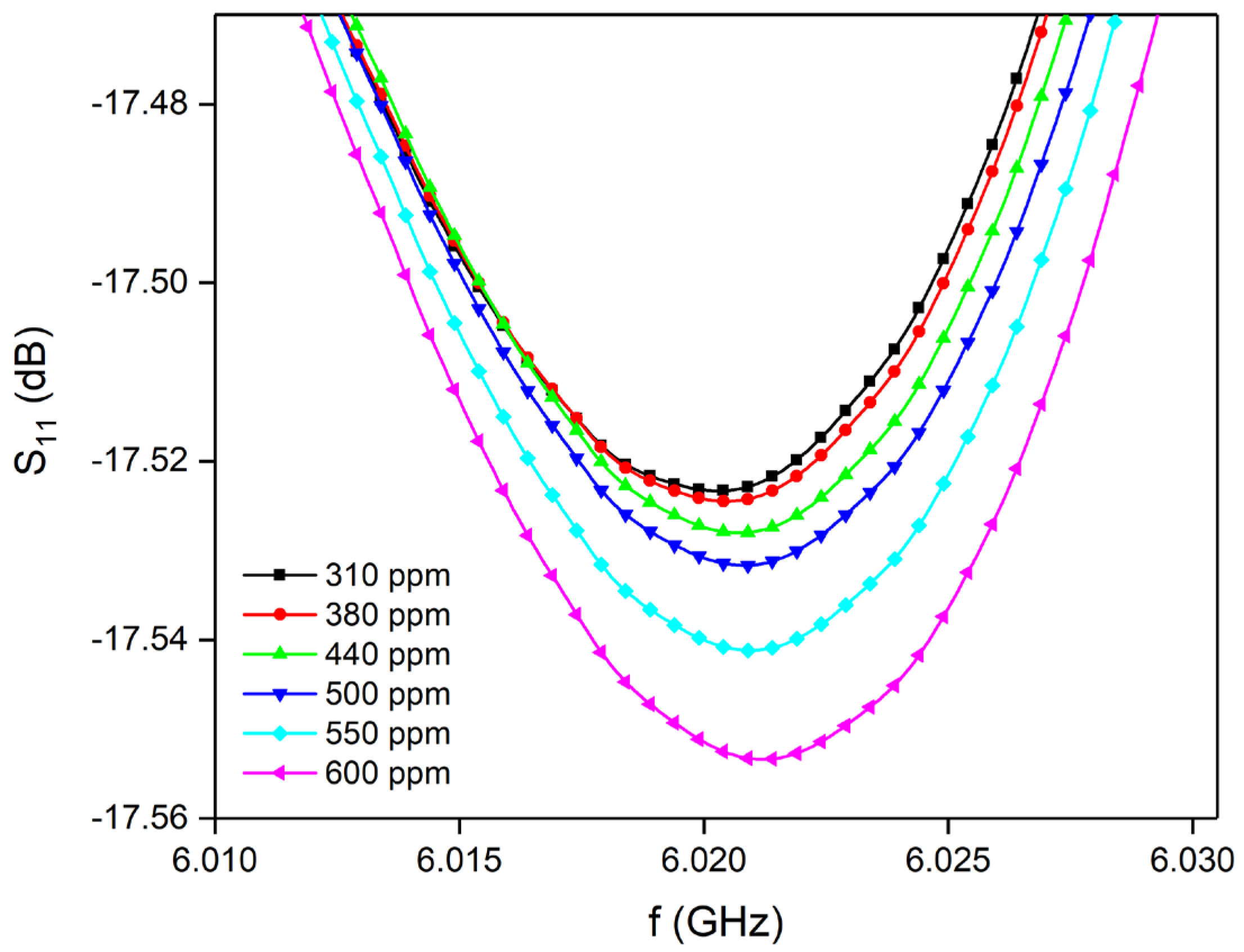
Tests with hydrogen gas were conducted to evaluate the antenna’s performance as a sensor, with results presented in Figure 8 and Figure 9. In Figure 8, we see how the S11 parameter evolves as the concentration of hydrogen gas in the glovebox increases, measured in parts per million (ppm). The observed changes in the antenna’s operating frequency can be attributed to variations in resistance within the silver sensing element, which occurs when hydrogen molecules interact with the film surface. Additionally, it is noteworthy that the sensing signals remain below −10 dB, indicating that the device continues to function properly as an antenna, capable of transmitting data to another device. This low signal level suggests effective interaction between the hydrogen gas and the antenna, essential for its sensing capabilities.
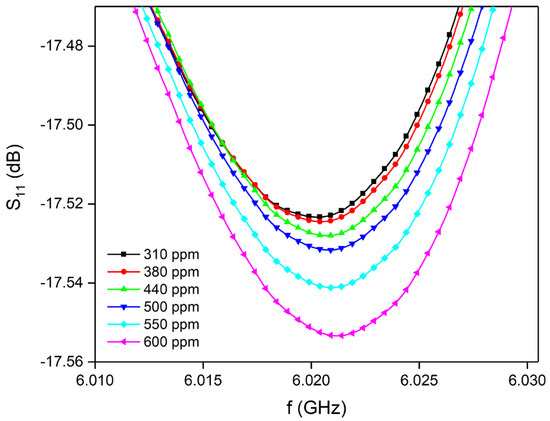
Figure 8.
Evolution of parameter S11 during sensing.
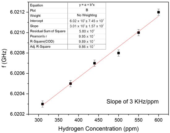
Figure 9.
Hydrogen-sensing rate.
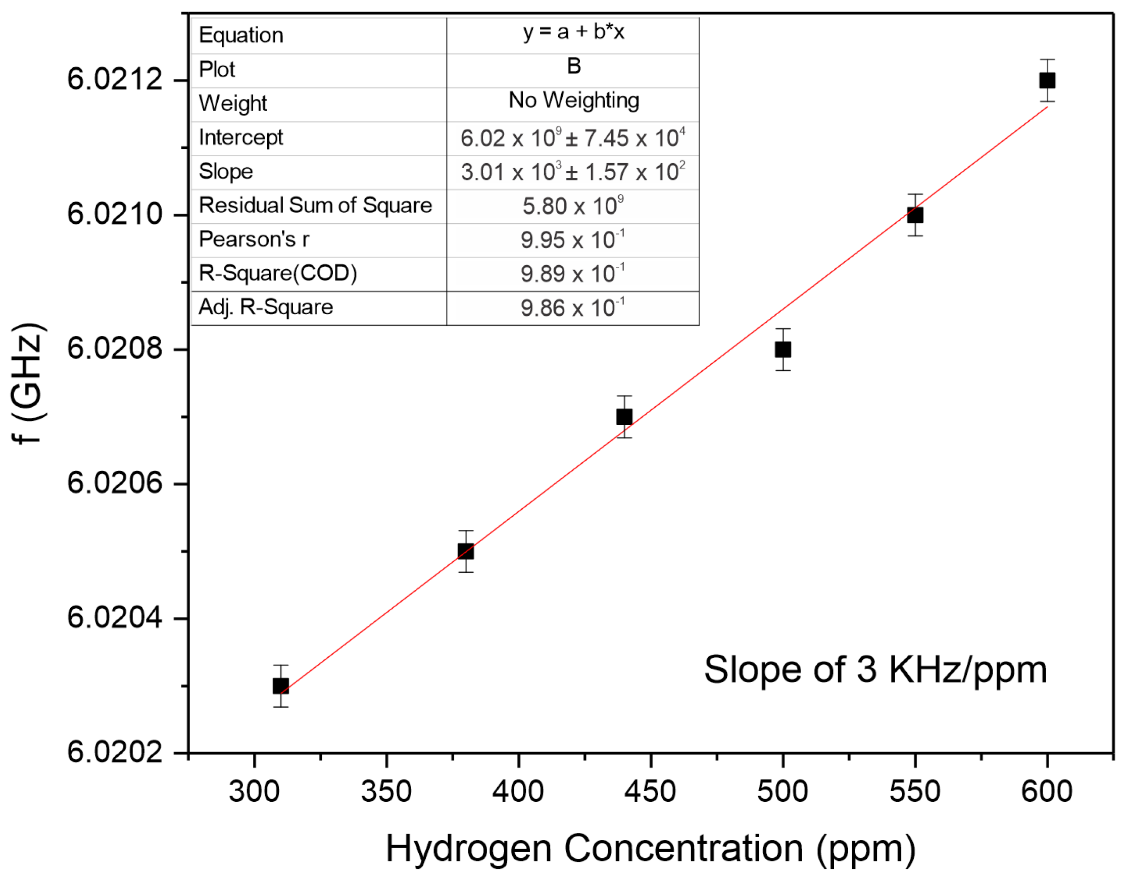
Figure 9 provides a detailed visualization of the linear correlation between the frequency measured at the minimum point of parameter S11 and the corresponding hydrogen concentrations expressed in parts per million (ppm). The graph clearly indicates a significant linear increase in frequency as the hydrogen concentration rises. This trend suggests that the antenna could effectively operate as a hydrogen sensor merely by tracking the shifts in its operating frequency mode in response to varying hydrogen levels. The proposed sensor demonstrated a sensitivity of approximately 3 kHz/ppm in response to increasing hydrogen concentrations, with a residual standard deviation (σ) of 31.1 kHz. This results in a practical resolution or limit of detection (LOD) of about 31 ppm, which is consistent with detection limits reported for other microwave-based hydrogen sensors employing materials such as palladium or graphene oxide [21,36].
Additionally, Table 3 compares the performance of various microstrip-based sensors utilized for hydrogen detection as documented in existing literature. It also includes specific parameters of the sensor antenna developed in this project, allowing for a comprehensive evaluation of its efficacy and performance relative to previously established sensors in the field.

Table 3.
Response of microstrip antenna-based sensors for H2 sensing reported in the literature and this project.
4. Discussion
The numerical study of the patch antenna incorporating a silver sensory element demonstrated high fidelity between experimental measurements and simulations. The reflection parameter S11, as shown in Figure 3a, exhibited strong agreement, validating the accuracy of the simulation model. Similarly, the real and imaginary parts of the impedance (Figure 3b) confirmed the model’s reliability in capturing the antenna’s electrical characteristics. Impedance analysis via Smith chart (Figure 4) revealed that the antenna operates predominantly with lower resistance and positive reactance, indicating inductive behavior. This insight is crucial for optimizing impedance matching and overall efficiency in wireless communication applications. The voltage standing wave ratio (VSWR) measurements (Figure 5) showed a minimum value of 1.69 at 5.99 GHz, indicating effective impedance matching and efficient signal transmission at this frequency. Gain patterns (Figure 6) illustrated directional characteristics, with detailed 3D gain distribution highlighting the antenna’s performance in space. Current flow analysis (Figure 7) provided an understanding of electrical behavior across the antenna’s components, emphasizing the role of the probe, patch, and sensing element in current distribution. The antenna’s operational parameters (Table 2) indicated an optimal frequency of 5.99 GHz, a bandwidth of 340 MHz, and a gain of 3.26 dB, demonstrating suitability for communication systems. When tested as a hydrogen sensor, the antenna maintained proper functioning, with S11 signals remaining below −10 dB, and showed a linear correlation between hydrogen concentration and frequency shift (Figure 8 and Figure 9). This suggests the antenna’s dual functionality as both a communication device and a hydrogen sensor. The fact that the reflection coefficient S11 remains below −10 dB across all sensing conditions indicates that the antenna preserves acceptable impedance matching and radiation characteristics, even as the resonant frequency shifts in response to hydrogen exposure. This dual behavior enables the integration of sensing and wireless transmission functionalities into a single compact component, reducing system complexity and cost. Recent studies, such as that by Alam and Cheffena [41], have explored similar concepts of integrated antenna/sensor systems capable of simultaneously capturing environmental data and transmitting it wirelessly.
In addition to its good functional characteristics as an antenna, the device presents good characteristics as a sensor since the estimated LOD was approximately 31 ppm. Compared to other studies presented in Table 3, the LOD value is within the range required for early detection of leaks in safety-critical systems. In addition, the simplicity of manufacturing, passive operation, and linear response under controlled humidity and temperature conditions make this sensor a competitive and scalable alternative.
While the sensor’s response is attributed to the dielectric modulation induced by hydrogen adsorption onto the silver surface, it is important to recognize that this mechanism may also introduce certain limitations. Specifically, surface contamination by oxygen, water molecules, hydrocarbons, or other ambient species could alter the adsorption dynamics or passivate active sites, thereby affecting sensor sensitivity and reproducibility. Moreover, since the detection principle relies on adsorption in non-specific physisorption and chemisorption processes, the device may exhibit cross-sensitivity to other gases with similar electronic or molecular interactions. To minimize such effects, all experiments were conducted in a glovebox under low humidity and controlled atmospheric conditions. Nonetheless, future investigations will focus on evaluating the influence of surface contaminants, testing the sensor’s analyte discrimination capabilities, and exploring surface functionalization or nanostructuring strategies to improve selectivity and long-term performance. Further research should also address the long-term stability and sensitivity of the antenna as a hydrogen sensor, including evaluations under varying environmental conditions. Optimization of the sensing element’s material properties and geometric configuration could contribute to enhanced detection limits and faster response times. In addition, integrating this dual-function antenna into practical wireless sensor networks and assessing its performance in real-world scenarios will be valuable for advancing both sensor technology and RF communication systems.
5. Conclusions
This study demonstrated the feasibility of using a microstrip patch antenna with a silver sensing element as an effective platform for hydrogen gas detection. The antenna operates at 5.99 GHz, with a measured bandwidth of 340 MHz and an efficiency of 52.55%. Numerical simulations confirmed the antenna’s electromagnetic performance, while experimental results revealed a clear and linear shift in the S11 resonant frequency in response to hydrogen concentrations ranging from 310 to 600 ppm. The sensor exhibited a sensitivity of 3 kHz/ppm and a limit of detection (LOD) of approximately 31 ppm, which is adequate for early leak detection in industrial safety scenarios.
Although long-term cycling tests, selectivity validation against interfering gases, and measurements of response/recovery time were not included in this initial study, the sensor demonstrated stable behavior under controlled humidity and temperature conditions. These results confirm the potential of the proposed antenna to act as a dual-function device, combining gas sensing with RF communication capabilities. Compared to commercial sensors, the present approach offers a low-cost, passive, and scalable solution with promising applications in distributed hydrogen monitoring systems.
This proof-of-concept establishes a foundation for future development of a fully integrated wireless sensor. Ongoing and future research will focus on improving material stability, exploring functional surface modifications to enhance selectivity, implementing real-time monitoring under variable environmental conditions, and integrating the antenna into wireless sensor networks for practical deployment in industrial environments.
6. Patent
The authors declare that the results and technology presented in this article are related to a patent filed with the Brazilian National Institute of Industrial Property (INPI) under application number BR 10 2024 025177 6, entitled “NEW HYDROGEN (H2) SENSOR USING MICROSTRIP ANTENNA WITH SILVER SENSING ELEMENT FOR APPLICATION IN INDUSTRIAL SAFETY SYSTEMS”.
Author Contributions
Conceptualization, A.J.M.S. and A.S.B.S.; methodology, A.J.M.S., S.R.B., J.P.C.d.N. and F.F.d.C.; software, A.J.M.S. and M.A.S.d.S.; validation, F.E.A.N., S.R.B., A.J.M.S. and A.S.B.S.; formal analysis, A.J.M.S., J.A.d.C., S.R.B. and J.C.S.; investigation, S.R.B., A.J.M.S., R.F.A. and F.E.A.N.; resources, J.A.d.C., E.P.d.D., F.E.A.N. and P.M.d.O.S.; data curation, P.M.d.O.S., J.A.d.C., M.A.S.d.S. and J.C.S.; writing—original draft preparation, A.J.M.S., F.F.d.C., S.R.B., E.P.d.D. and P.M.d.O.S.; writing—review and editing, J.P.C.d.N., R.F.A., S.R.B., A.J.M.S. and A.S.B.S.; visualization, M.A.S.d.S., R.F.A., J.C.S., A.J.M.S. and A.S.B.S.; supervision, A.S.B.S.; project administration, A.S.B.S.; funding acquisition, A.S.B.S. All authors have read and agreed to the published version of the manuscript.
Funding
This work was partly sponsored by the Brazilian Research Agencies CNPq—Conselho Nacional de Desenvolvimento Científico e Tecnológico (grants: CNPq/MCTI/SEMPI Nº 26/2022: 409483/2022-2, CNPq/MCTI/FNDCT Nº 18/2022: 405847/2022-0, 27/2022: 407261/2022-2, CT-PETRO Nº 16/2022: 405595/2022-0, CNPq/FNDCT/MCTI 17/2022: 405246/2022-6), CAPES—Coordenação de Aperfeiçoamento de Pessoal de Ensino Superior (grant: Project PNPD), and FINEP—Financiadora de Estudos e Projetos (grants: INFRAPESQ-11 and INFRAPESQ-12). A.J.M.S. acknowledges Conselho Nacional de Desenvolvimento Científico e Tecnológico (CNPq) for the Post-Doctoral grant (PDS/102425/2024-8).
Institutional Review Board Statement
Not applicable.
Informed Consent Statement
Not applicable.
Data Availability Statement
The original contributions presented in this study are included in the article. Further inquiries can be directed to the corresponding author.
Conflicts of Interest
The authors declare that they have no conflicts of interest.
References
- Fisher, J.C.; Nelson, H.H.; Allen, J.K.; Kazempoor, P.; Mistree, F. Analyzing Hydrogen Hub Locations: Resources, Energy, and Social Impact. Int. J. Hydrogen Energy 2024, 70, 641–653. [Google Scholar] [CrossRef]
- Tashie-Lewis, B.C.; Nnabuife, S.G. Hydrogen Production, Distribution, Storage and Power Conversion in a Hydrogen Economy—A Technology Review. Chem. Eng. J. Adv. 2021, 8, 100172. [Google Scholar] [CrossRef]
- Capurso, T.; Stefanizzi, M.; Torresi, M.; Camporeale, S.M. Perspective of the Role of Hydrogen in the 21st Century Energy Transition. Energy Convers. Manag. 2022, 251, 114898. [Google Scholar] [CrossRef]
- Mori, M.; Žvar Baškovič, U.; Stropnik, R.; Lotrič, A.; Katrašnik, T.; Šipec, R.; Lipar, J.; Lesar, Ž.; Drobnič, B. Green Energy Hubs for the Military That Can Also Support the Civilian Mobility Sector with Green Hydrogen. Int. J. Hydrogen Energy 2023, 48, 39138–39153. [Google Scholar] [CrossRef]
- Pezeshki, S.I.; Subedi, A.; Gogiyev, T.; Falegnami, A.; Ustolin, F.; Paltrinieri, N. Functional Resonance Analysis Method for Emerging Risks in Hydrogen Handling: An Analysis of an Experimental Test. J. Saf. Sustain. 2024, 1, 264–275. [Google Scholar] [CrossRef]
- Subedi, A.; Thapa, B. Compendium of Fundamentals of Hydrogen Technology; Kathmandu University: Dhulikhel, Nepal, 2023; ISBN 9789937146043. [Google Scholar]
- Al-Thehabey, O.Y. Investigating the Trend of Hydrogen’s Flame Velocity Profile in Relation to Pressure and Temperature above and below the Adiabatic Point. Int. J. Hydrogen Energy 2021, 46, 38089–38105. [Google Scholar] [CrossRef]
- Miller, J.H.; Page, S.E. Complex Adaptive Systems: An Introduction to Computational Models of Social Life; Princeton University Press: Princeton, NJ, USA, 2009; ISBN 9781400835522. [Google Scholar]
- do Carmo, F.F.; Sales, A.J.M.; Nascimento, J.P.C.d.; da Costa Júnior, A.E.; da Silva Clemente, C.; Mazzetto, S.E.; Maia, S.M.; Frutuoso, R.L.; da Silveira Cavalcante, T.; Cavalcante, C.; et al. Graphene Oxide Microstrip Antenna-Based Sensor for Oxygen Gas Sensing in Medical Applications. Phys. Scr. 2024, 99, 075925. [Google Scholar] [CrossRef]
- Chang, Y.-S.; Chen, F.-K.; Tsai, D.-C.; Kuo, B.-H.; Shieu, F.-S. N-Doped Reduced Graphene Oxide for Room-Temperature NO Gas Sensors. Sci. Rep. 2021, 11, 20719. [Google Scholar] [CrossRef]
- Pandey, S. Highly Sensitive and Selective Chemiresistor Gas/Vapor Sensors Based on Polyaniline Nanocomposite: A Comprehensive Review. J. Sci. Adv. Mater. Devices 2016, 1, 431–453. [Google Scholar] [CrossRef]
- Liu, X.; Cheng, S.; Liu, H.; Hu, S.; Zhang, D.; Ning, H. A Survey on Gas Sensing Technology. Sensors 2012, 12, 9635–9665. [Google Scholar] [CrossRef]
- Bailly, G.; Harrabi, A.; Rossignol, J.; Stuerga, D.; Pribetich, P. Microwave Gas Sensing with a Microstrip InterDigital Capacitor: Detection of NH3 with TiO2 Nanoparticles. Sens. Actuators B Chem. 2016, 236, 554–564. [Google Scholar] [CrossRef]
- de Fonseca, B.; Rossignol, J.; Stuerga, D.; Pribetich, P. Microwave Signature for Gas Sensing: 2005 to Present. Urban Clim. 2015, 14, 502–515. [Google Scholar] [CrossRef]
- Zarifi, M.H.; Sohrabi, A.; Shaibani, P.M.; Daneshmand, M.; Thundat, T. Detection of Volatile Organic Compounds Using Microwave Sensors. IEEE Sens. J. 2015, 15, 248–254. [Google Scholar] [CrossRef]
- Pardue, C.; Naishadham, K.; Song, X.; Swaminathan, M. Integration of Carbon Nanotube Films with SRRs for Air Quality Sensing Applications. In Proceedings of the WAMICON 2014, Tampa, FL, USA, 6 June 2014; pp. 1–3. [Google Scholar]
- Chen, W.T.; Stewart, K.M.E.; Mansour, R.R.; Penlidis, A. Novel Undercoupled Radio-Frequency (RF) Resonant Sensor for Gaseous Ethanol and Interferents Detection. Sens. Actuators A Phys. 2015, 230, 63–73. [Google Scholar] [CrossRef]
- Banerjee, S.; Dutta, P.; Basu, S.; Mishra, S.K.; Appasani, B.; Nanda, S.; Abdulkarim, Y.I.; Muhammadsharif, F.F.; Dong, J.; Jha, A.V.; et al. A New Design of a Terahertz Metamaterial Absorber for Gas Sensing Applications. Symmetry 2022, 15, 24. [Google Scholar] [CrossRef]
- Nickpay, M.-R.; Danaie, M.; Shahzadi, A. Highly Sensitive THz Refractive Index Sensor Based on Folded Split-Ring Metamaterial Graphene Resonators. Plasmonics 2022, 17, 237–248. [Google Scholar] [CrossRef]
- Lee, Y.-J.; Kim, B.-H.; Lee, H.-J.; Hong, Y.; Yook, J.-G.; Choi, H.H.; Lee, S.H.; Lee, J.J. A Reflection Type Gas Sensor Using Conducting Polymer as a Variable Impedance at Microwave Frquencies. In Proceedings of the IEEE SENSORS 2014, Valencia, Spain, 2–5 November 2014; pp. 1819–1822. [Google Scholar]
- do Nascimento, J.P.C.; do Carmo, F.F.; Sales, A.J.M.; Maia, S.M.; Frutuoso, R.L.; da Silveira Cavalcante, T.; Cavalcante, C.; Vieira, J.D.S.; de Carvalho, C.R.R.; Sombra, A.S.B. A Novel Wireless Oxygen Gas Sensor Based on Silver Film Loaded on a Patch Antenna. Mater. Chem. Phys. 2023, 299, 127513. [Google Scholar] [CrossRef]
- Zhao, X.; Xuan, X.; Jiang, D.; Li, H.; Li, C.; Li, M. Wireless Antenna Sensor with CuO@Cu-Vertical Graphene and Cysteine-PDMS Composite for Ethanol Gas Detection. Anal. Chim. Acta 2024, 1319, 342969. [Google Scholar] [CrossRef]
- Kazemi, K.K.; Zarifi, T.; Mohseni, M.; Narang, R.; Golovin, K.; Zarifi, M.H. Smart Superhydrophobic Textiles Utilizing a Long-Range Antenna Sensor for Hazardous Aqueous Droplet Detection plus Prevention. ACS Appl. Mater. Interfaces 2021, 13, 34877–34888. [Google Scholar] [CrossRef]
- Hossain, K.; Cowen, T.; Cheffena, M. Molecularly Imprinted Polymer Based Antenna Sensor for Methanol Vapor Sensing. IEEE Microw. Wirel. Technol. Lett. 2023, 33, 1385–1388. [Google Scholar] [CrossRef]
- Adams, J.D.; Emam, S.; Sun, N.; Ma, Y.; Wang, Q.; Shashidhar, R.; Sun, N.-X. A Molecularly Imprinted Polymer-Graphene Sensor Antenna Hybrid for Ultra Sensitive Chemical Detection. IEEE Sens. J. 2019, 19, 6571–6577. [Google Scholar] [CrossRef]
- Wu, W.; Shi, G.; Yin, B.; Li, K.; Tang, X. Passive Ammonia Detection Sensor Based on Zinc Stannate Loaded Dual-Frequency Chipless RFID Technique. 2024. Available online: https://ssrn.com/abstract=4965595 (accessed on 10 June 2025).
- Wu, B.; Zhang, X.; Huang, B.; Zhao, Y.; Cheng, C.; Chen, H. High-Performance Wireless Ammonia Gas Sensors Based on Reduced Graphene Oxide and Nano-Silver Ink Hybrid Material Loaded on a Patch Antenna. Sensors 2017, 17, 2070. [Google Scholar] [CrossRef] [PubMed]
- Costa do Nascimento, J.P.; do Carmo, F.F.; Mangueira Sales, A.J.; Sales, J.C.; da Costa Júnior, A.E.; da Silva Clemente, C.; Mazzetto, S.E.; Bezerra Sombra, A.S. Evaluation of the Performance of a Graphene Oxide Microstrip Antenna-Based Sensor for CO2 Gas Sensing. Mater. Lett. 2025, 385, 138204. [Google Scholar] [CrossRef]
- Verma, R.; Said, K.; Salim, J.; Kimathi, E.; Rizkalla, M.; Shrestha, S.; Agarwal, M.; Varahramyan, K. Carbon Nanotube-Based Microstrip Antenna Gas Sensor. In Proceedings of the 2013 IEEE 56th International Midwest Symposium on Circuits and Systems (MWSCAS), Columbus, OH, USA, 4–7 August 2013; pp. 724–727. [Google Scholar]
- Kozak, R.; Khorsand, K.; Zarifi, T.; Golovin, K.; Zarifi, M.H. Patch Antenna Sensor for Wireless Ice and Frost Detection. Sci. Rep. 2021, 11, 13707. [Google Scholar] [CrossRef]
- Sprunger, P.T.; Plummer, E.W. Interaction of hydrogen with the Ag(110) surface. Phys. Rev. B 1993, 48, 14436. [Google Scholar] [CrossRef]
- Lee, G.; Sprunger, P.T.; Okada, M.; Poker, D.B.; Zehner, D.M.; Plummer, E.W. Chemisorption of hydrogen on the Ag(111) surface. J. Vac. Sci. Technol. A 1994, 12, 2119–2123. [Google Scholar] [CrossRef]
- Pez, G.P.; Steyert, W.A. Method for Adsorbing and Storing Hydrogen at Cryogenic Temperatures. 1985. Available online: https://www.freepatentsonline.com/4580404.html (accessed on 2 June 2025).
- Züttel, A. Hydrogen storage methods. Naturwissenschaften 2004, 91, 157–172. [Google Scholar] [CrossRef]
- Uwiringiyimana, J.P.; Khayam, U.; Suwarno; Montanari, G.C. Design and Implementation of Ultra-Wide Band Antenna for Partial Discharge Detection in High Voltage Power Equipment. IEEE Access 2022, 10, 10983–10994. [Google Scholar] [CrossRef]
- Silva dos Santos, K.; Cavalcanti, G.O.; Azevedo, A.; do Nascimento Silva, C.P.; De Melo, M.T.; Llamas-Garro, I.; Fontana, E. Hybrid Microstrip Device for Hydrogen Detection at Microwave Frequencies. IEEE Sens. J. 2023, 23, 6810–6821. [Google Scholar] [CrossRef]
- Dos Santos, K.S.; Cavalcanti, G.O.; Brito-Brito, Z.; Llamas-Garro, I.; Fontana, E. Reconfigurable U-Shaped Microwave Resonator for the Construction of a Hydrogen Sensor. In Proceedings of the 2023 SBMO/IEEE MTT-S International Microwave and Optoelectronics Conference (IMOC), Castelldefels, Spain, 5–9 November 2023; pp. 133–135. [Google Scholar]
- Kanto, N.; Lianjie, Z.; Kato, F.; Nagakubo, A.; Ogi, H. 1Pa3-5 Development of Battery-Free Long-Range Wireless Hydrogen-Gas Sensor Using High-Frequency QCM Resonator. Proc. Symp. Ultrason. Electron. 2022, 43, 37. [Google Scholar] [CrossRef]
- Kato, F.; Sato, Y.; Ato, H.; Kuwabara, H.; Kobayashi, Y.; Nakamura, K.; Masumoto, N.; Noguchi, H.; Ogi, H. Study on Micropillar Arrangement Optimization of Wireless-Electrodeless Quartz Crystal Microbalance Sensor and Application to a Gas Sensor. Jpn. J. Appl. Phys. 2021, 60, SDDC01. [Google Scholar] [CrossRef]
- Kato, F.; Ato, H.; Ichikawa, S.; Kimura, M.; Hasegawa, T.; Ryunosuke, R.; Masumoto, N.; Suzuki, M.; Ogi, H. Improvement of Hydrogen Detection Sensitivity of Palladium Film by In-Plane Compressive Plastic Deformation and Application to Hydrogen Gas Sensor. Jpn. J. Appl. Phys. 2022, 61, 126501. [Google Scholar] [CrossRef]
- Alam, T.; Cheffena, M. Integrated Microwave Antenna/Sensor for Sensing and Communication Applications. IEEE Trans. Microw. Theory Tech. 2022, 70, 5289–5300. [Google Scholar] [CrossRef]
Disclaimer/Publisher’s Note: The statements, opinions and data contained in all publications are solely those of the individual author(s) and contributor(s) and not of MDPI and/or the editor(s). MDPI and/or the editor(s) disclaim responsibility for any injury to people or property resulting from any ideas, methods, instructions or products referred to in the content. |
© 2025 by the authors. Licensee MDPI, Basel, Switzerland. This article is an open access article distributed under the terms and conditions of the Creative Commons Attribution (CC BY) license (https://creativecommons.org/licenses/by/4.0/).

