
Advanced Direct Vector Control Method for Optimizing the Operation of a Double-Powered Induction Generator-Based Dual-Rotor Wind Turbine System


Abstract
:1. Introduction
- ✓
- A new DVC control scheme is proposed and designed for the DFIG-based DRWP system.
- ✓
- The proposed DVC control scheme with fuzzy PWM technique and neural algorithms is a robust strategy compared to classical DVC control with PI controllers and improves the dynamic performances of the DFIG-based DRWP system.
- ✓
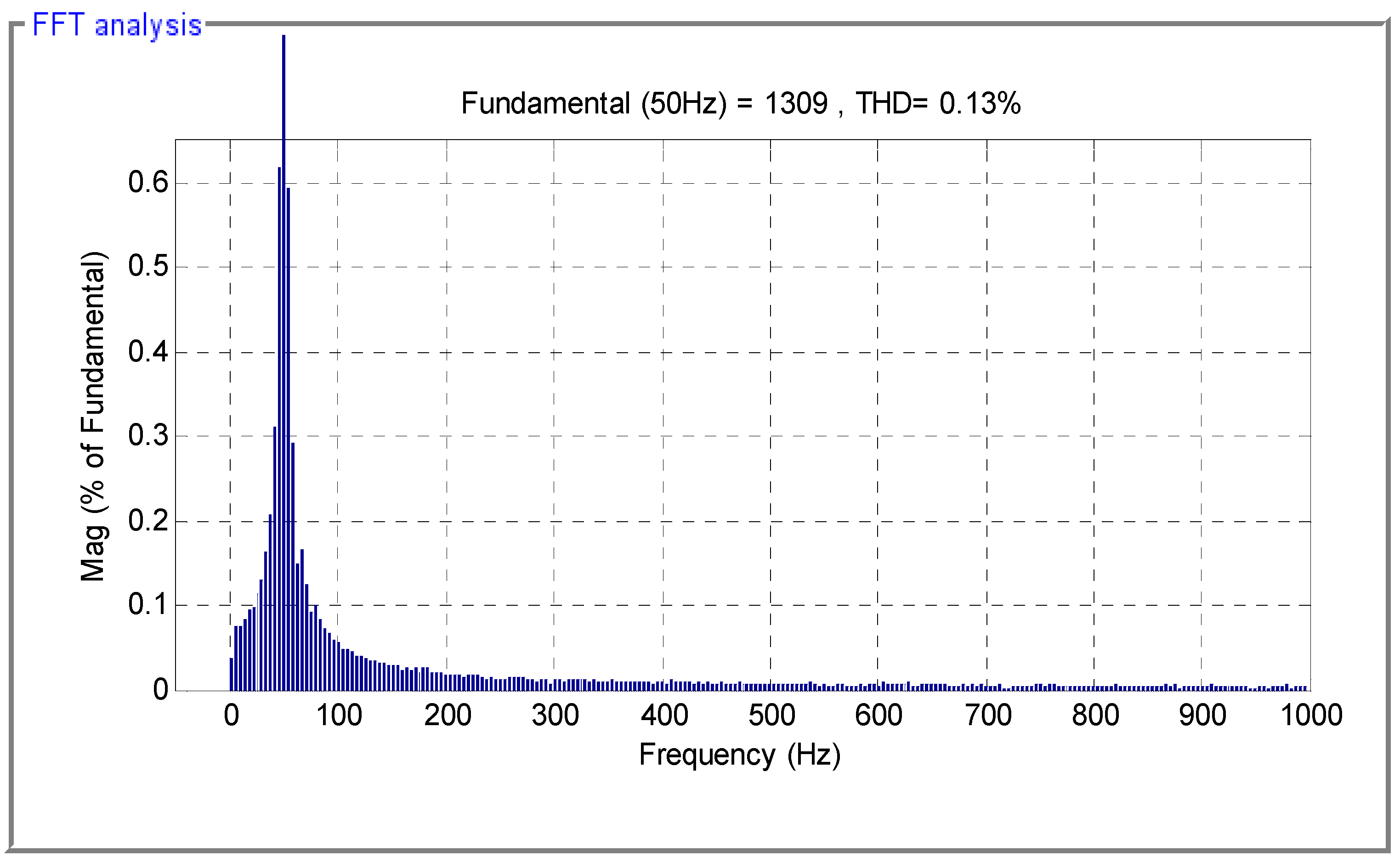
- The proposed method is simple and therefore easier to implement compared to the traditional technique. In addition, the proposed method reduces the reactive and active power ripples and minimizes the total harmonic distortion value of the stator current of DFIG compared to other reference strategies proposed in the literature.
2. Related Work
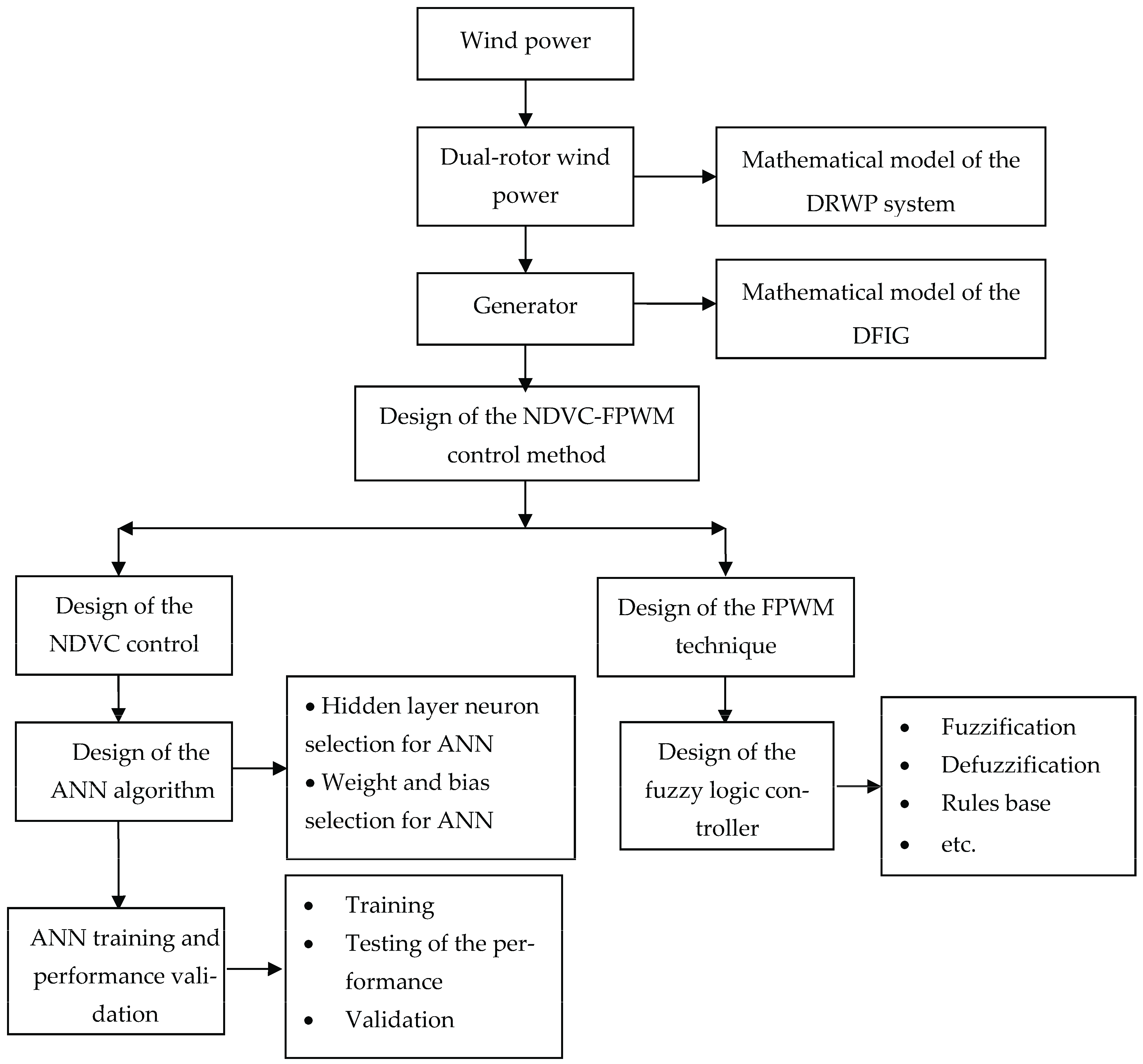
3. Material and Method
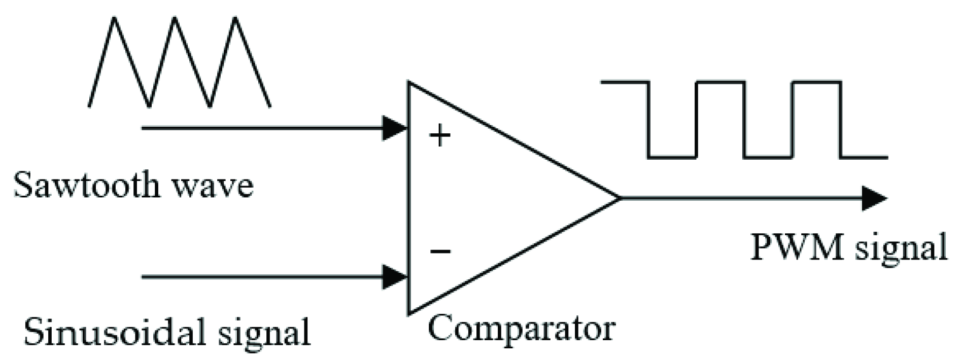
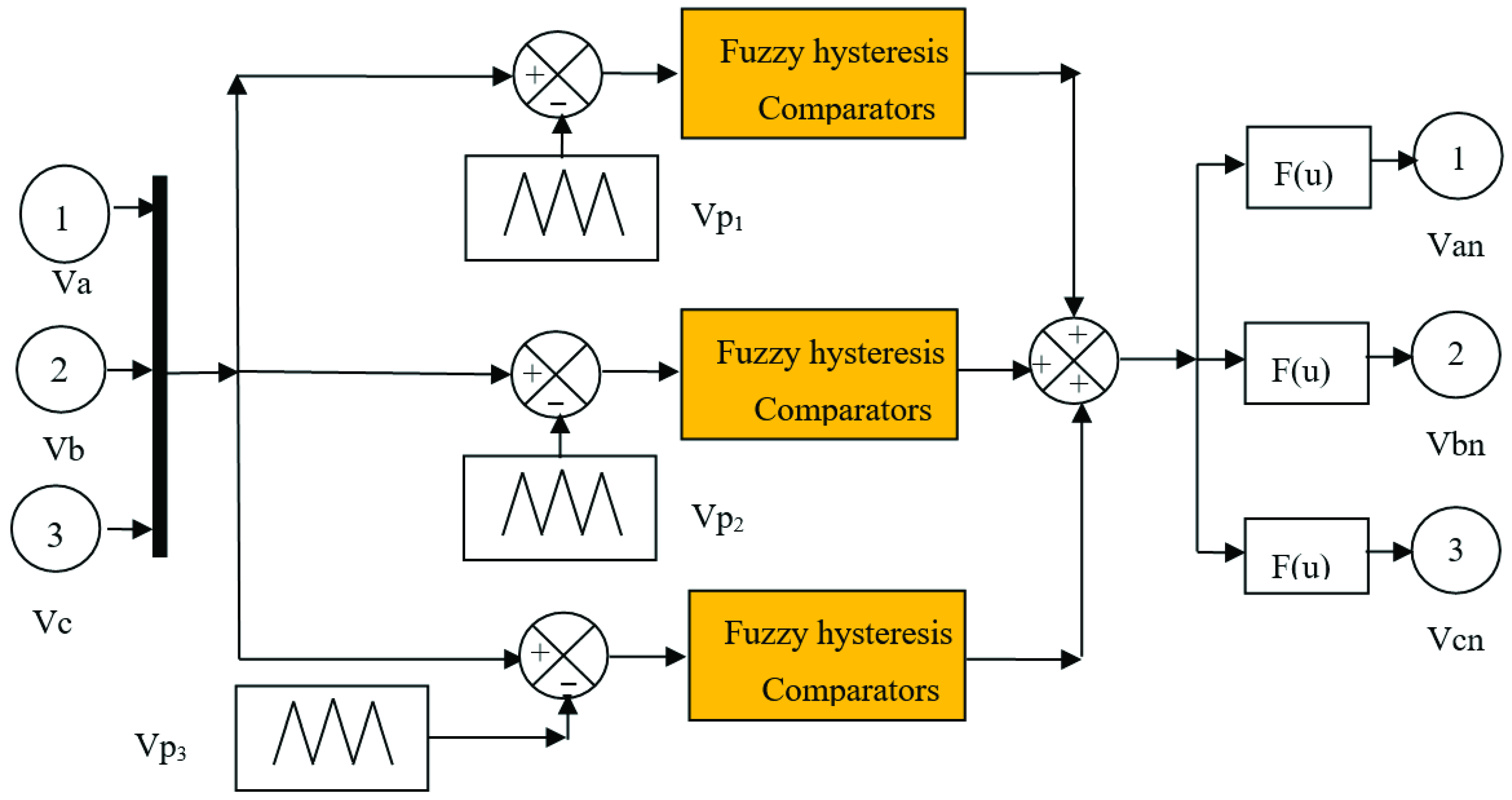
3.1. Fuzzy PWM Technique
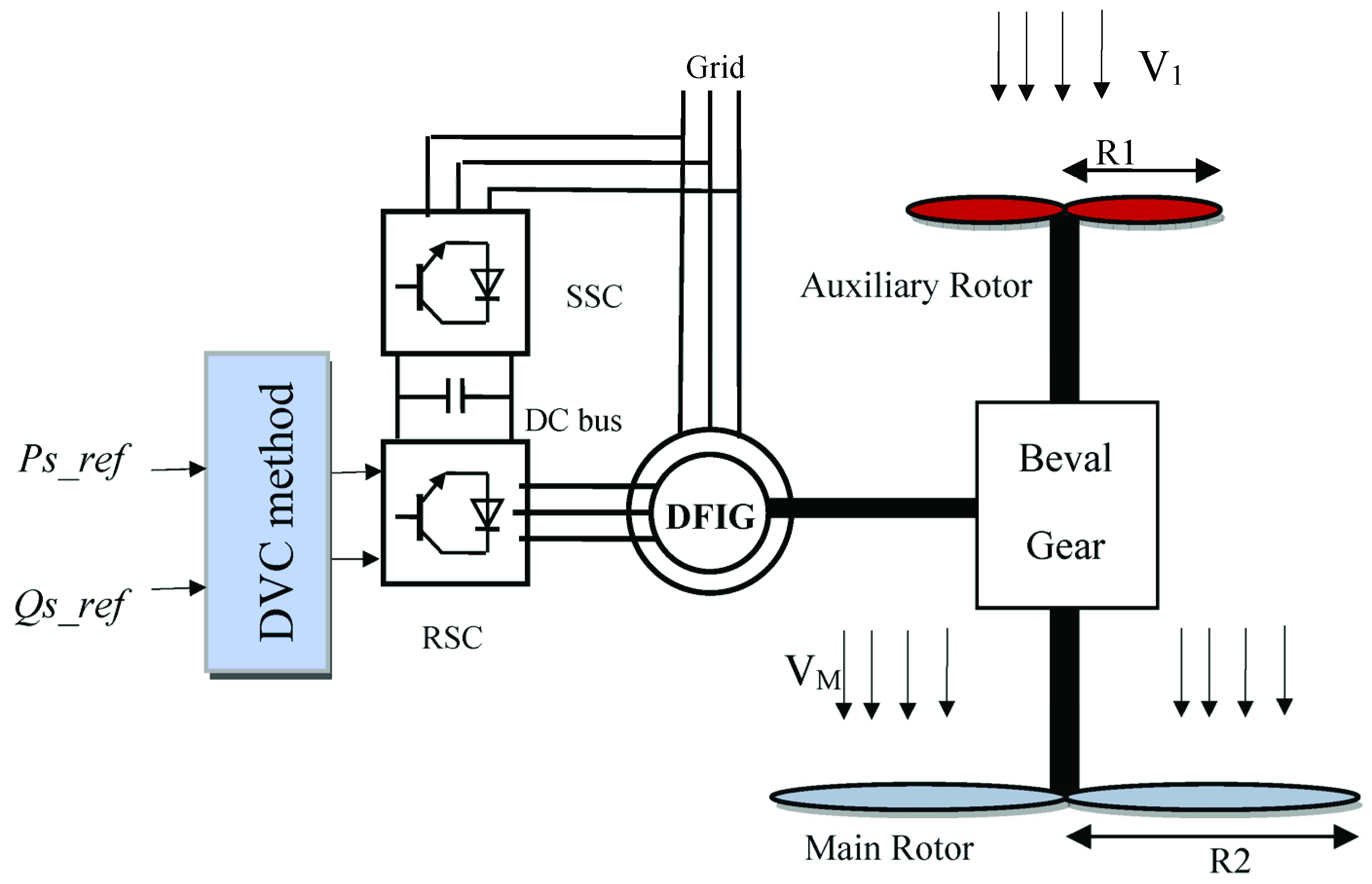
3.2. DRWP Model
- PM: Main turbine power.
- PA: Auxiliary turbine power.
- PT: Total aerodynamic power.
- TM: Main turbine torque.
- TA: Auxiliary turbine torque.
- TT: Total aerodynamic torque.
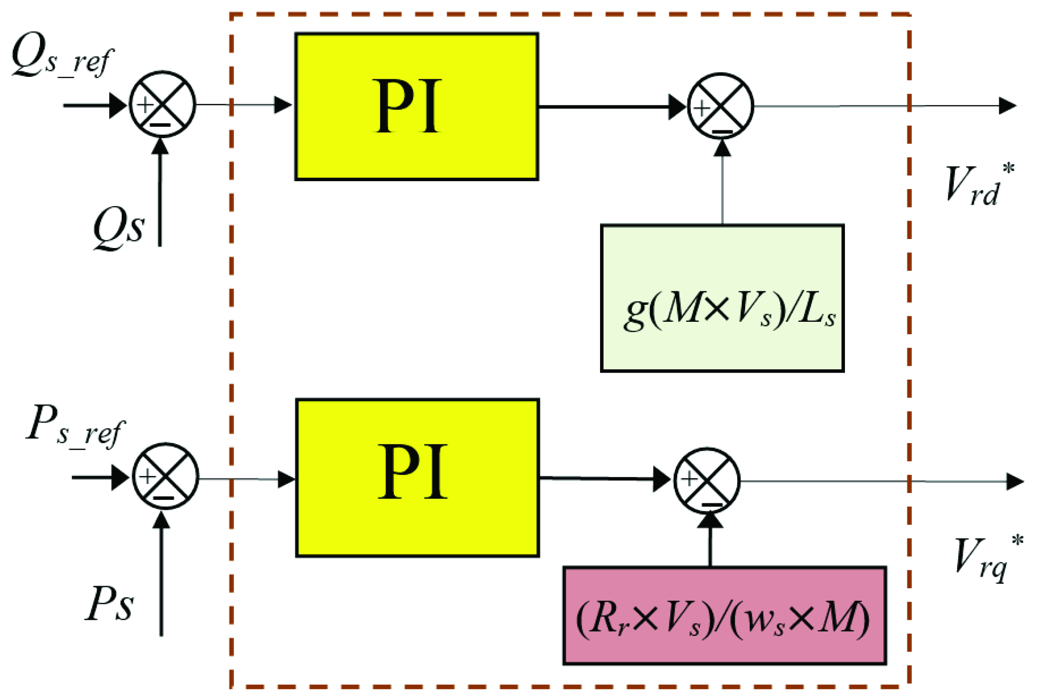
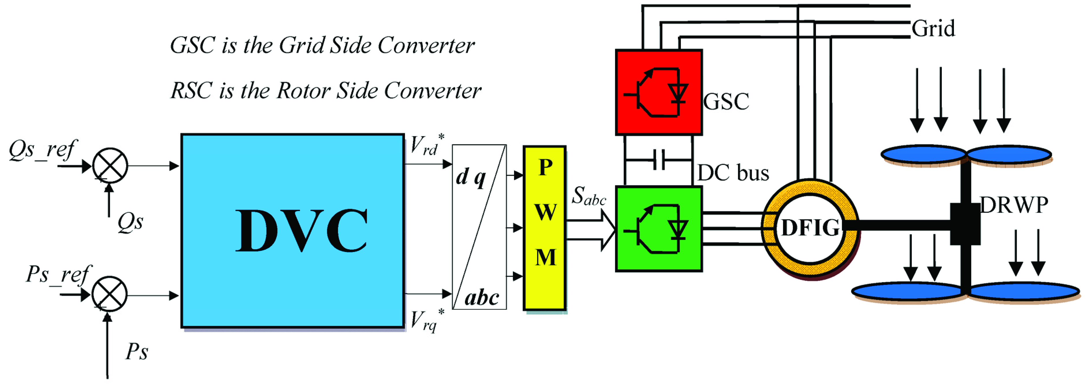
3.3. DVC Method
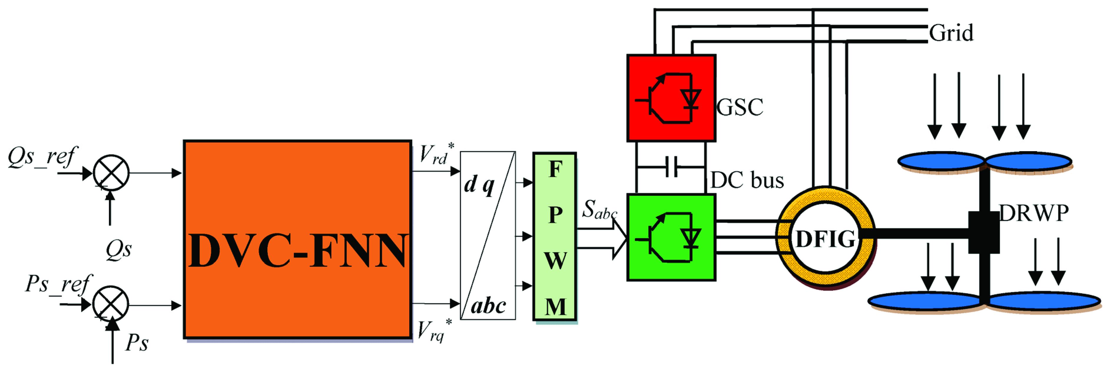
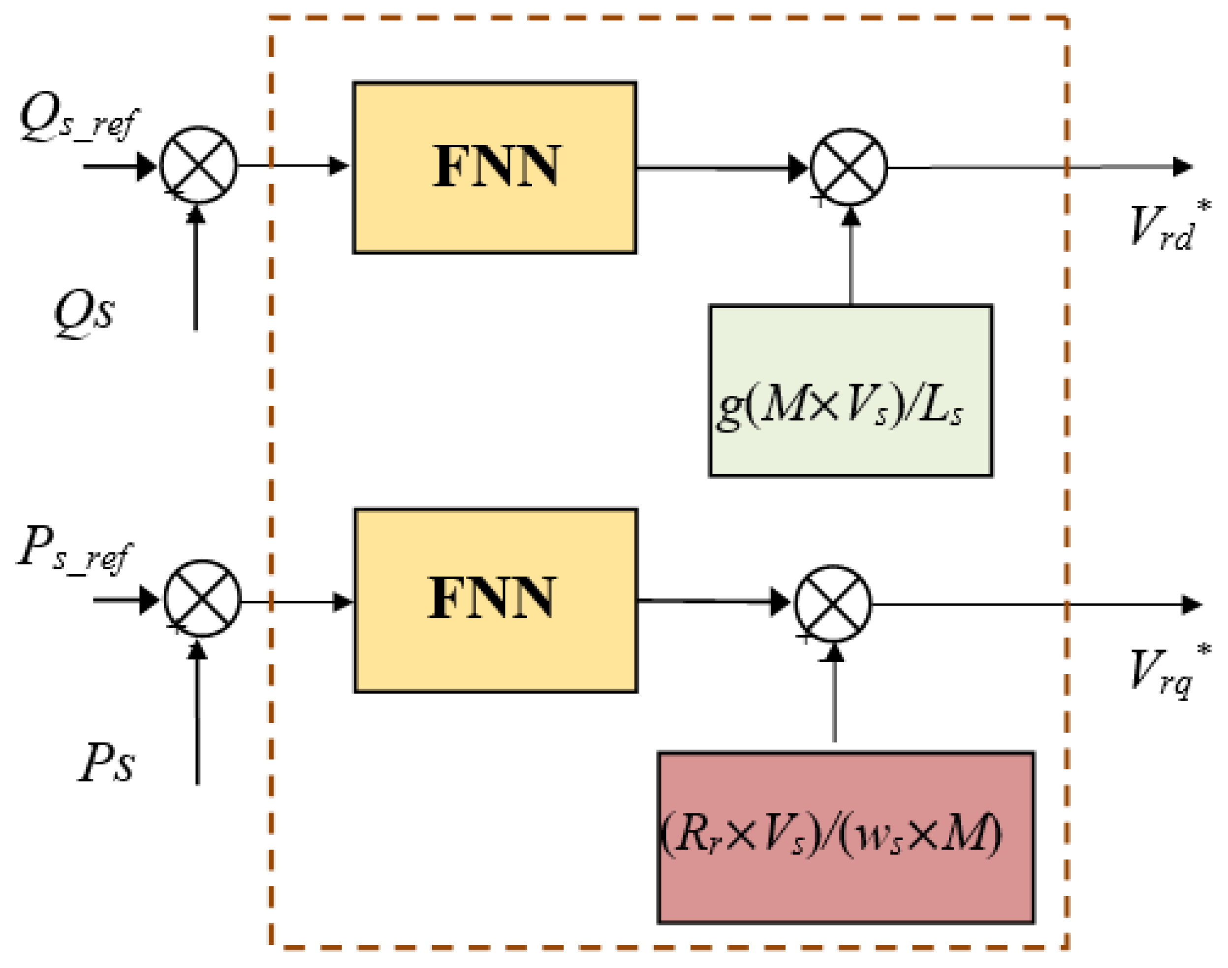
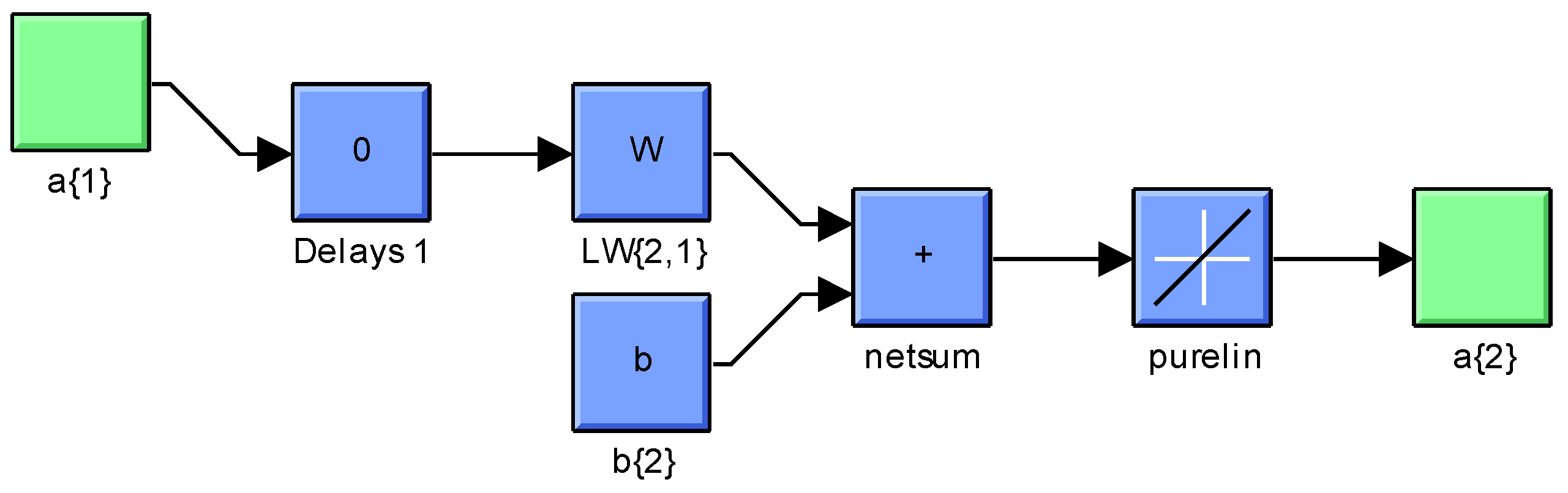
3.4. Neural DVC Method with FPWM Technique
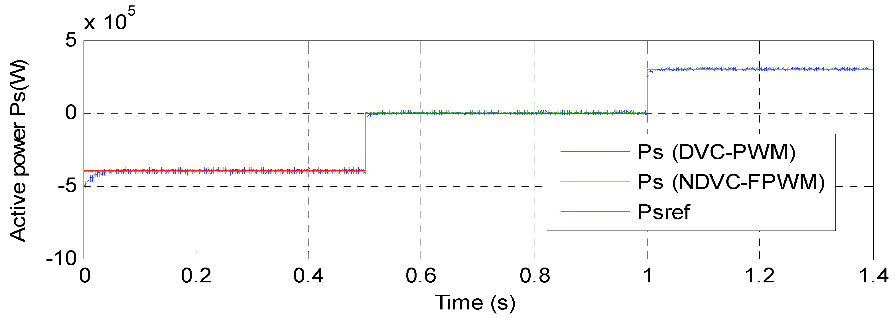
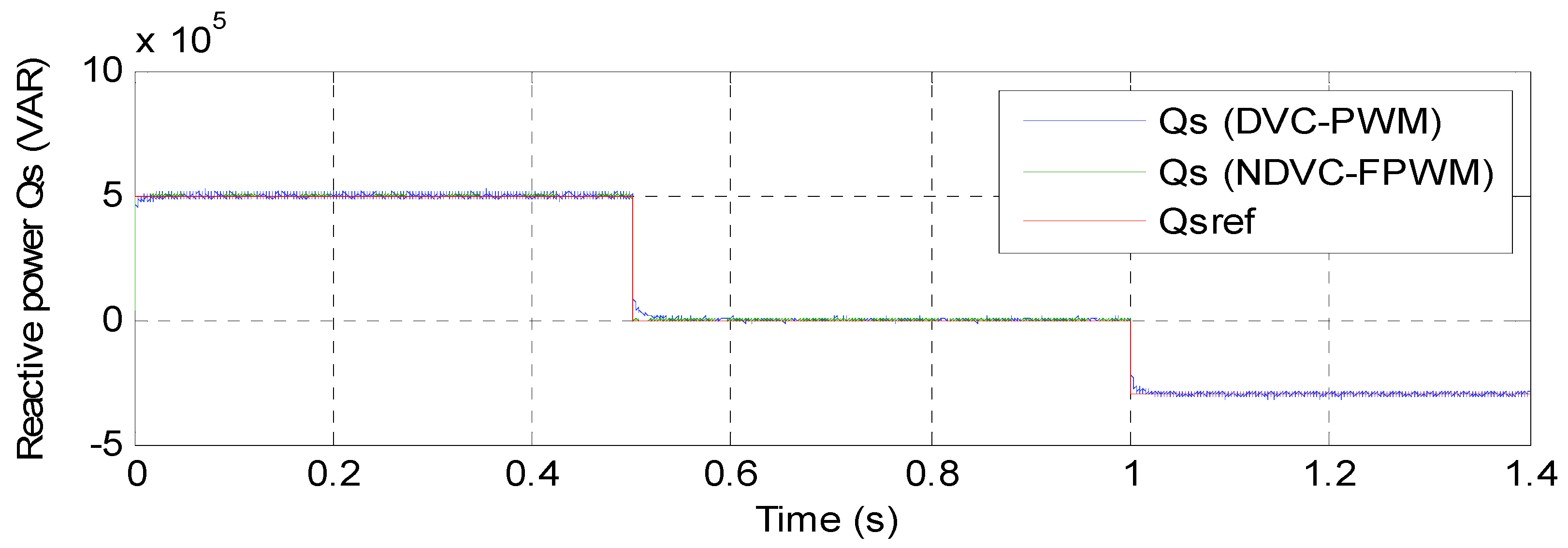
4. Results
5. Conclusions
- A new four-level FPWM technique was presented and confirmed with numerical simulation.
- A new DVC control scheme based on neural network and four-level FPWM technique was presented and confirmed with numerical simulation.
- Minimizes the reactive power, stator current, electromagnetic torque, and active power ripples.
- A robust control scheme was proposed.
- Reduce the harmonic distortion of stator current.
Author Contributions
Funding
Institutional Review Board Statement
Informed Consent Statement
Data Availability Statement
Conflicts of Interest
Abbreviations
| List of Symbols: | |
| ϕr, ϕr* | Actual and reference rotor flux |
| Te, Te* | Actual and reference torques |
| ωn, ωr | Nominal and rotor speeds |
| θr | Rotor flux angle |
| p | Generator pole pairs |
| λ | Tip speed ration |
| Vm | Wind speed |
| Pn | Nominal Power |
| Vs, Is | Vectors of the stator voltage and current |
| Vra,b,c, Ira,b,c | Rotor voltage and current in abc frame |
| Vα,β, Iα,β | Voltage and current in αβ frame |
| Rs, Rr | Stator and rotor resistances |
| ϕαs, ϕβs | Stator flux components in αβ frame |
| Ω | Ohm (unit) |
| Ki, Kp | Integral and proportional gains |
| Lr, Ls, Lm | Rotor, stator, and mutual inductances |
| wb | Weber (unit) |
| Hz | Hertz (unit) |
| MW | Migawatt (Unit) |
| mH | Millihenry (unit) |
| N.m | Newton-meter (Unit) |
| List of Acronyms: | |
| DVC | Direct vector control |
| PI | Proportional integral |
| FLC | fuzzy logic controller |
| FNN | Feedforward neural networks |
| DPC | Direct power control |
| SMC | Sliding mode control |
| IVC | Indirect vector control |
| VAWT | Vertical axis wind turbine |
| HAWT | Horizontal axis wind turbine |
| THD | Total harmonic distortion |
| PWM | Pulse width modulation |
| FOC | Field-oriented control |
| DRWT | Dual-rotor wind turbine |
| FSMC | Fuzzy sliding mode control |
| TSMC | Terminal sliding mode controller |
| SVM | Space vector modulation |
| IP | Integral-proportional |
| DFIG | doubly-fed induction generator |
| FPWM | Fuzzy Pulse width modulation |
| DRWP | Dual-rotor wind power |
| NDVC | Neural direct vector control |
| MRSMC | Multi-resonant-based sliding mode controller |
| ISMC | Integral sliding mode controller. |
Appendix A

| References | Study Nature | Control | Controller | Type of Generator | Complexity | Current Oscillations | Reference Tracking | Dynamic Responses |
|---|---|---|---|---|---|---|---|---|
| Ref. [7] | Simulation | FOC | PI | DFIG | Low | High | ++ | + |
| Ref. [8] | Simulation | FOC | FOPI | DFIG | High | Low | +++ | ++ |
| Ref. [9] | Simulation | Nonlinear control | Fuzzy SOSMC | DFIG | High | Neglected | +++ | +++ |
| Ref. [10] | Simulation | Amplitude control | PI | DFIG | Low | Low | ++ | ++ |
| Ref. [11] | Simulation | DPC | SOSMC | DFIG | High | Neglected | +++ | ++++ |
| Ref. [12] | Simulation | FOC | PI | DFIG | Low | High | ++ | + |
| Ref. [13] | Simulation | DPC | Synergetic STA | DFIG | Medium | Low | +++ | ++++ |
| Ref. [14] | Simulation | Nonlinear control | TSMC | DFIG | High | Neglected | +++ | +++ |
| Ref. [15] | Simulation | Fractional-order command | FOPI | DFIG | Medium | Low | +++ | ++ |
| Ref. [16] | Simulation | Nonlinear control | Backstepping control | DFIG | High | Neglected | +++ | +++ |
| Ref. [17] | Simulation | DPC | FGA | DFIG | Medium | Low | ++ | +++ |
| Ref. [18] | Simulation | DPC | Backstepping control | DFIG | High | Neglected | +++ | ++++ |
| Ref. [19] | Simulation | Nonlinear control | Feedback linearization control | DFIG | High | Neglected | +++ | ++ |
| Ref. [20] | Simulation | DPC | VOC | DFIG | Medium | Low | ++ | +++ |
| Ref. [21] | Simulation | SDC | SDC | DFIG | Medium | Low | ++ | +++ |
| Ref. [22] | Simulation | DPC | MPC | DFIG | Medium | Low | +++ | +++ |
| Ref. [23] | Simulation | DPC | SOSMC | DFIG | High | Low | ++++ | ++++ |
| Ref. [24] | Simulation | DPC | DC voltage regulation | DFIG | Medium | Low | +++ | ++ |
| Ref. [25] | Simulation | FOC | STFOTSMC | DFIG | High | Low | +++ | +++ |
| Ref. [26] | Simulation | DPC | Adaptive High SMC | DFIG | High | Low | +++ | ++++ |
| Ref. [27] | Simulation | DPC | Extended power theory | DFIG | Medium | High | +++ | ++ |
| Ref. [28] | Simulation | FOC | Full-order adaptive observer | DFIG | High | Low | ++ | ++ |
| Ref. [29] | Experimental | Nonlinear control | Feedback linearization | DFIG | High | Low | +++ | +++ |
| Ref. [30] | Simulation | Nonlinear control | Fuzzy SOSMC | DFIM | High | Neglected | ++++ | ++++ |
| Ref. [31] | Simulation | SOSMC | MOO | DFIG | Medium | Low | ++ | +++ |
| Ref. [32] | Simulation | DTC | Hysteresis comparator | DFIG | Medium | High | ++ | ++ |
| Ref. [33] | Simulation | DPC | SMC | DFIG | Medium | Neglected | ++++ | +++ |
| Ref. [34] | Simulation | Nonlinear control | SMC | DFIG | High | Neglected | ++ | +++ |
| Ref. [35] | Experimental | Nonlinear control | Fuzzy fractional order robust command | DFIG | High | Neglected | +++ | ++++ |
| Ref. [36] | Simulation | DPC | MPS | DFIG | Medium | Low | ++ | +++ |
| Ref. [37] | Simulation | DPC | Neural controller | DFIG | Medium | Low | ++++ | +++ |
| Ref. [38] | Simulation | FOC | PI | DFIG | Low | High | ++ | + |
| Ref. [39] | Simulation | DTC | Resonant current control | DFIG | Medium | High | +++ | ++ |
| Ref. [40] | Simulation | DTC | PI | DFIG | Low | Low | +++ | ++ |
| Ref. [41] | Simulation | FOC | PI | DFIG | Low | High | ++ | + |
| Ref. [42] | Simulation | FOC | Neuro-fuzzy | DFIG | Medium | Low | ++ | ++ |
| Ref. [43] | Simulation | DVC | Fuzzy SMC | DFIG | Medium | Neglected | ++++ | +++ |
| Ref. [44] | Simulation | FOC | Neural SOSMC | DFIG | High | Low | ++ | +++ |
| Ref. [45] | Simulation | DVC | PI | DFIG | Low | High | ++ | + |
| Ref. [46] | Experimental | IVC | PI | DFIG | Low | High | ++ | + |
| Ref. [47] | Simulation | DPC | Neuro-fuzzy | DFIG | Medium | Low | +++ | +++ |
| Ref. [48] | Experimental | IVC | Hysteresis rotor current controller | DFIG | Medium | Low | ++ | ++ |
Appendix B. Design of the Fuzzy Logic Controller

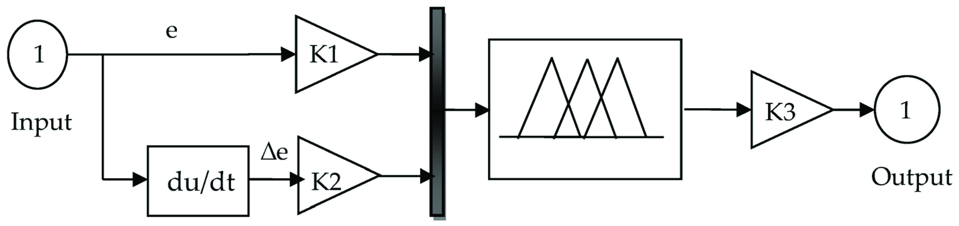
| e | NB | NM | NS | EZ | PS | PM | PB |
|---|---|---|---|---|---|---|---|
| ∆e | |||||||
| PB | EZ | PS | PM | PB | PB | PB | PB |
| EZ | NB | NM | NS | EZ | PS | PM | PB |
| NM | NB | NB | NB | NM | NS | EZ | PS |
| NB | NB | NB | NB | NB | NM | NS | EZ |
| PM | NS | EZ | PS | PM | PB | PB | PB |
| PS | NM | NS | EZ | PS | PM | PB | PB |
| NS | NB | NB | NM | NS | EZ | PS | PM |

| Or method | Max |
| And method | Min |
| FIS type | Mamdani |
| Defuzzification | Centroid |
| Implication | Min |
| Aggregation | Max |


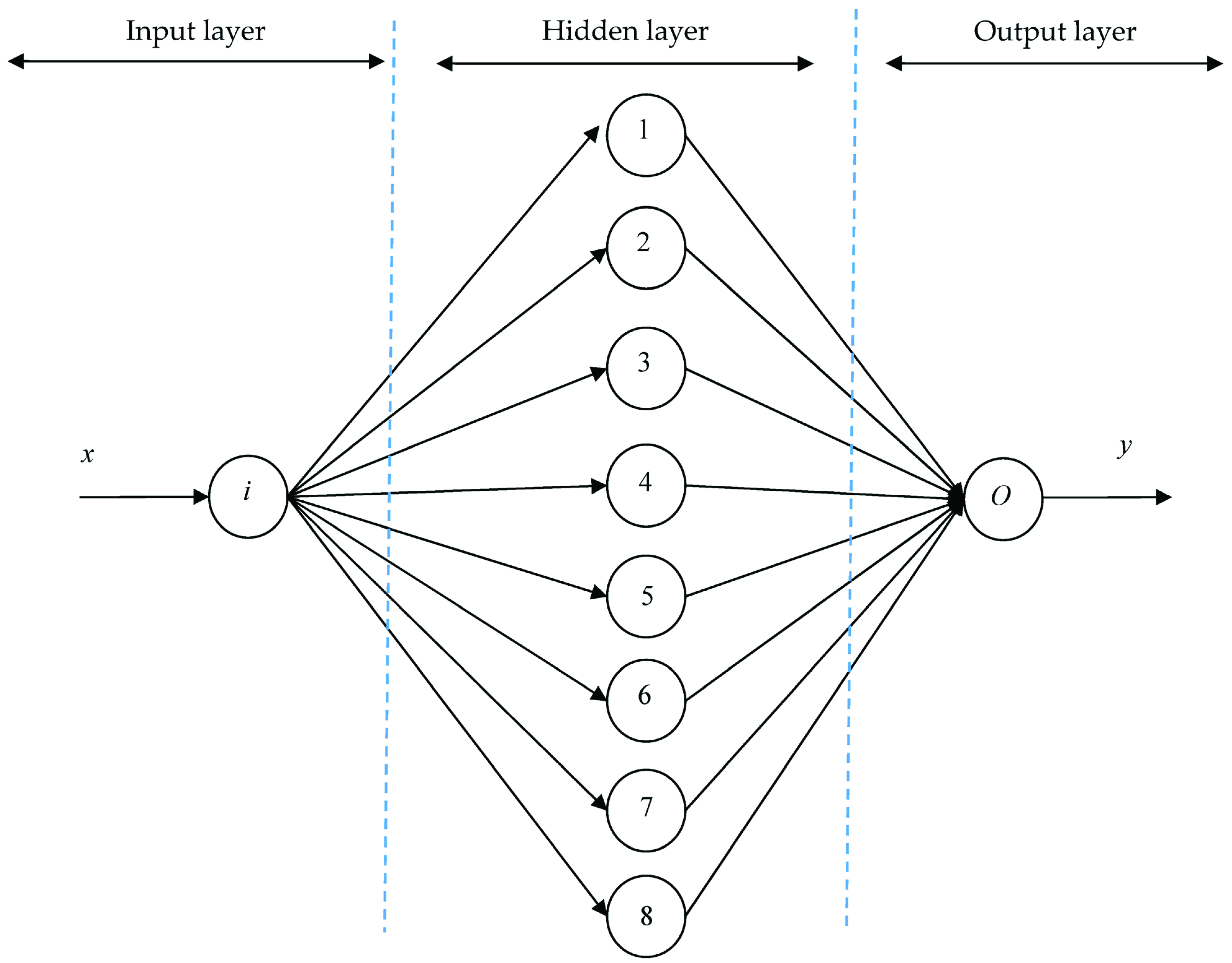
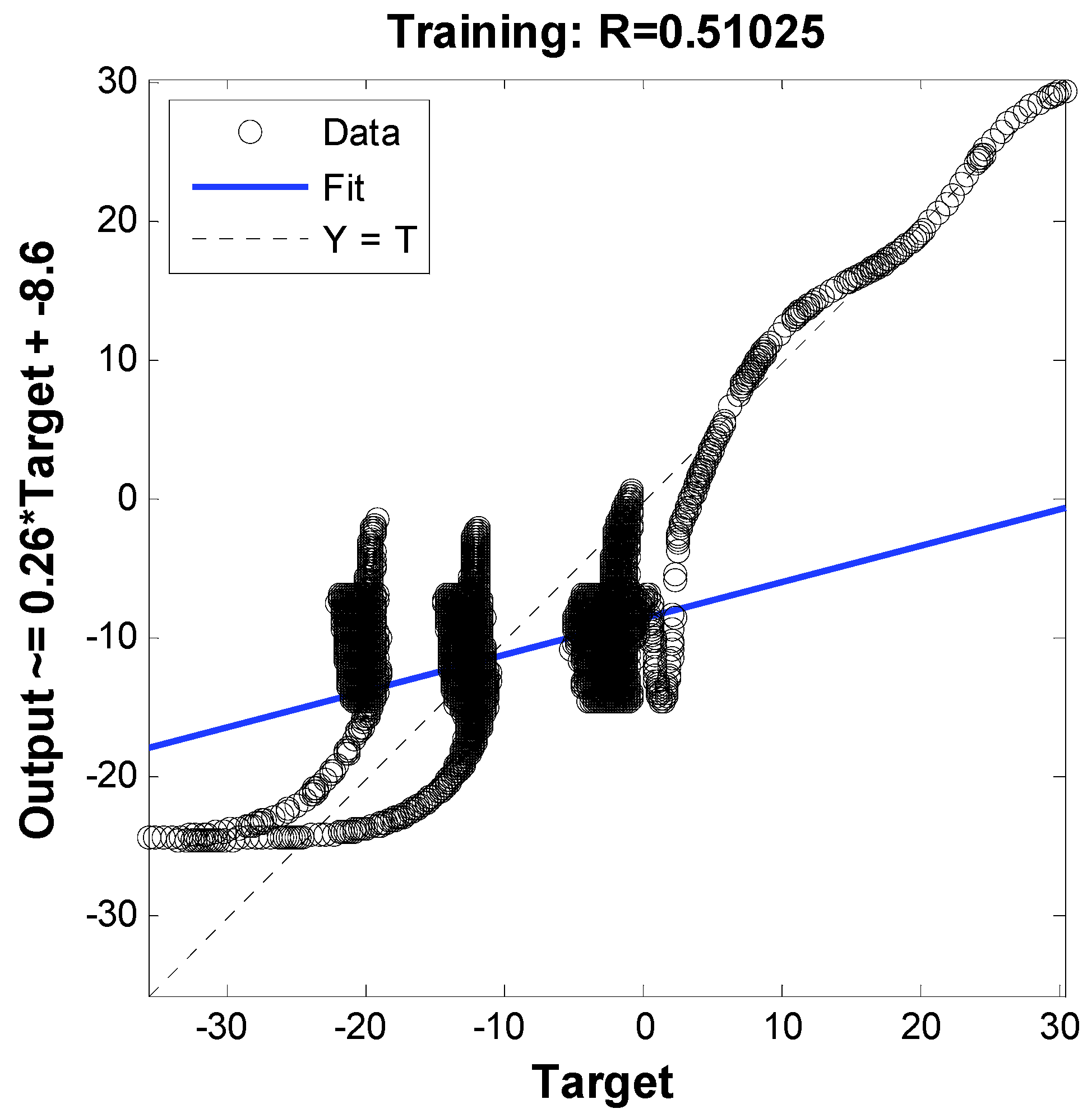
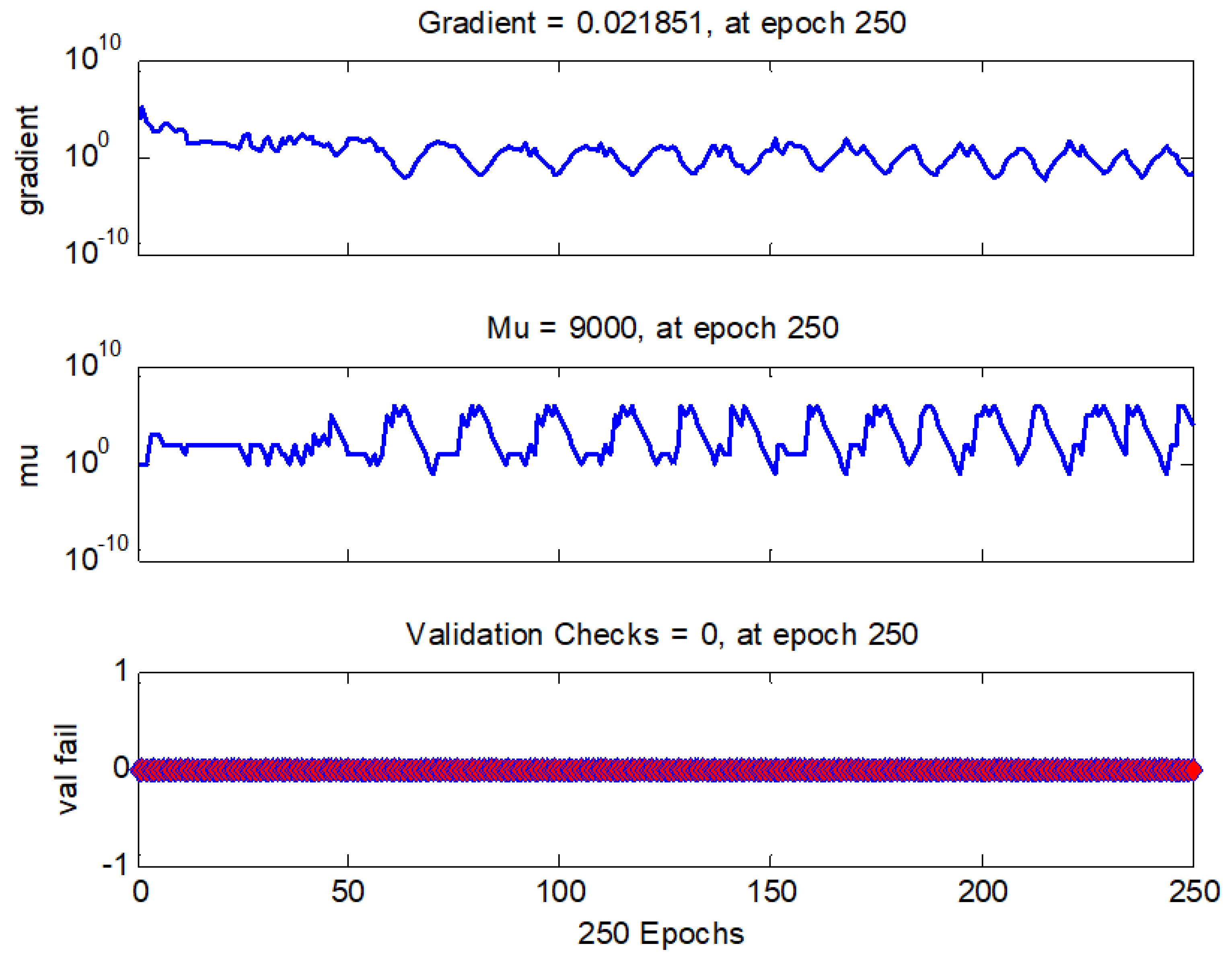
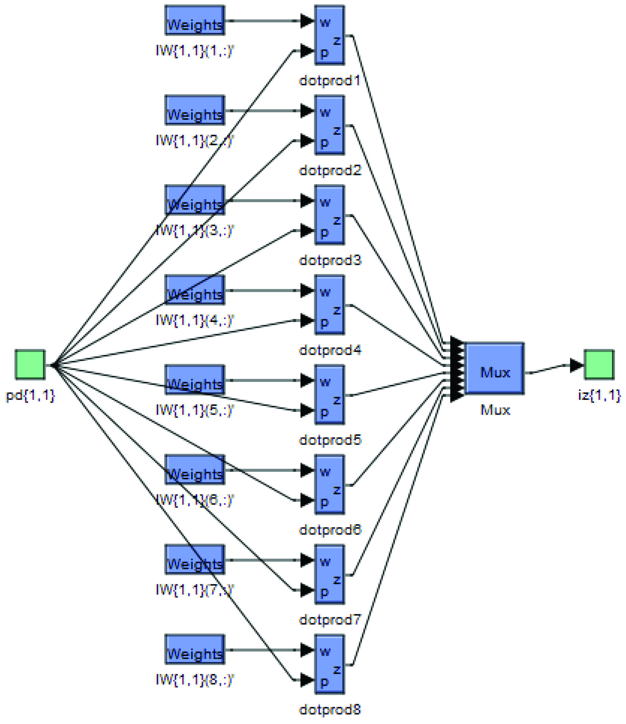
Appendix C. Design of the Feedforward Neural Network

| Parameters | Values |
|---|---|
| Performances | Mean Squared Error (mse) |
| Training | Levenberg-Marquardt algorithm (trainlm) |
| TrainParam.show | 50 |
| TrainParam.Lr | 0.05 |
| Neurons of output layer | 1 |
| TrainParam.goal | 0 |
| TrainParam.mu | 0.8 |
| Neurons of input layer | 1 |
| Coeff. of acceleration of convergence (mc) | 0.9 |
| Derivative | Default (default deriv) |
| Number of hidden layers | 1 |
| Functions of activation | Tensing, Purling, trainlm |
| Number of output layer | 1 |
| TrainParam.eposh | 250 |
| Number of input layer | 1 |
| Neurons of hidden layer | 8 |


References
- Kumar, P.M.; Sivalingam, K.; Lim, T.-C.; Ramakrishna, S.; Wei, H. Strategies for Enhancing the Low Wind Speed Performance of H-Darrieus Wind Turbine—Part 1. Clean Technol. 2019, 1, 185–204. [Google Scholar] [CrossRef] [Green Version]
- Kumar, P.M.; Sivalingam, K.; Lim, T.-C.; Ramakrishna, S.; Wei, H. Review on the Evolution of Darrieus Vertical Axis Wind Turbine: Large Wind Turbines. Clean Technol. 2019, 1, 205–223. [Google Scholar] [CrossRef] [Green Version]
- Manousakis, N.; Psomopoulos, C.; Ioannidis, G.; Kaminaris, S. A Binary Integer Programming Method for Optimal Wind Turbines Allocation. Clean Technol. 2021, 3, 462–473. [Google Scholar] [CrossRef]
- AlGhamdi, S.; Hamdan, I.; Youssef, M.; Noureldeen, O. Development and Application of Fuzzy Proportional-Integral Control Scheme in Pitch Angle Compensation Loop for Wind Turbines. Machines 2021, 9, 135. [Google Scholar] [CrossRef]
- Abdelrahem, M.; Hackl, C.; Kennel, R. Limited-Position Set Model-Reference Adaptive Observer for Control of DFIGs without Mechanical Sensors. Machines 2020, 8, 72. [Google Scholar] [CrossRef]
- Chen, H.; Xie, W.; Chen, X.; Han, J.; Aït-Ahmed, N.; Zhou, Z.; Tang, T.; Benbouzid, M. Fractional-Order PI Control of DFIG-Based Tidal Stream Turbine. J. Mar. Sci. Eng. 2020, 8, 309. [Google Scholar] [CrossRef]
- Alhato, M.; Ibrahim, M.; Rezk, H.; Bouallègue, S. An Enhanced DC-Link Voltage Response for Wind-Driven Doubly Fed Induction Generator Using Adaptive Fuzzy Extended State Observer and Sliding Mode Control. Mathematics 2021, 9, 963. [Google Scholar] [CrossRef]
- Cortajarena, J.A.; Barambones, O.; Alkorta, P.; Cortajarena, J. Grid Frequency and Amplitude Control Using DFIG Wind Turbines in a Smart Grid. Mathematics 2021, 9, 143. [Google Scholar] [CrossRef]
- Alhato, M.M.; Bouallègue, S.; Rezk, H. Modeling and Performance Improvement of Direct Power Control of Doubly-Fed Induction Generator Based Wind Turbine through Second-Order Sliding Mode Control Approach. Mathematics 2020, 8, 2012. [Google Scholar] [CrossRef]
- Giaourakis, D.G.; Safacas, A.N. Effect of Short-Circuit Faults in the Back-to-Back Power Electronic Converter and Rotor Terminals on the Operational Behavior of the Doubly-Fed Induction Generator Wind Energy Conversion System. Machines 2015, 3, 2–26. [Google Scholar] [CrossRef] [Green Version]
- Benbouhenni, H.; Lemdani, S. Combining synergetic control and super twisting algorithm to reduce the active power undulations of doubly fed induction generator for dual-rotor wind turbine system. Electr. Eng. Electromechanics 2021, 8–17. [Google Scholar] [CrossRef]
- Zahedi, A.H.; Arab, M.G.; Taghipour, B.S. Sliding Mode and Terminal Sliding Mode Control of Cascaded Doubly Fed In-duction Generator. IJEEE 2021, 17, 1955. Available online: http://ijeee.iust.ac.ir/article-1-1955-en.html (accessed on 1 September 2021).
- Hosseinabadi, M.; Rastegar, H. DFIG Based Wind Turbines Behavior Improvement during Wind Variations using Fractional Order Control Systems. IJEEE 2014, 10, 314–323. Available online: http://ijeee.iust.ac.ir/article-1-663-en.html (accessed on 1 September 2021).
- Pour Ebrahim, R.; Tohidi, S.; Younesi, A. Sensorless Model Reference Adaptive Control of DFIG by Using High Frequency Signal Injection and Fuzzy Logic Control. IJEEE 2018, 14, 11–21. [Google Scholar] [CrossRef]
- Heydari, E.; Rafiee, M.; Pichan, M. Fuzzy-Genetic Algorithm-Based Direct Power Control Strategy for DFIG. IJEEE 2018, 14, 353–361. Available online: http://ijeee.iust.ac.ir/article-1-1185-en.html (accessed on 1 September 2021).
- Djeriri, Y. Lyapunov-Based Robust Power Controllers for a Doubly Fed Induction Generator. IJEEE 2020, 16, 551–558. Available online: http://ijeee.iust.ac.ir/article-1-1596-en.html (accessed on 1 September 2021).
- Kaloi, G.S.; Baloch, M.H.; Kumar, M.; Soomro, D.M.; Chauhdary, S.T.; Memon, A.A.; Ishak, D. An LVRT Scheme for Grid Connected DFIG Based WECS Using State Feedback Linearization Control Technique. Electronics 2019, 8, 777. [Google Scholar] [CrossRef] [Green Version]
- Mossa, M.A.; Echeikh, H.; Diab, A.A.Z.; Quynh, N.V. Effective Direct Power Control for a Sensor-Less Doubly Fed Induction Generator with a Losses Minimization Criterion. Electronics 2020, 9, 1269. [Google Scholar] [CrossRef]
- Peng, X.; Chen, R.; Zhou, J.; Qin, S.; Bi, R.; Sun, H. Research on Mechanism and Damping Control Strategy of DFIG-Based Wind Farm Grid-Connected System SSR Based on the Complex Torque Method. Electronics 2021, 10, 1640. [Google Scholar] [CrossRef]
- Cui, H.; Li, X.; Wu, G.; Song, Y.; Liu, X.; Luo, D. MPC Based Coordinated Active and Reactive Power Control Strategy of DFIG Wind Farm with Distributed ESSs. Energies 2021, 14, 3906. [Google Scholar] [CrossRef]
- Han, Y.; Ma, R. Adaptive-Gain Second-Order Sliding Mode Direct Power Control for Wind-Turbine-Driven DFIG under Balanced and Unbalanced Grid Voltage. Energies 2019, 12, 3886. [Google Scholar] [CrossRef] [Green Version]
- Medeiros, A.; Ramos, T.; De Oliveira, J.T.; Júnior, M.F.M. Direct Voltage Control of a Doubly Fed Induction Generator by Means of Optimal Strategy. Energies 2020, 13, 770. [Google Scholar] [CrossRef] [Green Version]
- Sami, I.; Ullah, S.; Ali, Z.; Ullah, N.; Ro, J.-S. A Super Twisting Fractional Order Terminal Sliding Mode Control for DFIG-Based Wind Energy Conversion System. Energies 2020, 13, 2158. [Google Scholar] [CrossRef]
- Han, Y.; Li, S.; Du, C. Adaptive Higher-Order Sliding Mode Control of Series-Compensated DFIG-Based Wind Farm for Sub-Synchronous Control Interaction Mitigation. Energies 2020, 13, 5421. [Google Scholar] [CrossRef]
- Cheng, P.; Wu, C.; Ning, F.; He, J. Voltage Modulated DPC Strategy of DFIG Using Extended Power Theory under Unbalanced Grid Voltage Conditions. Energies 2020, 13, 6077. [Google Scholar] [CrossRef]
- Ma, R.; Han, Y.; Pan, W. Variable-Gain Super-Twisting Sliding Mode Damping Control of Series-Compensated DFIG-Based Wind Power System for SSCI Mitigation. Energies 2021, 14, 382. [Google Scholar] [CrossRef]
- Brando, G.; Dannier, A.; Spina, I. Performance Analysis of a Full Order Sensorless Control Adaptive Observer for Doubly-Fed Induction Generator in Grid Connected Operation. Energies 2021, 14, 1254. [Google Scholar] [CrossRef]
- Kroplewski, P.; Morawiec, M.; Jąderko, A.; Odeh, C. Simulation Studies of Control Systems for Doubly Fed Induction Generator Supplied by the Current Source Converter. Energies 2021, 14, 1511. [Google Scholar] [CrossRef]
- Napole, C.; Barambones, O.; Derbeli, M.; Cortajarena, J.; Calvo, I.; Alkorta, P.; Bustamante, P. Double Fed Induction Generator Control Design Based on a Fuzzy Logic Controller for an Oscillating Water Column System. Energies 2021, 14, 3499. [Google Scholar] [CrossRef]
- Susperregui, A.; Herrero, J.M.; Martinez, M.I.; Tapia-Otaegui, G.; Blasco, X. Multi-Objective Optimisation-Based Tuning of Two Second-Order Sliding-Mode Controller Variants for DFIGs Connected to Non-Ideal Grid Voltage. Energies 2019, 12, 3782. [Google Scholar] [CrossRef] [Green Version]
- Mondal, S.; Kastha, D. Improved Direct Torque and Reactive Power Control of a Matrix-Converter-Fed Grid-Connected Doubly Fed Induction Generator. IEEE Trans. Ind. Electron. 2015, 62, 7590–7598. [Google Scholar] [CrossRef]
- Hu, J.; Nian, H.; Hu, B.; He, Y.; Zhu, Z.Q. Direct Active and Reactive Power Regulation of DFIG Using Sliding-Mode Control Approach. IEEE Trans. Energy Convers. 2010, 25, 1028–1039. [Google Scholar] [CrossRef]
- Martinez, M.I.; Tapia, G.; Susperregui, A.; Camblong, H. Sliding-Mode Control for DFIG Rotor- and Grid-Side Converters Under Unbalanced and Harmonically Distorted Grid Voltage. IEEE Trans. Energy Convers. 2012, 27, 328–339. [Google Scholar] [CrossRef]
- Ullah, N.; Sami, I.; Chowdhury, S.; Techato, K.; Alkhammash, H.I. Artificial Intelligence Integrated Fractional Order Control of Doubly Fed Induction Generator-Based Wind Energy System. IEEE Access 2020, 9, 5734–5748. [Google Scholar] [CrossRef]
- De Marchi, R.A.; Dainez, P.S.; Von Zuben, F.J.; Bim, E. A Multilayer Perceptron Controller Applied to the Direct Power Control of a Doubly Fed Induction Generator. IEEE Trans. Sustain. Energy 2014, 5, 498–506. [Google Scholar] [CrossRef]
- Erazo-Damian, I.; Apsley, J.M.; Perini, R.; Iacchetti, M.F.; Marques, G.D. Stand-Alone DFIG FOC Sensitivity and Stability Under Mismatched Inductances. IEEE Trans. Energy Convers. 2018, 34, 860–869. [Google Scholar] [CrossRef]
- Iacchetti, M.F.; Marques, G.; Perini, R. Torque Ripple Reduction in a DFIG-DC System by Resonant Current Controllers. IEEE Trans. Power Electron. 2014, 30, 4244–4254. [Google Scholar] [CrossRef] [Green Version]
- Marques, G.D.; Iacchetti, M.F. DFIG Topologies for DC Networks: A Review on Control and Design Features. IEEE Trans. Power Electron. 2018, 34, 1299–1316. [Google Scholar] [CrossRef]
- Prasad, R.M.; Mulla, M.A. A Novel Position-Sensorless Algorithm for Field-Oriented Control of DFIG With Reduced Current Sensors. IEEE Trans. Sustain. Energy 2018, 10, 1098–1108. [Google Scholar] [CrossRef]
- Prasad, R.M.; Mulla, M.A. Mathematical Modeling and Position-Sensorless Algorithm for Stator-Side Field-Oriented Control of Rotor-Tied DFIG in Rotor Flux Reference Frame. IEEE Trans. Energy Convers. 2019, 35, 631–639. [Google Scholar] [CrossRef]
- Benbouhenni, H. Comparative Study between direct vector control and fuzzy sliding mode controller in three-level space vector modulation inverter of reactive and active power command of DFIG-based wind turbine systems. Int. J. Smart Grid 2018, 2, 188–196. [Google Scholar]
- Benbouhenni, H. Neuro-second order sliding mode field oriented control for DFIG based wind turbine. Int. J. Smart Grid 2018, 2, 209–217. [Google Scholar]
- Habib, B.; Boudjema, Z.; Belaidi, A. Direct vector control of a DFIG supplied by an intelligent SVM inverter for wind turbine system. Iran. J. Electr. Electron. Eng. 2019, 15, 45–55. [Google Scholar]
- Habib, B.; Boudjema, Z.; Belaidi, A. Indirect vector control of a DFIG supplied by a two-level FSVM inverter for wind turbine system. Majlesi J. Electron. Eng. 2019, 13, 45–54. [Google Scholar]
- Amrane, F.; Chaiba, A. A novel direct power control for grid-connected doubly fed induction generator based on hybrid arti-ficial intelligent control with space vector modulation. Rev. Sci. Tech. Electrotechnol. Energy 2016, 61, 263–268. [Google Scholar]
- Amrane, F.; Chaiba, A.; Babas, B.E.; Mekhilef, S. Design and implementation of high performance field oriented control for grid-connected doubly fed induction generator via hysteresis rotor current controller. Rev. Sci. Tech. Electrotechn. Energy 2016, 61, 319–324. [Google Scholar]
- Boulaam, K.; Mekhilef, A. Output power control of a variable wind energy conversion system. Rev. Sci. Tech. Electrotechnol. Energy 2017, 62, 197–202. [Google Scholar]
- Kazmierkowski, M.P.; Malesani, L. Current control techniques for three-phase voltage-source PWM converters: A survey. IEEE Trans. Ind. Electron. 1998, 45, 691–703. [Google Scholar] [CrossRef]
- Nnem, N.L.; Lonla, M.B.; Sonfack, G.B.; Mbih, J. Review of a Multipurpose Duty-Cycle Modulation Technology in Electrical and Electronics Engineering. J. Electr. Eng. Electron. Control Comput. Sci. 2021, 4, 9–18. Available online: https://jeeeccs.net/index.php/journal/article/view/101 (accessed on 1 September 2021).
- El-Masry, E.I.; Yang, H.K.; Yakout, M.A. Implementations of artificial neural networks using current-mode pulse width modulation technique. IEEE Trans. Neural Netw. 1997, 8, 532–548. [Google Scholar] [CrossRef]
- Tzou, Y.-Y.; Lin, S.-Y. Fuzzy-tuning current-vector control of a three-phase PWM inverter for high-performance AC drives. IEEE Trans. Ind. Electron. 1998, 45, 782–791. [Google Scholar] [CrossRef]
- Zadeh, L. Fuzzy sets. Inf. Control. 1965, 8, 338–353. [Google Scholar] [CrossRef] [Green Version]
- Tan, K.-H. Squirrel Cage Induction Generator System Using Wavelet Petri Fuzzy Neural Network Control for Wind Power Applications. IEEE Trans. Power Electron. 2015, 31, 1. [Google Scholar] [CrossRef]
- Mas’Ud, A.A.; Ardila-Rey, J.A.; Albarracín, R.; Muhammad-Sukki, F.; Bani, N.A. Comparison of the Performance of Artificial Neural Networks and Fuzzy Logic for Recognizing Different Partial Discharge Sources. Energies 2017, 10, 1060. [Google Scholar] [CrossRef] [Green Version]
- Ayrir, W.; Ourahou, M.; El Hassouni, B.; Haddi, A. Direct torque control improvement of a variable speed DFIG based on a fuzzy inference system. Math. Comput. Simul. 2018, 167, 308–324. [Google Scholar] [CrossRef]
- Yahdou, A.; Hemici, B.; Boudjema, Z. Sliding mode control of dual rotor wind turbine system. Mediterr. J. Meas. Control 2015, 11, 412–419. [Google Scholar]
- Yahdou, A.; Djilali, A.B.; Boudjema, Z.; Mehedi, F. Improved Vector Control of a Counter-Rotating Wind Turbine System Using Adaptive Backstepping Sliding Mode. J. Eur. Syst. Autom. 2020, 53, 645–651. [Google Scholar] [CrossRef]
- Nag, S.; Lee, K. Neural Network-Based Control for Hybrid PV and Ternary Pumped-Storage Hydro Plants. Energies 2021, 14, 4397. [Google Scholar] [CrossRef]
- Fayaz, M.; Ullah, I.; Kim, D. An Optimized Fuzzy Logic Control Model Based on a Strategy for the Learning of Membership Functions in an Indoor Environment. Electronics 2019, 8, 132. [Google Scholar] [CrossRef] [Green Version]
- Ibrahim, Y.; Semmah, A.; Patrice, W. Neuro-Second Order Sliding Mode Control of a DFIG based Wind Turbine System. J. Electr. Electron. Eng. 2020, 13, 63–68. [Google Scholar]
- Boudjema, Z.; Taleb, R.; Djeriri, Y.; Yahdou, A. A novel direct torque control using second order continuous sliding mode of a doubly fed induction generator for a wind energy conversion system. Turk. J. Electr. Eng. Comput. Sci. 2017, 25, 965–975. [Google Scholar] [CrossRef] [Green Version]
- Amrane, F.; Francois, B.; Chaiba, A. Experimental investigation of efficient and simple wind-turbine based on DFIG-direct power control using LCL-filter for stand-alone mode. ISA Trans. 2021. [Google Scholar] [CrossRef]
- Yusoff, N.A.M.; Razali, A.M.; Karim, K.A.; Sutikno, T.; Jidin, A. A Concept of Virtual-Flux Direct Power Control of Three-Phase AC-DC Converter. Int. J. Power Electron. Drive Syst. (IJPEDS) 2017, 8, 1776–1784. [Google Scholar] [CrossRef] [Green Version]
- Boudjema, Z.; Meroufel, A.; Djerriri, Y.; Bounadja, E. Fuzzy sliding mode control of a doubly fed induction generator for energy conversion. Carpathian J. Electron. Comput. Eng. 2013, 6, 7–14. [Google Scholar]
- Yahdou, A.; Hemici, B.; Boudjema, Z. Second order sliding mode control of a dual-rotor wind turbine system by employing a matrix converter. J. Electr. Eng. 2016, 16, 1–11. [Google Scholar]
- Yaichi, I.; Semmah, A.; Wira, P.; Djeriri, Y. Super-twisting Sliding Mode Control of a Doubly-fed Induction Generator Based on the SVM Strategy. Period. Polytech. Electr. Eng. Comput. Sci. 2019, 63, 178–190. [Google Scholar] [CrossRef]
- Benbouhenni, H.; Bizon, N. A Synergetic Sliding Mode Controller Applied to Direct Field-Oriented Control of Induction Generator-Based Variable Speed Dual-Rotor Wind Turbines. Energies 2021, 14, 4437. [Google Scholar] [CrossRef]
- Quan, Y.; Hang, L.; He, Y.; Zhang, Y. Multi-Resonant-Based Sliding Mode Control of DFIG-Based Wind System under Unbalanced and Harmonic Network Conditions. Appl. Sci. 2019, 9, 1124. [Google Scholar] [CrossRef] [Green Version]
- Benbouhenni, H.; Bizon, N. Terminal Synergetic Control for Direct Active and Reactive Powers in Asynchronous Generator-Based Dual-Rotor Wind Power Systems. Electronics 2021, 10, 1880. [Google Scholar] [CrossRef]
- El Ouanjli, N.; Derouich, A.; El Ghzizal, A.; Taoussi, M.; EL Mourabit, Y.; Mezioui, K.; Bossoufi, B. Direct torque control of doubly fed induction motor using three-level NPC inverter. Prot. Control Mod. Power Syst. 2019, 4, 1–9. [Google Scholar] [CrossRef] [Green Version]
- Benbouhenni, H. Intelligent super twisting high order sliding mode controller of dual-rotor wind power systems with direct attack based on doubly-fed induction generators. J. Electr. Eng. Electron. Control Comput. Sci. 2021, 7, 1–8. Available online: https://jeeeccs.net/index.php/journal/article/view/219 (accessed on 1 September 2021).
- Benbouhenni, H. Synergetic control theory scheme for asynchronous generator based dual-rotor wind power. J. Electr. Eng. Electron. Control Comput. Sci. 2021, 7, 19–28. Available online: https://jeeeccs.net/index.php/journal/article/view/215 (accessed on 1 September 2021).


| Response Time | |||
|---|---|---|---|
| Torque | Active Power | Reactive Power | |
| DVC-PWM | 0.036 s | 0.036 s | 0.014 s |
| NDVC-FPWM | 1.78 ms | 1.78 ms | 8.5 ms |
| Criteria | Control Techniques | |
|---|---|---|
| DVC | NDVC-FPWM | |
| Reactive and active power tracking | Well | Excellent |
| Dynamic response (s) | Medium | Fast |
| Reduce active and reactive power ripples | Acceptable | Excellent |
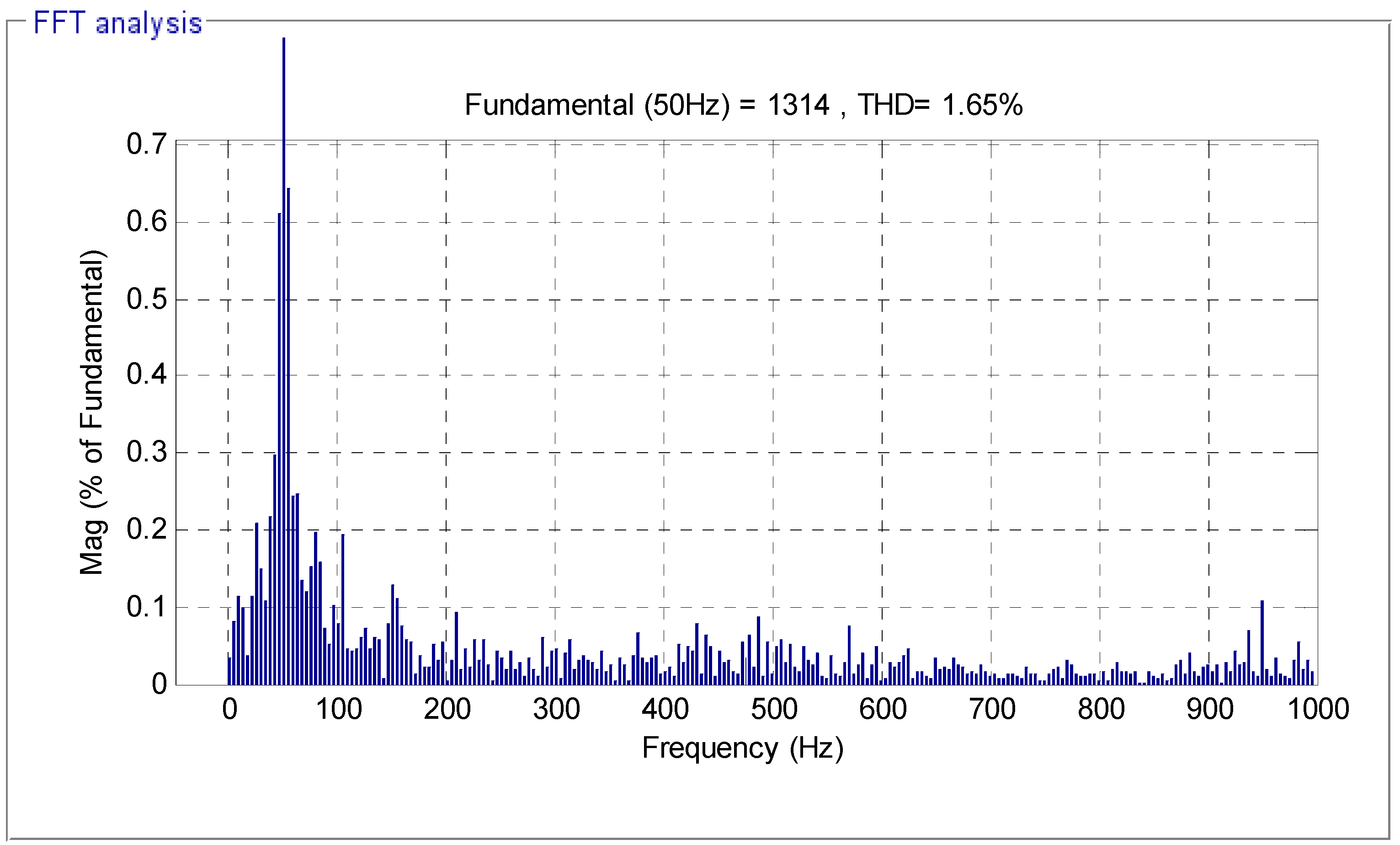
| THD (%) | 1.65 | 0.13 |
| Settling time (ms) | High | Medium |
| Active power ripple (W) | Around 2000 | Around 800 |
| Sensitivity to parameter change | High | Medium |
| Overshoot (%) | Remarkable ≈ 12% | Neglected |
| Simplicity of converter and filter design | Simple | Simple |
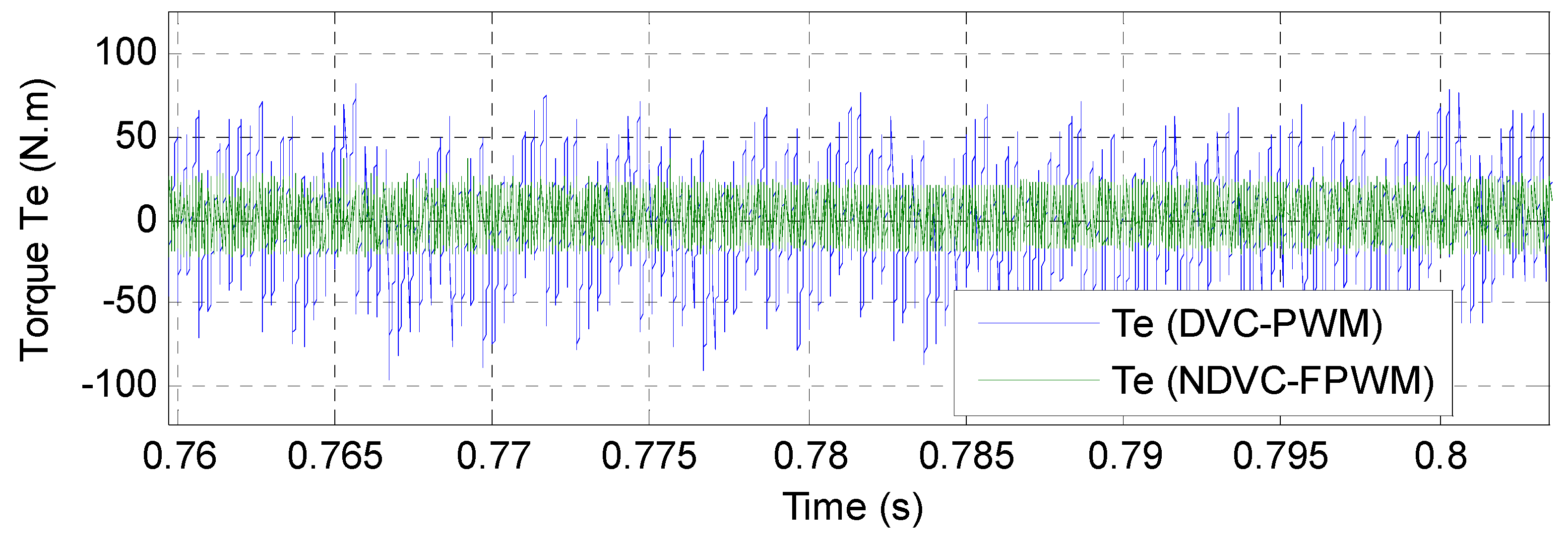
| Torque: ripple (N.m) | Around 170 | Around 50 |
| Rise Time (s) | High | Medium |
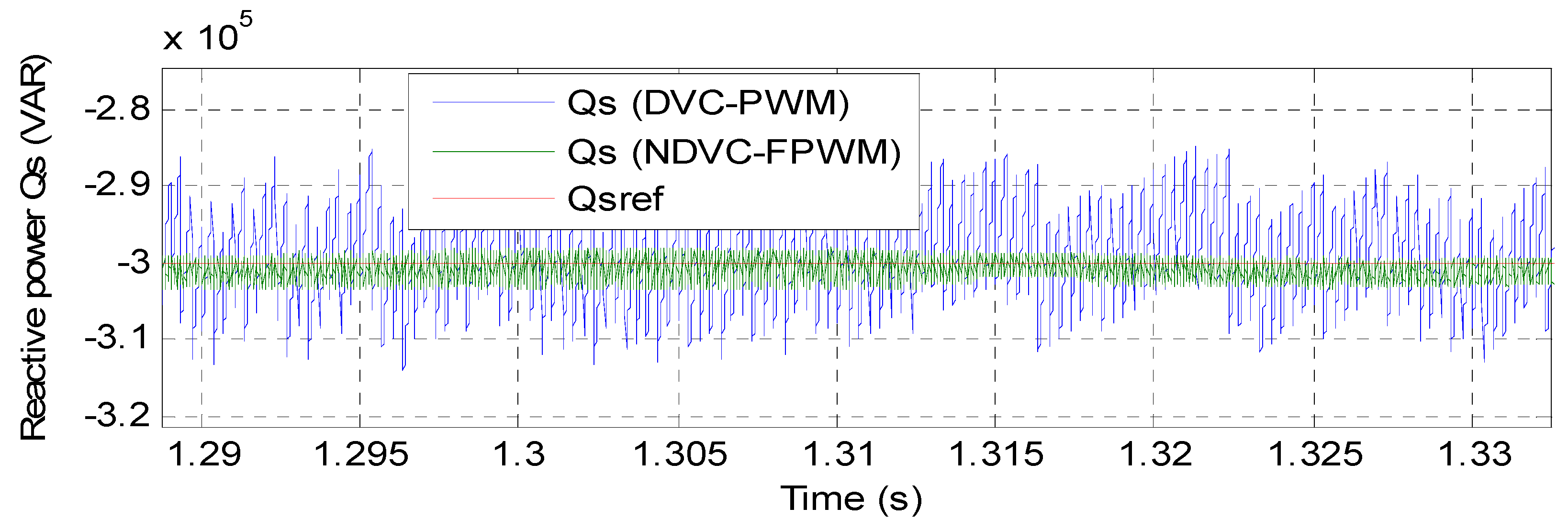
| Reactive power ripple (VAR) | Around 1700 | Around 980 |
| Simplicity of calculations | Simple | Rather complicated |
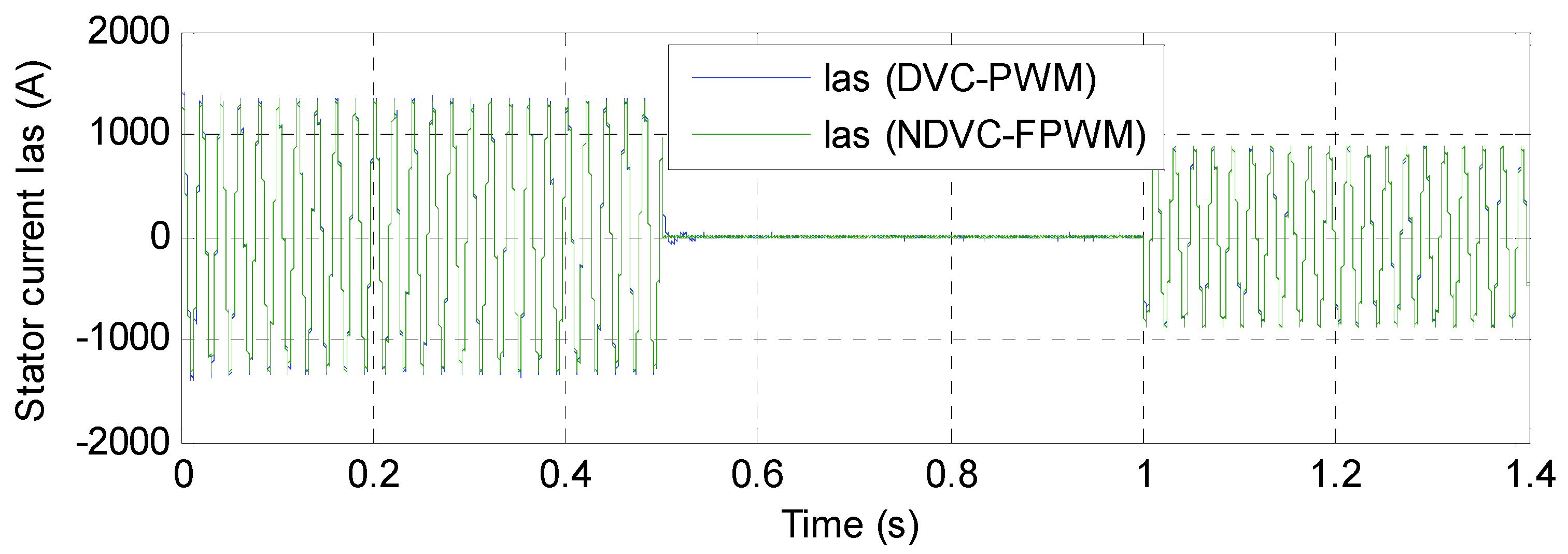
| Stator current: ripple (A) | Around 100 | Around 15 |
| Quality of stator current | Acceptable | Excellent |
| Improvement of transient performance | Good | Excellent |
| Response Time | ||||
|---|---|---|---|---|
| Torque | Reactive Power | Active Power | ||
| Proposed technique: NDVC-FPWM | 1.78 ms | 8.5 ms | 1.78 ms | |
| Ref. [60] | Neuro-second order sliding mode control (NSOSMC) | 5 ms | 9 ms | 5 ms |
| Direct power control (DPC) | 18 ms | 17 ms | 18 ms | |
| Reference | Strategy | THD (%) |
|---|---|---|
| Ref. [61] | DTC control | 2.57 |
| Ref. [47] | FOC control | 3.7 |
| Ref. [55] | Classical DTC method | 6.70 |
| Fuzzy DTC method | 2.40 | |
| Ref. [62] | DPC with PI controllers | 0.43 |
| Ref. [63] | 12 sectors DPC(12-DPC) control | 0.40 |
| Ref. [64] | Fuzzy SMC method | 1.15 |
| Ref. [65] | SOSMC method | 3.13 |
| Ref. [66] | DPC control with STA controller | 1.66 |
| Ref. [67] | DVC control with synergetic sliding mode controller | 0.50 |
| Ref. [68] | Integral sliding mode control (ISMC) | 9.71 |
| Multi-resonant-based sliding mode controller (MRSMC) | 3.14 | |
| Ref. [69] | DPC with terminal synergetic controller | 0.25 |
| Ref. [70] | Two-level DTC control | 8.75 |
| Three-level DTC control | 1.57 | |
| Ref. [71] | Intelligent super twisting sliding mode controller | 0.52 |
| Proposed strategy | Traditional DVC control | 1.65 |
| NDVC-FPWM control | 0.13 |
Publisher’s Note: MDPI stays neutral with regard to jurisdictional claims in published maps and institutional affiliations. |
© 2021 by the authors. Licensee MDPI, Basel, Switzerland. This article is an open access article distributed under the terms and conditions of the Creative Commons Attribution (CC BY) license (https://creativecommons.org/licenses/by/4.0/).
Share and Cite
Benbouhenni, H.; Bizon, N. Advanced Direct Vector Control Method for Optimizing the Operation of a Double-Powered Induction Generator-Based Dual-Rotor Wind Turbine System. Mathematics 2021, 9, 2403. https://doi.org/10.3390/math9192403
Benbouhenni H, Bizon N. Advanced Direct Vector Control Method for Optimizing the Operation of a Double-Powered Induction Generator-Based Dual-Rotor Wind Turbine System. Mathematics. 2021; 9(19):2403. https://doi.org/10.3390/math9192403
Chicago/Turabian StyleBenbouhenni, Habib, and Nicu Bizon. 2021. "Advanced Direct Vector Control Method for Optimizing the Operation of a Double-Powered Induction Generator-Based Dual-Rotor Wind Turbine System" Mathematics 9, no. 19: 2403. https://doi.org/10.3390/math9192403
APA StyleBenbouhenni, H., & Bizon, N. (2021). Advanced Direct Vector Control Method for Optimizing the Operation of a Double-Powered Induction Generator-Based Dual-Rotor Wind Turbine System. Mathematics, 9(19), 2403. https://doi.org/10.3390/math9192403