Abstract
This paper presents the design and realization of a compact frequency reconfigurable antenna for multiband wireless applications. The antenna can operate at overall eight different bands in four dual-band modes. A slot in the radiator and defected ground structure are utilized to achieve a compact size, while PIN diodes are used for frequency reconfigurability in the proposed antenna. The antenna shows broad bandwidth in each operating frequency and has a compact size of 18 mm × 18 mm × 1.524 mm. Moreover, stable radiation patterns and a high value of efficiency make it a potential candidate for various wireless applications. Furthermore, to demonstrate the worth of this work, its performance is compared with state-of-the-art designs reported for similar applications.
1. Introduction
In the last decade, reconfigurable antenna gains considerable attention of researchers due to an exponential increase in the number of users connected to the internet [1,2]. Reconfigurable antennas provide the ability to switch polarization, frequency, and pattern as per user’s demand [3,4,5,6]. Frequency reconfigurable antennas are preferred over multiband and wideband antennas because they lead to a better solution against the band congestion problems [7,8]. In the literature, researchers have utilized PIN diodes, radio frequency microelectromechanical systems (RF MEMS), optical switches, and varactors diodes to achieve frequency reconfigurability in antennas [9].
The PIN diodes are widely used in frequency reconfigurable antennas due to the ease of switching between different frequencies by merely controlling the biasing voltage [10]. Typically, diodes are used to manage the current path in an antenna geometry to achieve multiband operations [11,12,13,14,15]. In [11,12], three PIN diodes are placed in the defected ground to switch between three different frequencies. Although reported antennas have compact sizes, the number of frequency bands covered by the antennas are not sufficient for multiband applications. Another tri-band frequency reconfigurable antenna is presented in [13], where a single diode is placed in the monopole antenna’s radiator. The antenna can switch between dual-band and single-band operating modes but is physically large.
In [14], the hexa-band frequency reconfigurable antenna shows a compact size with dual operational mode. Moreover, octa-band antennas are also presented to support various frequency bands [15,16]. The design reported in [16] has the advantage of compact size compared to that reported in [15], whereas the design achieves dual and tri-band operational mode by utilizing a smaller number of diodes. The summary mentioned above of literature suggests that a compact antenna having a more significant number of frequency bands while using a minimum number of diodes is still a design challenge for researchers. Therefore, to overcome these challenges, a novel frequency reconfigurable antenna is presented in this paper. The significant contributions of this work are as follows:
- The proposed antenna has a compact size when compared with designs reported in the literature.
- The antenna geometry comprises a simple structure, which minimizes the fabrication losses.
- By utilizing only two diodes, the antenna resonates at eight different frequencies having four different dual modes.
2. Antenna Structure and Design Methodology
2.1. Antenna Structure
The front, back, and side views of the proposed frequency reconfigurable antenna are depicted in Figure 1a–c, with all essential dimensions labeled by different alphabets. The antenna geometry is engraved on the top side of ROGERS TMMR-4, having a dielectric constant () of 4.2 and loss tangent () 0.002. The bottom side of the antenna consists of the Defected Ground Structure (DGS). The standard copper cladding of 0.035 mm is used for both the radiator and the DGS.
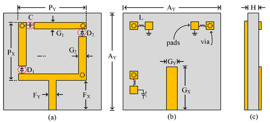
Figure 1.
Proposed frequency reconfigurable antenna (a) top-view (b) bottom-view (c) side-view.
2.2. Antenna Design Methodology
Monopole antenna, owing to the advantage of a wider band compared to other types of antennas, is designed in the first step [17]. The length of the monopole antenna can be calculated using the analytical equations given in [18].
where c is the speed of light which is 3 × 10⁸ ms−1, is the central resonating frequency, which is given by:
where is the guided wavelength and is the effective dielectric constant which is given by:
where is the dielectric constant of the substrate, is the width of the monopole, and H is the thickness of the substrate.
The monopole’s optimized length at the operating frequency of 3.5 GHz is found to be 18 mm, which is approximately equal to , as shown in Figure 2. The overall dimensions of the antenna are: 26 mm × 2 mm × 1.524 mm. The reflection coefficients of the proposed antenna is plotted in Figure 3. To further miniaturize the conventional monopole’s dimension, a rectangular slot of dimension is inserted in the radiator—this new antenna is referred to as Prototype-II. The introduction of this slot increases the antenna’s effective area and thus shifts the resonance toward the lower side. Moreover, the introduction of this slot also introduces an upper band, as depicted in Figure 3.
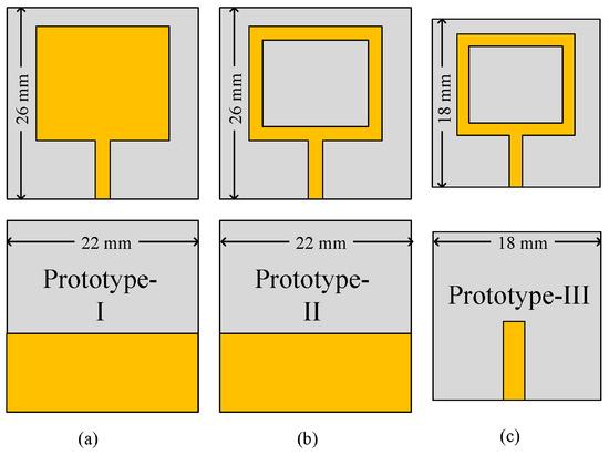
Figure 2.
Design evolution of the proposed antenna.
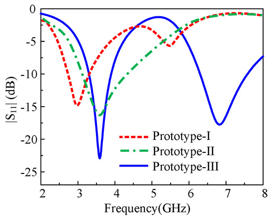
Figure 3.
The simulated reflection coefficient of three different prototypes for the proposed antenna design.
To move the resonance frequency back to 3.5 GHz, the dimensions of the antenna are optimized. After a detailed parametric study, optimum dimensions are used in the Prototype-III, which are shown in Figure 2c. The Prototype-III resonates at 3.5 GHz. It can be seen from Figure 2a–c that this prototype has a physical area of 324 mm2, which is 44% smaller compared to the conventional monopole antenna that has an area of 572 mm2.
In the last step, two RF-PIN diodes modeled as SC-79 by Skyworks were utilized to achieve frequency reconfiguration. The lumped elements were used to design an equivalent model of PIN diode, whose values can be found using [19]. The positions of the diodes are optimized to get desired results while a desired DC block 100 pF capacitor is also used to physically disconnect the upper part of the radiator, as shown in Figure 1a. The optimized dimensions of the proposed antenna are as follows: mm; mm; mm; mm; mm; mm; mm; mm; mm; mm; mm; pF.
3. Results and Discussion
3.1. Simulated and Measurement Setup
Usually, antennas can be analyzed using the full-wave method or approximation method based on simplifying assumptions. In full-wave, electromagnetic solutions include all the possible electromagnetic solutions within a boundary condition. In contrast, the approximation method cannot consider surface waves and mutual coupling since it does not enforce boundary conditions. Various software solutions for antenna design, including a comparison of packages, tools, techniques, and algorithms for different design challenges, have been reported thoroughly [20]. For broadband results in high frequencies, full-wave time-domain methods are more accurate. For accurate characterization of the proposed antenna, we modeled 3D structure of the antenna, and its impedance and radiation characteristics are computed by employing finite-integration time-domain electromagnetic simulator CST. We chose a transient time-domain solver with a hexahedral mesh type was selected with an accuracy level of −40 dB. The PIN diodes were realized using its equivalent lump lumped elements. Furthermore, to minimize the connector’s effect on antenna performance, commercially available SMA is modeled and used at the antenna feed for numerical analysis. The equivalent electrical model of the PIN-diode utilized for simulation is presented in Figure 4. For the ON-state, the PIN-diode behaves like a series combination of inductor and resistor. While for OFF-state, the diode acts like a series combination of an inductor with a parallel combination of resistor and capacitor, as depicted in Figure 4 a,b, respectively. For ease of understanding, OFF-state is represented by ‘0’ while diode On-state is meant by ‘1’. Figure 5 illustrates the fabricated prototype of the proposed antenna utilized for measurement purposes. Vector Network Analyzer (VNA) having model no. E5063A with a range of 500 MHz to 18 GHz, by Keysight Tech., was utilized to measure the return loss of the proposed work. A broadband horn antenna (1–18 GHz) was used for the measurements of far-field parameters, which means radiation patterns and gain.
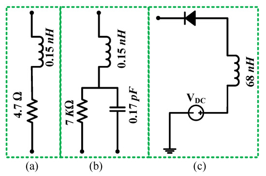
Figure 4.
Equivalent model of diode for (a) ON-state (b) OFF-state (c) biasing circuit.
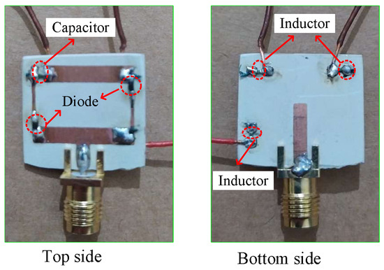
Figure 5.
Fabricated prototype of the proposed antenna design.
3.2. Reflection Coefficient
Figure 6 presents the comparison of the magnitude of the proposed antenna’s reflection coefficient for various switching states. For case-00, the antenna resonates at two frequencies of 4.6 GHz and 7.2 GHz with respective predicted bandwidth of 1020 MHz and 840 MHz, as depicted in Figure 6a, while the measured values show the impedance bandwidth of 1390 MHz and 1010 MHz for resonating frequency of 4 GHz and 6.85 GHz, respectively. It could also be seen from Figure 6a that for case-01, the antenna resonates at 4.1 GHz and 7 GHz with respective impedance bandwidths of 760 MHz and 1090 MHz. On the other, the measured value shows the resonating frequencies of 4 GHz and 6.85 GHz having individual bandwidth of 870 MHz and 1210 MHz, as depicted in Figure 6a.
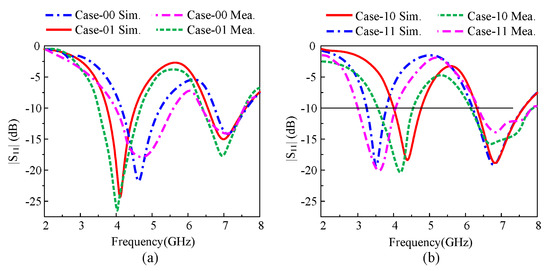
Figure 6.
The comparison between measured and simulated reflection coefficient for various switching cases; (a) Case-00, Case-01 (b) Case-10, Case-11.
It could be observed from Figure 6b that antenna starts resonating at 4.4 GHz and 6.92 GHz for case-10, where the antenna exhibits the simulated bandwidths of 810 MHz and 1400 MHz while measured impedance bandwidths were observed to be 1100 MHz and 1520 MHz, respectively. At last, for case-11, the simulated |S11| > −10 dB bandwidths were observed to be 560 MHz and 1350 MHz at the resonating frequencies of 3.5 GHz and 6.87 GHz, respectively. The measured results show that the antenna exhibits impedance bandwidths of 920 MHz and 1240 MHz for respective resonating frequencies of 3.55 GHz and 7 GHz, as depicted in Figure 6b. In general, predicated and measured return loss show a strong agreement between each other, while a little discrepancy was due to fabrication and measurement tolerance.
3.3. Far-Field Analysis
Figure 7a–f depicts the comparison among predicted and measured radiation patterns at the various frequencies. The antenna exhibits an omnidirectional radiation pattern in principle E-plane for lower passband frequencies, while a slightly distorted omnidirectional radiation pattern was observed for higher passband frequencies, as depicted in Figure 7b,f. Regarding principle H-plane , the antenna exhibits an 8-shaped bidirectional radiation pattern for all selected resonating frequencies. is observed in E-plane. In general, a good agreement was observed between simulated and measured results for all selected frequencies, as depicted in Figure 7.
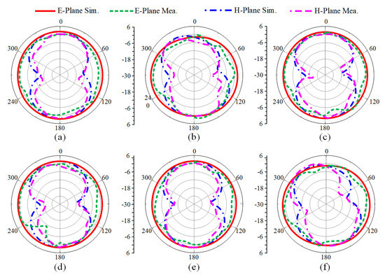
Figure 7.
Simulated and measured radiation pattern (a) case-00 (b) case-00 (c) case-01 (d) case-10 (e) case-11 (f) case-11.
Figure 8 compares simulated and measured peak gain of the proposed antenna along with numerically calculated radiation efficiency. Figure 8 shows that the peak gain of antenna varies from 2 to 3 dBi in the lower pass band in all switching states while the gain varies from 3 to 4 dBi in the upper passband. The antenna’s measured peak gain for possible switching states of diode was also in good agreement with simulated results. The antenna exhibits an efficiency of more than 80% in both passbands, as depicted in Figure 8. Thus, a strong comparison between simulated and measured results of the antenna states its performance stability and makes it a potential candidate for compact devices requiring multiband reconfigurable antenna.
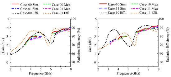
Figure 8.
Simulated and measured gain along with radiation efficiency.
3.4. Comparison with State-of-the-Art Work
Table 1 presents the comparison of presented work with recently reported antennas for similar applications. The proposed antenna offers more bands than reported antennas in [11,12,13,14] and the additional advantages of compact size. Compared to the work presented in [15,16], the number of operating bands are equal, but the proposed antenna offers a physically compact size. Thus, it can be deduced that the presented antenna overperforms the related works by providing a simple structure, compact size, and a large number of bands.

Table 1.
Performance comparison with existing works.
4. Conclusions
A compact frequency reconfigurable antenna operating in eight different frequencies in four dual-band modes is presented. The operating modes are controlled using two PIN diodes introduced in the radiating element. The proposed antenna is characterized by the good adaptation for all provided frequencies, higher radiation efficiency values in the whole range of frequencies, and similar radiation patterns in all diode cases, making it a promising candidate for various wireless applications.
Author Contributions
Conceptualization, A.G. and W.A.A.; methodology, N.H.; software, A.G., W.A.A.; validation, N.H., X.J.-L.; investigation, N.H.; resources, A.G., N.H.; writing—original draft preparation, A.G., W.A.A.; writing—review and editing, N.H., X.J.-L.; supervision, X.J.-L.; funding acquisition, A.G., N.H. All authors have read and agreed to the published version of the manuscript.
Funding
This research received no external funding.
Institutional Review Board Statement
Not Applicable.
Informed Consent Statement
Not Applicable.
Data Availability Statement
Data is contained within the article.
Conflicts of Interest
The authors declare no conflict of interest.
References
- Lim, S.; Yoon, Y.J. Wideband-Narrowband Switchable Tapered Slot Antenna for Breast Cancer Diagnosis and Treatment. Appl. Sci. 2021, 11, 3606. [Google Scholar] [CrossRef]
- Qin, P.; Wang, L.; Liu, T.Y.; Wang, Q.Y.; Fu, J.H.; Huang, G.L.; Gui, L.; Liu, J.; Deng, Z.S. The Design and Manufacturing Process of an Electrolyte-Free Liquid Metal Frequency-Reconfigurable Antenna. Sensors 2021, 21, 1793. [Google Scholar] [CrossRef] [PubMed]
- Ghaffar, A.; Li, X.J.; Awan, W.A.; Naqvi, A.H.; Hussain, N. A Flexible and Pattern Reconfigurable Antenna with Small Dimensions and Simple Layout for Wireless Communication Systems Operating over 1.65–2.51 GHz. Electronics 2021, 10, 601. [Google Scholar] [CrossRef]
- Naqvi, A.H.; Lim, S. A beam-steering antenna with a fluidically programmable metasurface. IEEE Trans. Antennas. Propag. 2019, 67, 3704–3711. [Google Scholar] [CrossRef]
- Naqvi, A.H.; Lim, S. Microfluidically polarization-switchable metasurfaced antenna. IEEE Antennas Wirel. Propag. Lett. 2018, 17, 2255–2259. [Google Scholar] [CrossRef]
- Ghaffar, A.; Li, X.J.; Awan, W.A.; Nazeri, A.H.; Hussain, N.; Seet, B.C. Compact multiband multimode frequency reconfigurable antenna for heterogeneous wireless applications. Int. J. Microw. Comput. Eng. 2021, 31, e22659. [Google Scholar]
- Naqvi, S.A.; Khan, M.S. Design of a miniaturized frequency reconfigurable antenna for rectenna in WiMAX and ISM frequency bands. Microw. Opt. Technol. Lett. 2018, 60, 325–330. [Google Scholar] [CrossRef]
- Ahmad, A.; Arshad, F.; Naqvi, S.I.; Amin, Y.; Tenhunen, H.; Loo, J. Flexible and compact spiral-shaped frequency reconfigurable antenna for wireless applications. IETE J. Res. 2020, 6, 22–29. [Google Scholar] [CrossRef]
- Smida, A.; Iqbal, A.; Selmi, M.; Althuwayb, A.A.; Mallat, N.K. Varactor diode-based dual-band frequency tunable multiple-input multiple-output antenna. Int. J. Microw. Comput. Eng. 2021, 31, e22519. [Google Scholar]
- Hussain, N.; Awan, W.A.; Naqvi, S.I.; Ghaffar, A.; Zaidi, A.; Naqvi, S.A.; Iftikhar, A.; Li, X.J. A Compact Flexible Frequency Reconfigurable Antenna for Heterogeneous Applications. IEEE Access 2020, 8, 173298–173307. [Google Scholar] [CrossRef]
- Borhani, M.; Rezaei, P.; Valizade, A. Design of a reconfigurable miniaturized microstrip antenna for switchable multiband systems. IEEE Antennas. Wirel. Propag. Lett. 2015, 3, 822–825. [Google Scholar] [CrossRef]
- Han, L.; Wang, C.; Chen, X.; Zhang, W. Compact frequency-reconfigurable slot antenna for wireless applications. IEEE Antennas. Wirel. Propag. Lett. 2016, 15, 1795–1798. [Google Scholar] [CrossRef]
- Ullah, S.; Hayat, S.; Umar, A.; Ali, U.; Tahir, F.A.; Flint, J.A. Design, fabrication and measurement of triple band frequency reconfigurable antennas for portable wireless communications. AEU Int. J. Electron. Commun. 2017, 81, 236–242. [Google Scholar] [CrossRef]
- Shah, A.; Hayat, S.; Basir, A.; Zada, M.; Shah, S.A.A.; Ullah, S. Design and analysis of a hexa-band frequency reconfigurable antenna for wireless communication. AEU Int. J. Electron. Commun. 2019, 98, 80–88. [Google Scholar] [CrossRef]
- Abdulraheem, Y.I.; Oguntala, G.A.; Abdullah, A.S.; Mohammed, H.J.; Ali, R.A.; Abd-Alhameed, R.A.; Noras, J.M. Design of frequency reconfigurable multiband compact antenna using two PIN diodes for WLAN/WiMAX applications. IET Microwaves Antennas Propag. 2017, 11, 1098–1105. [Google Scholar] [CrossRef] [Green Version]
- Iqbal, A.; Smida, L.F.; Abdulrazak, O.A.; Saraereh, N.K.; Mallat, I.; Elfergani, S.K. Low-profile frequency reconfigurable antenna for heterogeneous wireless systems. Electronics 2019, 8, 976. [Google Scholar] [CrossRef] [Green Version]
- Hussain, N.; Jeong, M.; Park, J.; Rhee, S.; Kim, P.; Kim, N. A compact size 2.9–23.5 GHz microstrip patch antenna with WLAN band-rejection. Microw. Opt. Technol. Lett. 2019, 61, 1307–1313. [Google Scholar] [CrossRef]
- Stutzman, W.L.; Thiele, G.A. Antenna Theory and Design; John Wiley & Sons: Hoboken, NJ, USA, 2013. [Google Scholar]
- Skyworks Solution. Available online: www.skyworksinc.com (accessed on 20 April 2020).
- Grout, V.; Akinsolu, M.O.; Liu, B.; Lazaridis, P.I.; Mistry, K.K.; Zaharis, Z.D. Software Solutions for Antenna Design Exploration: A Comparison of Packages, Tools, Techniques, and Algorithms for Various Design Challenges. IEEE Antennas Propag. Mag. 2019, 61, 48–59. [Google Scholar] [CrossRef]
Publisher’s Note: MDPI stays neutral with regard to jurisdictional claims in published maps and institutional affiliations. |
© 2021 by the authors. Licensee MDPI, Basel, Switzerland. This article is an open access article distributed under the terms and conditions of the Creative Commons Attribution (CC BY) license (https://creativecommons.org/licenses/by/4.0/).