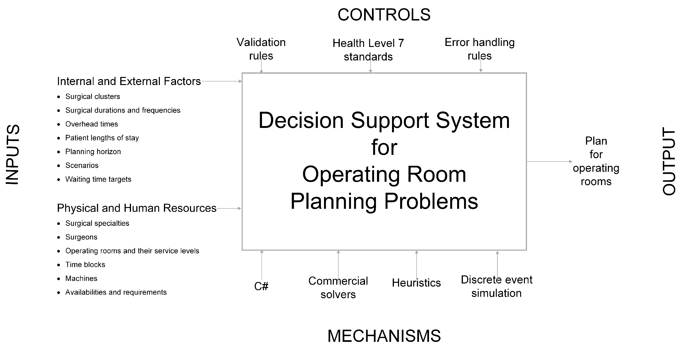
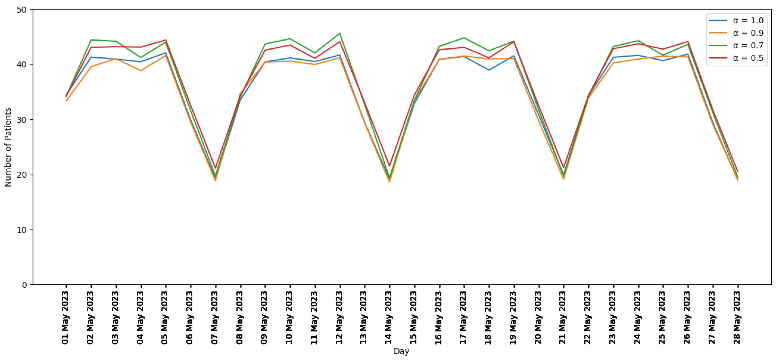
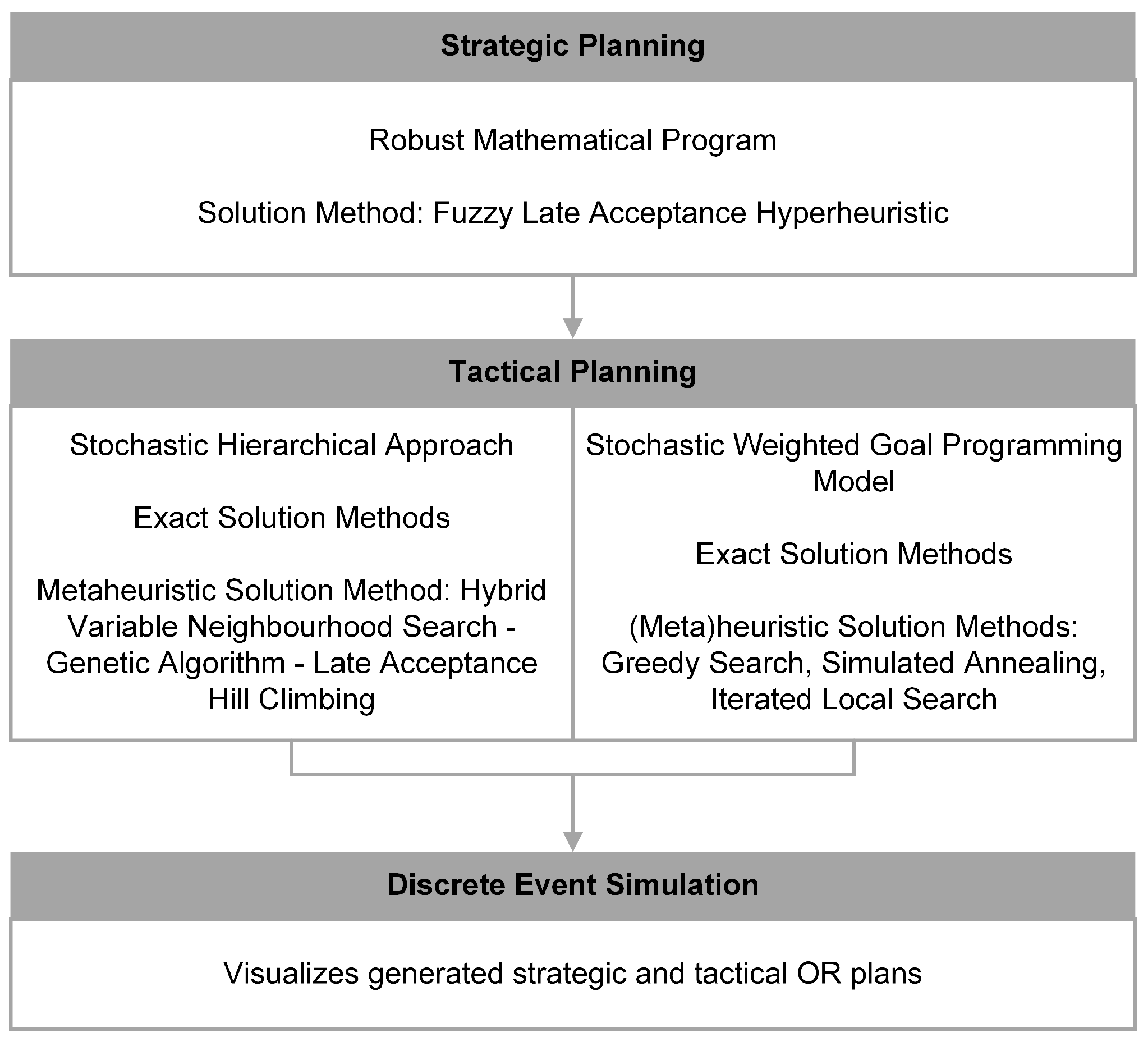
A four-phase iterative system development lifecycle (SDLC) model is used to design the DSS. The phases are system initiation, system requirements, system design, and system construction.
2.2.2. System Requirements
The second phase involves considering the requirements of the system. After analyzing the cause and effects associated with the problem, the system requirements are identified and prioritized. Use case models that take relevant actors into account are then developed. Finally, the logical data flows and designs are explained.
Problem Analysis
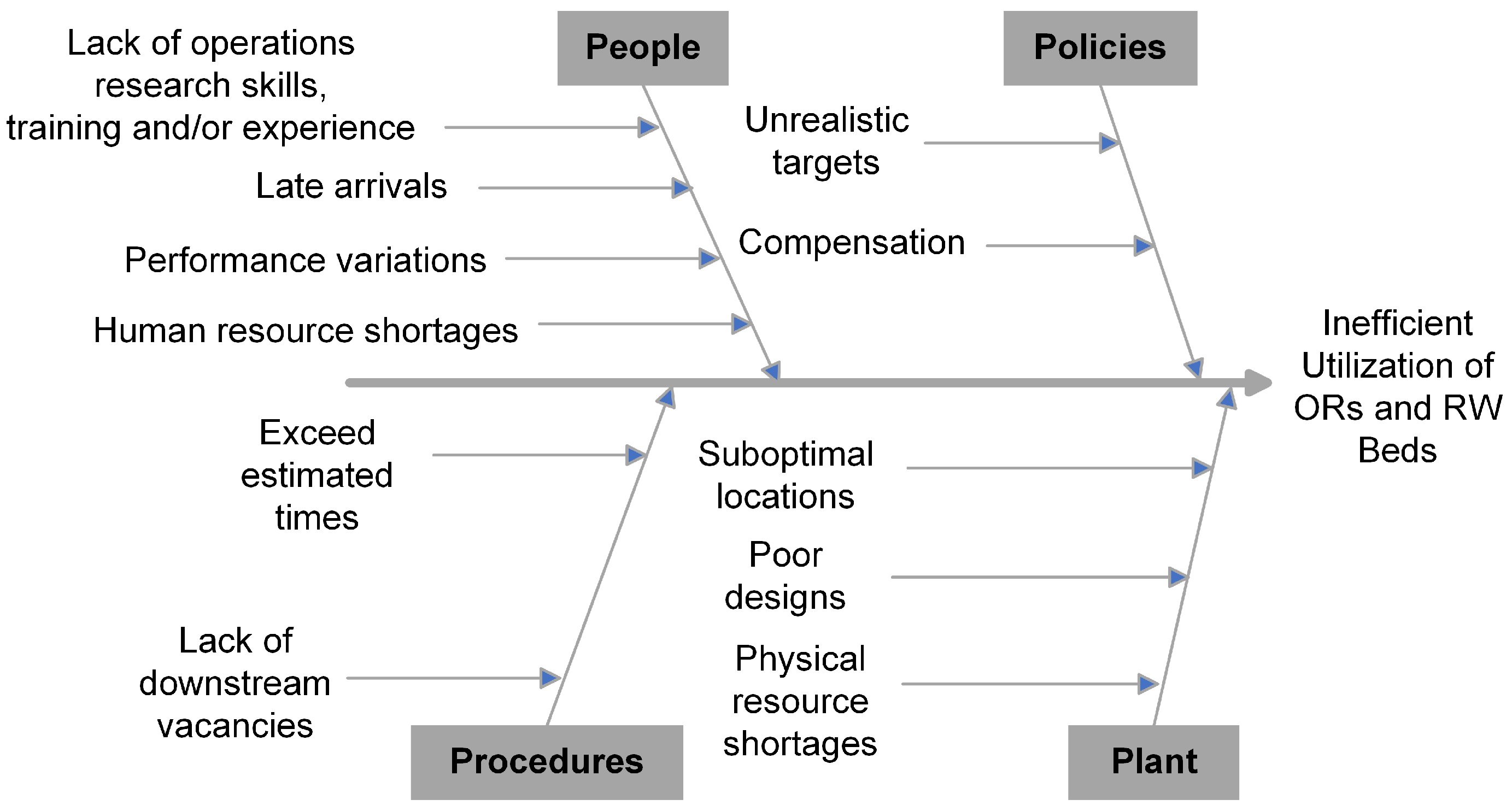
Cause and effect analysis is applied to the system of ORs and RW beds.
Figure 3 is the corresponding Ishikawa diagram.
Potential causes are classified into four categories that all start with the letter P: people, policies, procedures, and plant.
In the people category, several different groups could be responsible: hospital managers, OR planners, patients, surgeons, and other workers at the hospital. Hospital managers and OR planners may not have training and/or experience in operations research. This could prevent them from properly utilizing mathematical programming, solution methods, and DES models to generate and visualize OR plans and schedules. Patients could arrive late, which could delay surgery start times. There could be performance variations between surgeons. This could be problematic if OR plans and schedules were generated with the assumption that all surgeons perform equally well. Shortages of human resources, including hospital managers, OR planners, surgeons, and other workers at the hospital, could also cause performance issues in the hospital.
In the policies category, there are two potential causes. Firstly, targets for waiting times, number of patients, and number of hours for surgeries might be unrealistic. This would result in the creation of plans and schedules that do not use the ORs and RW beds efficiently. Secondly, surgeons in some jurisdictions get extra compensation if they perform surgeries after certain times on weekdays and at any times on weekends. These compensation policies could prevent the ORs from being used at night and on weekends.
In the procedures category, there also are two potential causes. Firstly, each procedure has an estimated time, but actual procedure times could exceed these estimated times. This could delay subsequent surgeries. Secondly, there could be a lack of vacancies in downstream units, including RW beds. This could cause surgeries to be cancelled or delayed.
Finally, in the plant category, there are three potential causes. Firstly, machines required for surgeries could be assigned to suboptimal locations. Secondly, ORs could be designed poorly. This could cause surgeries to have longer durations. Finally, there could be shortages of physical resources, including ORs and RW beds. This could prevent surgeries from happening.
The effect of these potential causes is that resources in the hospital, including ORs and RW beds, are not used efficiently.
Prioritization of System Requirements
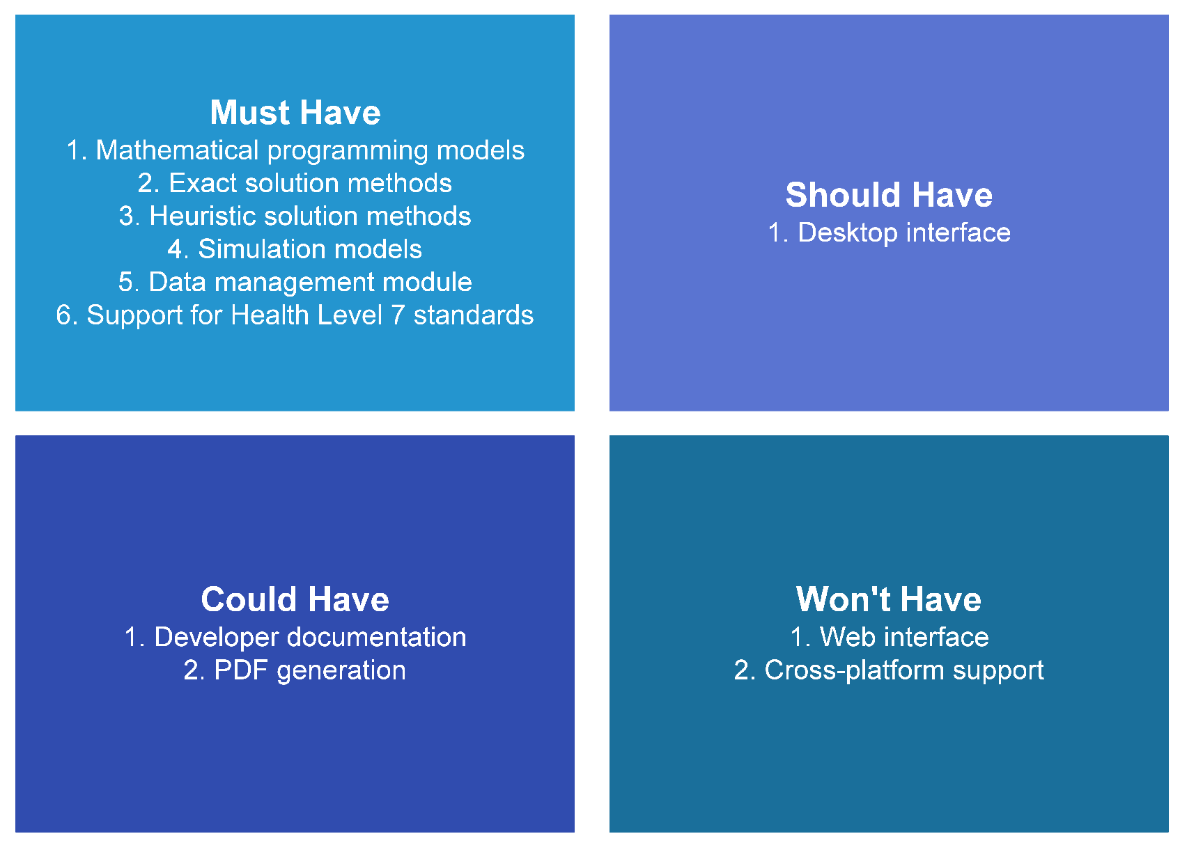
As shown in
Figure 4, MoSCoW analysis (must have, should have, could have, and will not have) is used to prioritize the requirements of the system.
In the must have category, there are several requirements. Firstly, the system must have mathematical programs that generate strategic and tactical OR plans. Secondly, the system must have exact and heuristic solution methods in order to obtain solutions to these mathematical programs. Thirdly, it must have simulation models that visualize the generated plans. Next, the system must have a data management module that allows the user to create, read, update, and delete information. Finally, the system must have support for HL7 standards in order to allow for interoperability with other information systems in the hospital.
In the should have category, there is one requirement. The system should have a desktop interface that allows the user to easily utilize the mathematical programs, solution methods, and DES models.
In the could have category, there are two requirements. Firstly, there could be development documentation that explains how the underlying code works. This is low priority because the development team is small. Secondly, the system could have the ability to generate PDF versions of the generated OR plans. Because open source PDF generation packages only seem to work with older versions of .NET, this feature is low priority.
In the will not have category, there are two requirements. Firstly, a web interface would allow the system to be used from any networked location, but the system will only have a desktop interface. Because the DSS handles healthcare-related data, a web interface would introduce too many privacy risks. Secondly, there could be cross-platform (Windows, Linux, MacOS) support, but the system will only work on Windows. Although .NET has some cross-platform support, most of the available desktop interfaces are designed for Windows.
Actors
The system is used by and interacts with different actors. The four key actors are hospital management, an OR planner, surgical specialties, and surgeons. The entire hospital, including the ORs and downstream RW beds, is managed by a team. The OR planner uses the DSS to generate OR plans. A surgical specialty is a collection of surgeons who perform the same types of surgeries. Each surgeon belongs to a surgical specialty and uses the ORs to perform surgeries on patients.
Use Case Modelling
The system has four use cases:
Manage data: As shown in
Figure 2, input data are required to generate OR plans. In this use case, the data are created, read, updated, and/or deleted.
Exact solution: This use case involves using an exact solution method to generate an OR plan.
Heuristic solution: This instead generates an OR plan using a heuristic solution method.
Simulation: In this use case, a generated OR plan is visualized using DES.
In addition, there are four roles: primary system actor, primary business actor, external receiver actor, and external server actor. Primary system actors directly interact with and provide inputs to the system. Primary business actors directly benefit from outputs of the system. External receiver actors do not directly interact with the system but receive some benefit from outputs of the system. External server actors provide information to the system.
Table 6 provides relationships between the use cases, actors, and roles. In all four use cases, the OR Planner actor interacts with the system directly and is the primary system actor.
For the manage data use case, the OR Planner actor uses the system to create, read, update, and/or delete data. Because the Hospital Management actor may be required to submit data to government or other external entities, they are the primary business actor in this use case.
For the exact and heuristic solution use cases, the OR planner uses the system to generate an OR plan. The details of that plan are then sent to the external receiver actors. These are the surgeons and the surgical specialties to which they belong.
For the simulation use case, the OR plan is visualized for the OR Planning Actor.
Logical Data Flow Diagrams and Design
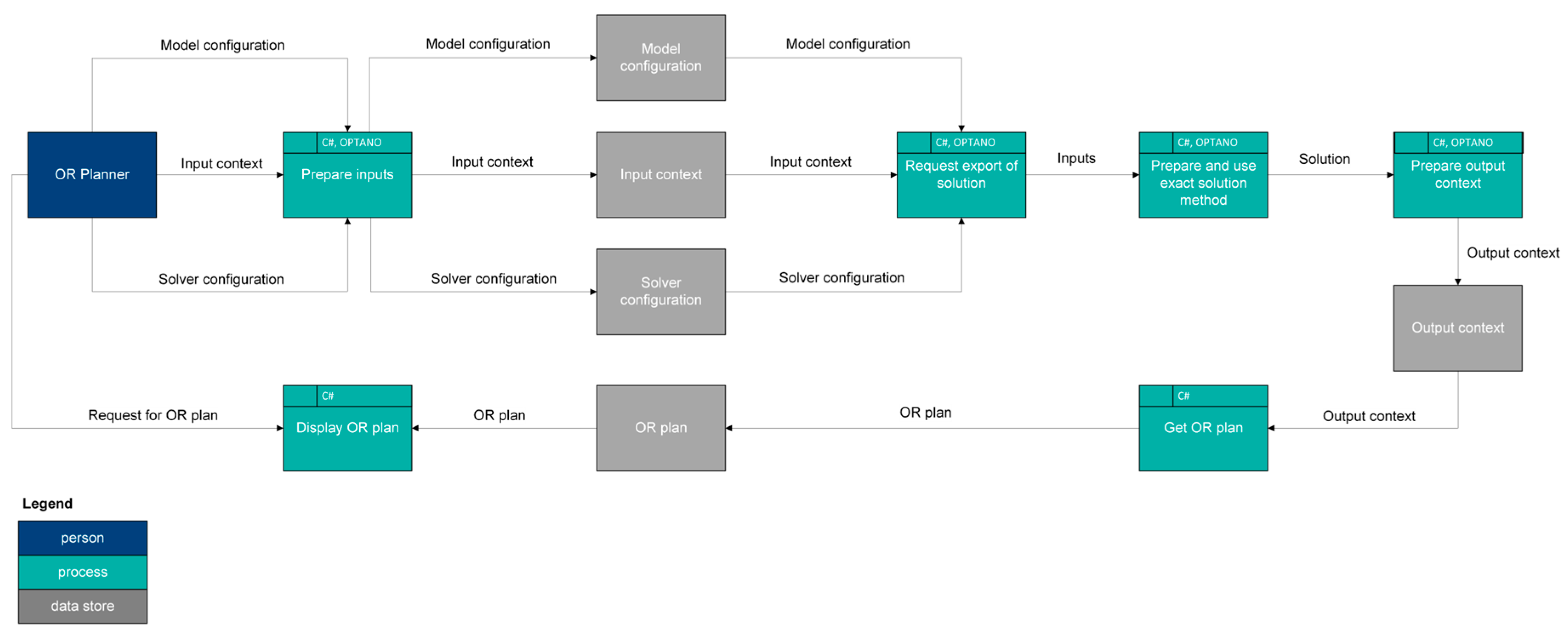
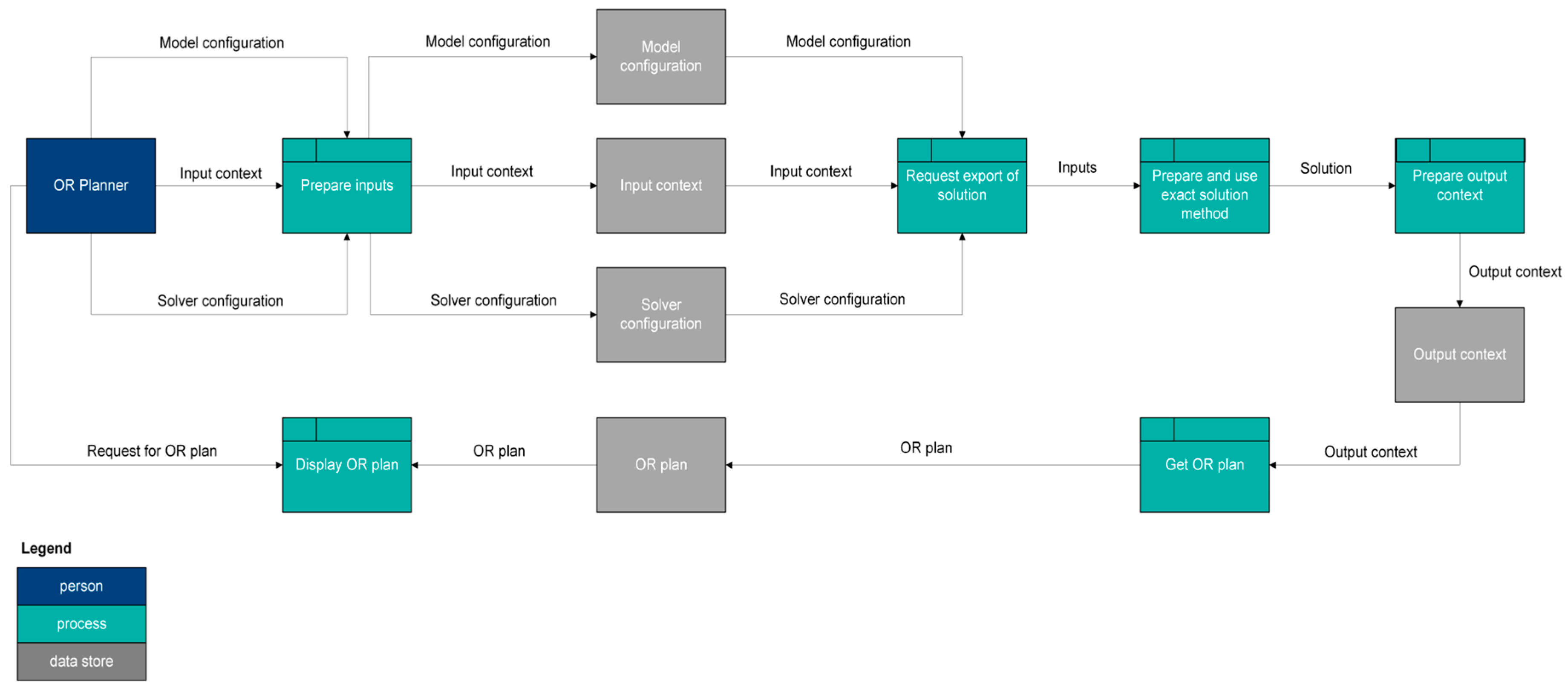
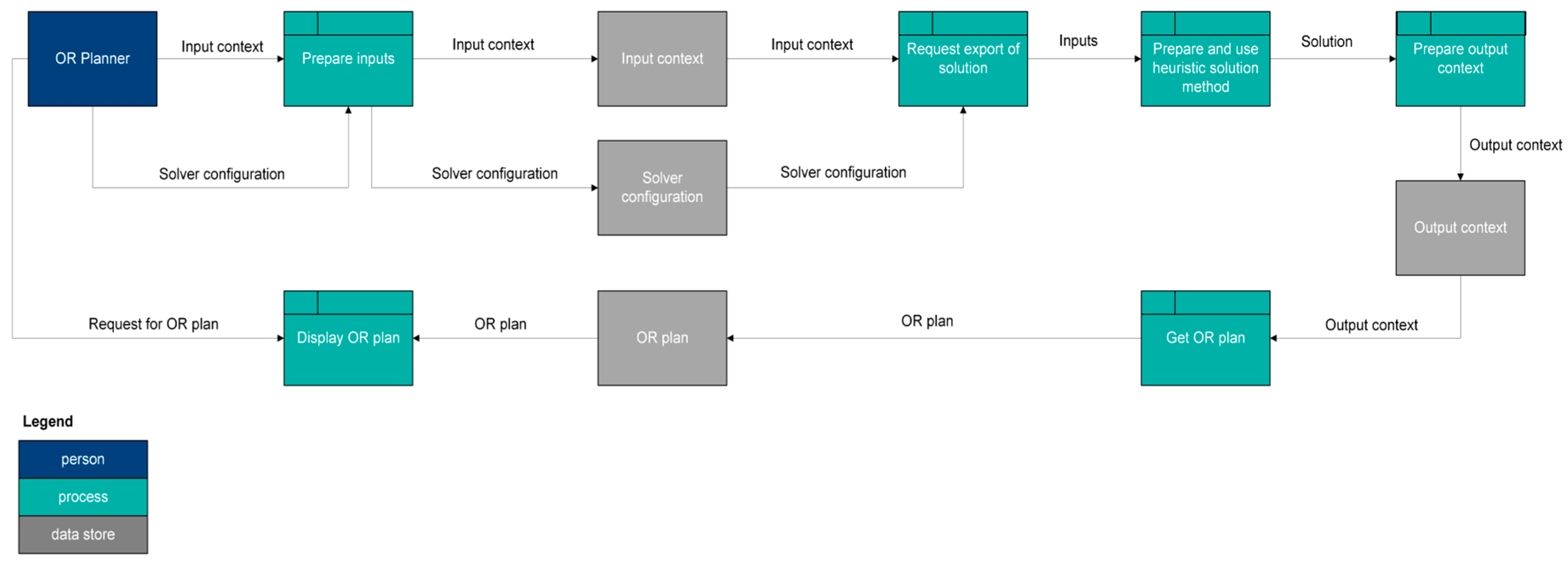
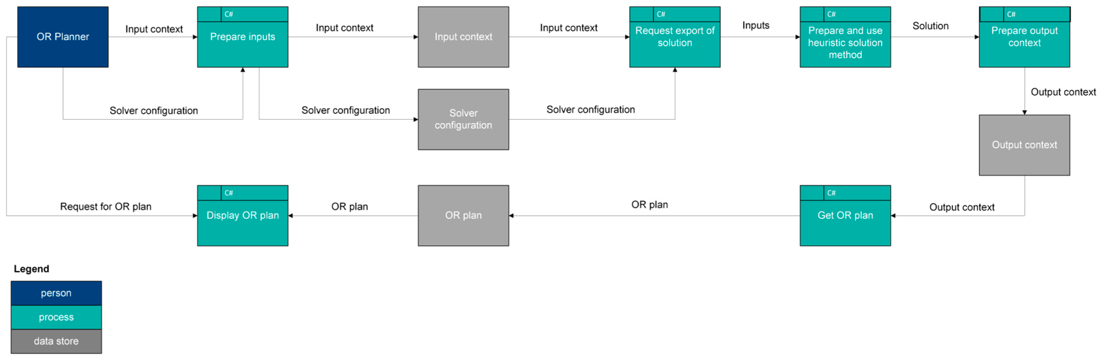
Figure 5 and
Figure 6 are logical data flow diagrams for using exact and heuristic solution methods, respectively, to generate OR plans.
For an exact solution method, the OR Planner actor provides the input preparation process an input context that contains the required input data and configurations for the model and commercial solver. The input context and two configurations are placed in their associated data stores. These three things then enter a process that requests a solution to be exported. Next, these inputs go to a process that prepares and uses an exact solution method. An output context preparation process then takes this solution and converts it into an output context, which is placed in its associated data store. A subsequent process then gets the OR plan and places it in its associated data store. The OR Planner actor then interacts with a process that displays the OR plan. This process obtains the generated OR plan from the relevant data store.
For a heuristic solution method, the logical data flows are almost exactly the same as the ones for an exact solution method. The difference is that a heuristic solution method does not need a model configuration.
2.2.4. System Construction
The fourth and final phase involves the construction of the system. In this section, the hierarchical diagramming model is first explained. Next, relevant diagrams from each level are provided. Finally, the core code components of the simulation system are explained.
Hierarchical Diagramming Model
A C4-like model, which has diagrams that are organized in a four-level hierarchy (context, container, component, and code) is used to document the construction of the DSS. The C4-like diagrams are from the perspective of the OR Planner actor.
In the code level of the hierarchy, the diagrams include unified modeling language (UML) class and sequence diagrams. The DSS includes a tool that automatically generates these diagrams from the source code. When the C# code is compiled, the Roslyn compiler generates an abstract syntax tree (AST). The diagram generation tool walks through the AST and identifies classes, methods, properties, calls to methods, and similar features. These are used to generate PlantUML code, which is then converted into UML diagrams.
C4-Like Diagrams and Construction of System
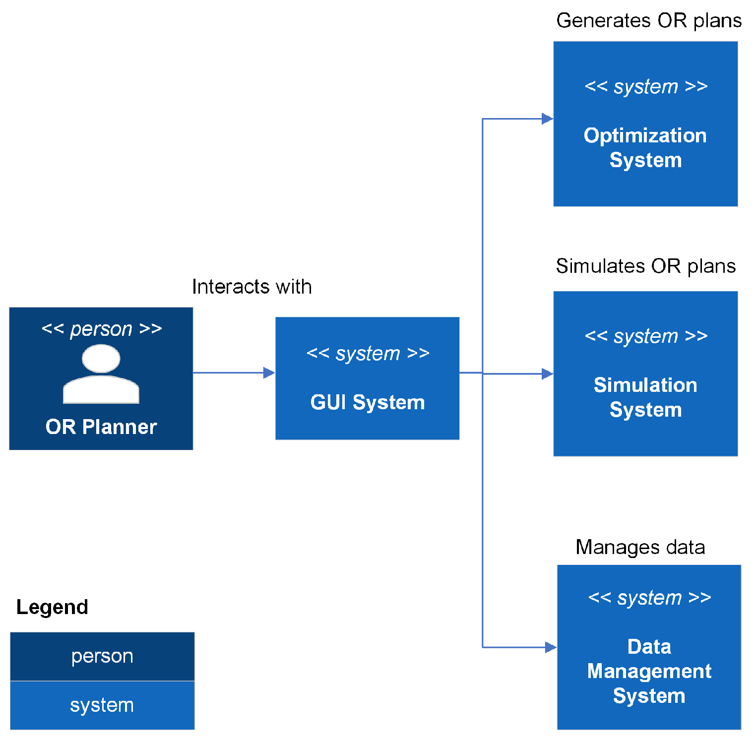
Figure 9 is a context diagram for the DSS. In addition to the GUI system that the OR Planner interacts with and a data management system, there are two other systems in the DSS: an optimization system and a simulation system. The optimization system contains exact and heuristic solution methods that solve mathematical programming models in order to generate OR plans. The simulation system enables the visualization of the generated OR plans.
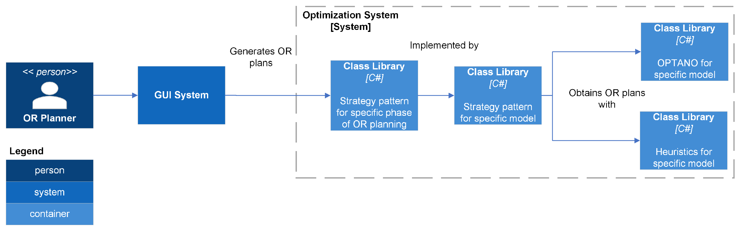
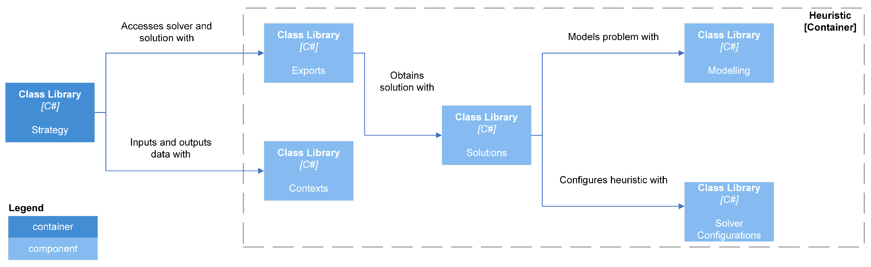
Figure 10 is a container diagram for the optimization system. For each specific phase of OR planning, there is an associated strategy pattern. For a given phase (e.g., strategic planning or tactical planning), one or more different mathematical models can be used to generate OR plans. For each model, there is a corresponding strategy pattern. A solution for a specific model can be obtained using either an exact (using the OPTANO mathematical programming API) or a heuristic solution method.
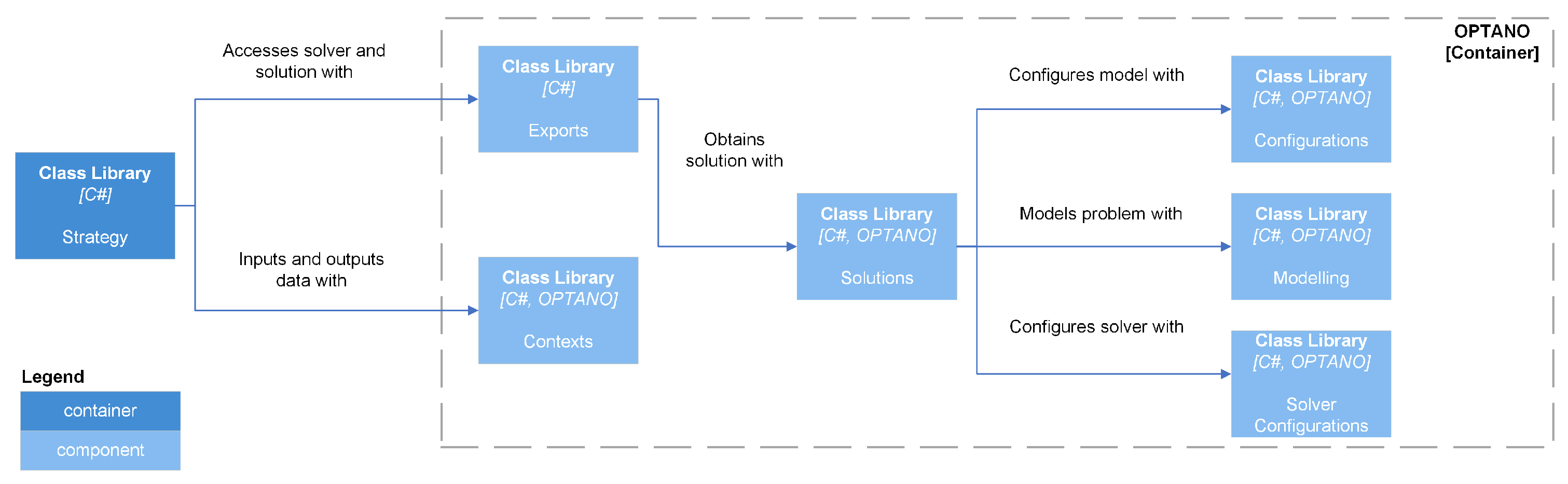
Figure 11 and
Figure 12 are component diagrams for exact and heuristic, respectively, solution methods. Each exact and heuristic solution method has an export class that accepts an input context containing data related to the OR planning problem and a solver configuration containing parameters used by the solver. In addition, the export class for an exact solution method requires a configuration for the OPTANO model. The export class creates a solution class, which generates a model and solves it, and then returns an output context that contains the OR plan.
Several different heuristic solution methods, including simulated annealing and iterated local search, are used [
54,
55,
56]. In addition, two of the newer heuristics implemented are a hybrid variable neighbourhood search-genetic algorithm heuristic and a fuzzy late acceptance hyperheuristic; both utilize late acceptance [
49,
50,
51,
52,
53].
BeVelS is a framework that allows the DSS to have a fully integrated simulation package. The name of the framework is derived from the names of the physics (BepuPhysics2), graphics (Veldrid), and simulation (Sage) packages.
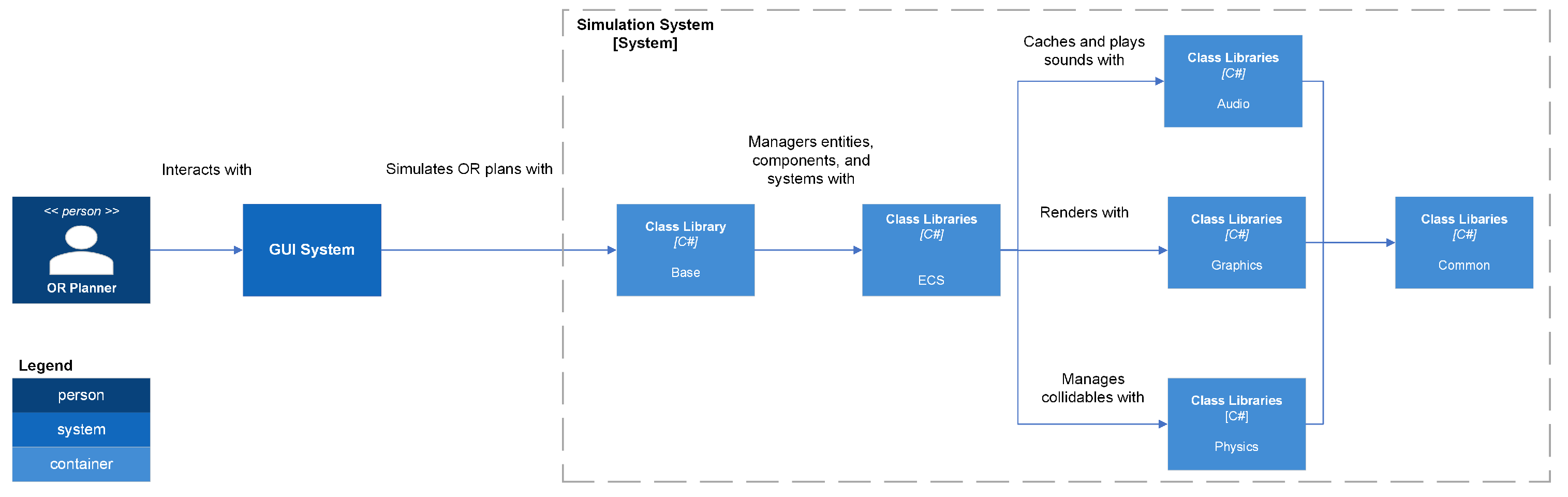
Figure 13 represents the container diagram for the simulation system. This container allows for the visualization of generated OR plans. An entity-component system (ECS) architecture is used to manage common components as well as the audio, graphics, and physics components.
Common
The Common namespace contains code that is used in one or more of the other BeVelS namespaces. It has the following namespaces: Comparers, Matrices, Meshes, OrthonormalBasisBuilders, Parallelism, Stopwatches, Threading, Threading.Windows, Triangles, Utilities, and Vectors.
Comparers has classes that enable comparing pairs of instances.
Vectors and matrices are used throughout BeVelS. Relevant supporting code can be found in the Matrices and Vectors namespaces. The Matrices namespace has an extension method that can be used to find the inverse of a Matrix4x4. In the Vectors namespace, there is an extension method that converts a Vector2 to a BepuUtilities.Int2. The Vectors namespace also has factories that create Vector2, Vector3, and Vector4 instances.
The Triangles namespace uses the struct TriangleContent to define a triangle in terms of three Vector3 instances. The Meshes namespace has a class named MeshContent that defines a mesh in terms of an array of TriangleContent instances.
The OrthonormalBasisBuilders namespace is related to the building of orthonormal bases. In particular, Duff2017OrthonormalBasisBuilder implements the approach developed by Duff et al. [
57].
The Parallelism namespace has a ParallelLooper class that implements a parallel for loop.
The Stopwatches namespace involves high precision profiling. Stopwatch is an implementation of a stopwatch that is similar to System.Diagnostics.Stopwatch. It obtains timestamp and frequency values by using P/Invoke to call the QueryPerformanceCounter and QueryPerformanceFrequency, respectively, functions in profileapi.h. In addition, there is a related StopWatchState class that keeps track of the state of a stopwatch.
The Threading and Threading.Windows namespaces contain code related to managing threads and tasks. The Threading namespace has a heuristic that uses Environment.ProcessorCount to estimate a thread count. Threading also has utility classes and factories related to Task Parallel Library tasks and the thread dispatcher in BepuUtilities. For example, CancellableTask is a wrapper that has two properties (a Task and a CancellationTokenSource) and a method for cancelling the task. The Threading.Windows namespace has an extension method that allows a task to be invoked asynchronously using a System.Windows.Threading.Dispatcher instance.
The Utilities namespace contains several helper classes. DisposeUtilities has code related to the IDisposable interface. IndexUtilities has methods that generate box and quad indices. QuaternionUtilities can pack a Quaternion into a Vector3 or ulong. SpanUtilities can convert a buffer into a span.
Audio
The Audio namespace uses NAudio, which is a C# audio library, and code based on the NAudio.Extras package to provide audio functionality to BeVelS. Audio has the following namespaces: Caching, Channels, Devices.Windows, Mixers, PlaybackEngines, Players, Readers, and Resamplers.
The Channels, Mixers, and Resamplers namespaces have factories that create ISampleProvider instances, including MonoToStereoSampleProvider, MixingSampleProvider, and WdlResamplingSampleProvider. The Players namespace has a factory for creating WaveOutEvent instances.
The Devices.Windows namespace has a class that uses WaveInterop in NAudio to get the number of available wave out devices.
The Readers namespace uses AutoDisposeAudioFileReader to read audio files. After reading an audio file, classes in the Caching namespace are used to store audio data as arrays of floats. The PlaybackEngine namespace uses AudioPlaybackEngine16 to manage the playback of cached audio files.
Graphics
Veldrid is a C# graphics library that is available under the MIT license. Veldrid is a common frontend for several different backends, including DirectX, Metal, OpenGL, OpenGLES and Vulkan. In BeVelS, Veldrid is used to provide graphics functionality. Code related to this is under the Graphics namespace. Some namespaces under Graphics only have wrapper classes, extension methods, and/or factories for Veldrid objects: BlendStates, CommandLists, Debugging, DepthStencilStates, Framebuffers, GraphicsDevices, GraphicsPipelines, RasterizerStates, ResourceLayouts, ResourceSets, Samplers, ShaderSets, Shaders, Swapchains, VertexLayouts, and Viewports.
In addition, the following namespaces are under Graphics: BackgroundRenderers, BufferConstants, Buffers, Cameras, Fonts, Glyphs, HTML, Images, KTX, LineRenderers, Meshes, PostProcessors, Recorders, ShapeRenderers, Shapes, Text, Textures, UILines, UIRenderers, and Utilities.
Code related to managing images falls under the Images namespace. There are classes for loading an image from a file into a renderable format, storing a collection of renderable images, and batching images.
The Meshes namespace has code for working with meshes. The MeshBuilder class uses dependencies, including AssimpNet, to load a mesh from a file. The MeshCache class is used for caching meshes during rendering.
Text-related code falls under the Fonts and Text namespaces. The Fonts namespace has structs that define character data, character pairs, and glyph sources. In addition, there are classes for batching glyphs, building a font, packing a font, storing the content of a font, and loading a font as a Veldrid Texture. The Text namespace has a class that uses the builder pattern for text.
In a shader, data can be uploaded to a graphics card using several different objects, including buffers, samplers, or textures. The Buffers, BufferConstants, Glyphs, HTML, Images, Shapes, and UILines namespaces and BeVelS.Physics.Constraints have code related to buffers and the data that can be uploaded to them. The Buffers namespace has four types of buffers: Constants, Index, Instances, and ShapeInstances. The BufferConstants namespace has structs that are used to upload data to constants buffers in vertex and fragment shaders. The data for index buffers are generated using relevant methods.
The Glyphs, HTML, Images, BeVelS.Physics.Constraints, and UILines namespaces have structs for uploading data to instances buffers. The Shapes namespace has structs associated with uploading data to shape instances buffers.
The Samplers namespace provides factories that can generate sampler instances. Code related to textures is under the KTX and Textures namespaces. The KTX namespace has code for loading a Khronos Texture as a Veldrid Texture. The Textures namespace has a TextureContent class that is used when loading other texture content, such as a font or an image, as a Veldrid Texture.
Renderers are divided into four categories: background, shapes and lines, screenspace, and post processors. A background renderer draws an image behind all other rendered items. Shapes and lines renderers draw shapes, such as boxes and cylinders, and lines, which are associated with constraints. Screenspace renderers draw UI elements, such as glyphs and images. The CompressToSwap post processor combines the outputs of the background, shapes and lines, and screenspace renderers and draws the combined image on the main swapchain.
The Cameras namespace contains code related to viewing renderings. It contains a class that defines a three-dimensional camera.
The Recorders namespace contains code associated with recording and saving renderings. The FrameRecorder class grabs the underlying texture of a rendering and copies it to a staging texture. The content of the staging texture is then copied to an image. The AnimatedGifRecorder class collects saved frames and uses them to form an animated image.
The Utilities namespace has a utility class for working with colours. It has PackColor methods that can pack a Vector3 or Vector4 colour into an uint. It has similar UnpackColor methods that can unpack an uint colour into a Vector3 or Vector4.
Physics
BepuPhysics2 is an open source C# physics library for rigid-body dynamics. BepuPhysics2 has several constrainable collidables, whose collisions can be detected.
Collidables are defined in the BepuPhysics.Collidables namespace. CollidableDescription and CollidableReference are used to describe and reference, respectively, collidables. A collidable generally implements either the IConvexShape or ICompoundShape interface, both of which implement the IShape interface. Most of the collidables, including Box, Capsule, ConvexHull, Cylinder, Sphere, and Triangle, are convex shapes that implement the IConvexShape interface. Mesh is a homogeneous compound of triangles. Heterogeneous compounds can be defined using BigCompound and Compound and associated helper classes.
The BepuPhysics.Constraints namespace contains code related to more than a dozen constraints. In addition, some classes related to constraints, including ConstraintBatch, ConstraintLocation, ConstraintReference, and ConstraintSet, are in the BepuPhysics namespace.
BepuPhysics2 is used to provide physics functionality to BeVelS. Code relevant to this falls under BeVelS.Physics. The base BeVelS.Physics namespace has factories for generating instances of various classes that fall under the base BepuPhysics namespace. In addition, BeVelS.Physics has the following namespaces: Callbacks, Collidables, Constraints, Meshes, and TimeSteps.
The Callbacks namespace has two callback structs. One struct is related to the narrow phase of collision detection. This struct has properties related to the contact springiness, maximum recovery velocity, and friction coefficient. It also has methods related to configuring contact manifolds and determining whether contact generation is allowed. The other is related to the pose integrator. It contains code related to gravity, linear and angular damping, and linear and angular velocities.
The Collidables namespace contains code related to collidables. There are factories that can generate Box, Capsule, ConvexHull, Cylinder, Mesh, Sphere, and Triangle instances. There also are factories for creating CollidableDescription and CollidableReference instances. In addition, there is an extension method that can add a collidable to a BepuPhysics2 simulation.
The Constraints namespace has classes and structs for extracting constraint lines and factories for creating instances of specific constraints
The Meshes namespace has utility classes and factories related to meshes. MeshHelper is used to load a mesh. The factories can generate different meshes, including deformed planes and fans.
The TimeSteps namespace has classes, which support fixed and variable timesteps, that can be used in conjunction with the Timestep method in a BepuPhysics2 simulation.
Entity Component System Architecture
DefaultEcs is used to allow BeVelS to have an Entity Component System (ECS) architecture. In this architecture, there are five primary types of objects:
Entity: An object that has a unique identifier.
Component: A wrapper struct that only contains data.
System: A class that implements the ISystem<T> interface and has business logic that acts on entities.
World: Each entity belongs to a world.
Message: A struct that can transfer data in a world using a publish/subscribe pattern.
In
Table 7, a ✓ is used to indicate the existence of a component, message, or system in BeVelS.