Abstract
A finite element dynamic modeling method considering the bolt non-uniform connection effect for the vibration characteristics of the disk–drum–shaft coupled structure is proposed. This structure consists of disks, drums, and hollow shafts, with significant differences in their geometric structures, which poses a challenge to modeling efficiency. A universal element with four nodes and 60 degrees of freedom is created in this paper. Based solely on the universal element and first-order shear theory, a universal expression for the stiffness matrix and mass matrix applicable to disk, drum, and shaft structures is derived to improve modeling efficiency. A dynamic model of the coupled structure is established by simulating the non-uniform connection effect of bolts and boundary conditions through the construction of an eight-degree-of-freedom spring-damping element. The effectiveness of the modeling method is verified through experiments, and the results showed good consistency between the natural frequency and vibration response of the simulation and those of the experiment. Finally, the influence of changes in bolt pre-tightening torque on the vibration characteristics of coupled structures is studied.
Keywords:
dynamic modeling; disk–drum–shaft coupled structure; finite element method; bolted connection effect; vibration characteristics MSC:
37N30
1. Introduction
Disk, drum, and shaft structures are widely used in rotating machinery such as aero-engines and gas turbines, and they usually operate in a coupled connection manner [1,2]. The disk–drum–shaft coupled structure faces extreme working conditions such as high speed, high temperature, high pressure, and heavy load during operation, and its vibration problem is particularly prominent [3,4,5,6]. With the continuous improvement of requirements for equipment in terms of performance, lightweight, and reliability, dynamic modeling and vibration characteristic analysis of the disk–drum–shaft coupled structure have important engineering significance. However, the disk–drum–shaft coupled structure includes three types of structures: disk, drum, and shaft, and the structural differences between the components are significant. In addition, there are many connection interfaces and complex coupling effects [7]. These factors bring great challenges to the efficient modeling and dynamic analysis of the disk–drum–shaft coupled structure.
In previous studies, some scholars have conducted dynamic modeling work on disk, drum, and hollow shaft structures, and some dynamic models based on the finite element method [8,9,10,11] and semi-analytical method [12,13,14,15] have been obtained. However, in practical engineering structures, the three types of structures are often interconnected and operate together through bolts [16,17,18]. Therefore, research has been conducted on coupling connection structures for disks, drums, and hollow shafts. Many studies on dynamic modeling of the relatively common disk–shaft coupling structure have been carried out, and some modeling methods based on the finite element method [19,20,21,22,23,24] and the semi-analytical method [23,24,25,26,27,28,29,30,31,32] have been proposed. At the same time, the semi-analytical dynamic modeling method for the disk–drum coupling structure has also been obtained [33,34,35,36,37,38,39].
At present, research on the dynamic modeling of disk–drum–shaft coupled structures has also received attention. For example, Li et al. [40] established a dynamic model of the drum shaft rotor system based on Sanders shell theory, considering the effects of centrifugal force and Coriolis force, as well as the initial circumferential tension caused by rotational speed. Artificial springs were used in the model to simulate elastic support conditions and coupling conditions. Zhao et al. [41] derived the energy functions of the shaft, disk, and drum based on the Euler–Bernoulli beam theory, Kirchhoff plate theory, and Sanders shell theory, and derived the motion equation of the flexible shaft–disk–drum rotor system through the Lagrange equation. Sun et al. [42] modeled a complex dual rotor using the Finite Entity Element Method (FSEM) and efficient model reduction techniques. Sun et al. [43] established a mechanical model for bolted connections by characterizing the mechanical relationships between adjacent nodes at the connection interface. A dynamic model of the drum–disk–shaft rotor assembly was established based on the connection interface mechanics model and finite element method. Yang et al. [44] established a finite element model of a flexible shaft–disk–drum rotor system considering rotational effects based on a beam shell spring hybrid element. Prabith et al. [45] constructed a dynamic model of a dual rotor system using conical Timoshenko beam elements, rigid disks, and rolling contact bearings. The appropriate model reduction technique based on component modal synthesis combined with Craig Bonton substructure technology is used to reduce the size of finite element models.
Studies on the aforementioned literature have revealed that there are still some deficiencies in the existing research regarding the dynamic modeling of the disk–drum–shaft coupled structure. In existing research, the semi-analytical method and the finite element method are the main dynamic modeling methods used for the single structures of disks, drums, and shafts, or their coupled connection structures. Semi-analytical models often simplify three types of structures, namely disks, drums, and shafts, into plates, shells, and beams. Therefore, this type of model has high modeling and computational efficiency. However, they involve a lot of modeling theories. Moreover, modeling for complex structures is difficult, and the solution accuracy is insufficient. For complex structures, finite element method has certain advantages in modeling accuracy. However, for structural dynamics modeling considering bolt connection effects, the modeling and solving process using commercial software is cumbersome, and the number of model unit divisions is relatively large. At the same time, for structures with significantly different structural characteristics, such as disks, drums, and shafts, the currently independently developed finite element modeling method lacks universality and requires different theoretical derivations. A unified modeling framework covering the three types of structures (disks, drums, and shafts) has not been formed. This makes the model of the disk–drum–shaft coupled structure relatively complex. In response to the above issues, this article proposes a finite element modeling method for the disk–drum–shaft coupled structure. The contributions and innovations of this research are as follows: (1) In view of the significant differences in the geometric structures of the three types of components, namely disks, drums, and shafts, an innovative four-node, 60-degree-of-freedom universal element was designed. Each node contains 15 degrees of freedom, which can adapt to the structural characteristics of disks, drums, and shafts. Meanwhile, based on the first-order shear theory, the general expressions of the unified stiffness matrix and mass matrix applicable to the three types of structures were derived. This universal element and the unified matrix do not require adjustment of the theoretical framework for different components. The modeling of the three types of structures can be realized by adjusting the local coordinate system and geometric parameters of the element. (2) An eight-degree-freedom spring-damper element was constructed. The mechanical properties of bolted connections are fully characterized through the series-parallel combination of six linear springs, two torsion springs, and two dampers. At the same time, based on the assumption of linear stiffness distribution in the bolt influence zone, the dynamic simulation of the non-uniform bolt connection effect is realized, and the quantitative functional relationship between the stiffness, damping in the spring-damper element and the bolt pre-tightening torque is given.
The organization of the paper is as follows. In Section 2, the research object and dynamic modeling method are introduced. The modeling method is experimentally validated in Section 3. In Section 4, the influence of the pre-tightening force of bolts at different positions on the dynamic characteristics of the structure is analyzed. Finally, some important conclusions are listed in Section 5.
2. Dynamic Modeling of the Disk–Drum–Shaft Coupled Structure
2.1. Research Object
A simplified disk–drum–shaft coupled structure (as shown in Figure 1) is taken as the research object in this paper. This structure is obtained by simplifying the high-pressure rotor structure of an aircraft engine. It includes three typical structures: disks, drums, and hollow shafts. The structure is symmetrical on both sides, including a left shaft, a right shaft, a left disk, a middle disk, a right disk, a left drum, and a right drum. The disk and drum are connected by drum flanges and bolts, while the shaft and disk are fixedly connected.
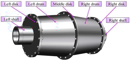
Figure 1.
Disk–drum–shaft coupled structure.
To facilitate the modeling of the disk–drum–shaft structure, the flange structure of the drum in Figure 1 is simplified, and the simplified model structure is shown in Figure 2. , and are, respectively, the center surface radius of the shaft, the small diameter center surface radius of the drum, and the large diameter center surface radius of the drum, , are the total length of the shaft and drum, respectively, , , , are the thickness of the shaft, left or right disk, drum, and middle disk, respectively.
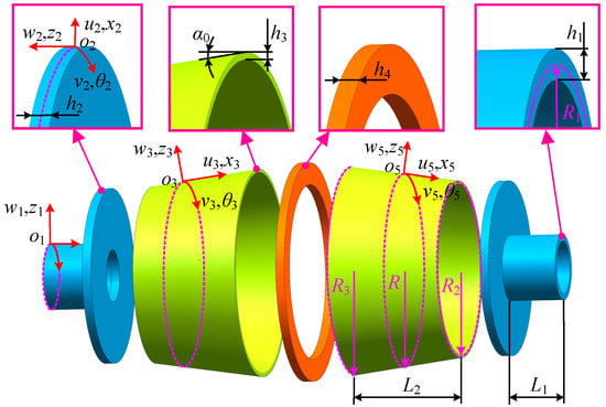
Figure 2.
The structure of disk, drum, and shaft.
The radius at different positions of the right drum structure satisfies the following relationship.
where is the top angle of the drum.
Orthogonal curvilinear coordinate systems are established for the disk, drum, and shaft, respectively. The local displacement of the left shaft, left disk, left drum, middle disk, right drum, right disk, and right shaft at any point on the center plane can be represented as in the cylindrical coordinate system. Among them, , and are consistent in all directions, and are consistent in all directions.
From Figure 2, it can be seen that there are significant differences in the structure of the disk, drum, and shaft. The radial dimension of the disk varies greatly, while the axial dimension is relatively small. The drum is a thin shell structure with significant dimensional variations in the axial direction and a slight taper. The axial dimension of the shaft is relatively large, while the radial dimension is relatively small. In order to improve modeling efficiency, a universal unit is created as shown in Figure 3, which includes 4 nodes (, , , ), each node containing 15 degrees of freedom. Therefore, the unit has a total of 60 degrees of freedom, defined as , , , , , , , , , , , , , , .
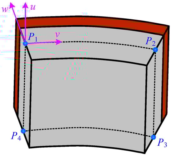
Figure 3.
Universal element for disk, drum, and shaft structures.
To establish a finite element dynamic model of the structure, first, the mass matrix and stiffness matrix of each structure, including the disk, drum, and shaft, need to be derived. Then, the problem of the bolt connection effect between the disk and drum needs to be solved. Finally, the dynamic equation is established. Below is a detailed introduction to the modeling process.
2.2. Mass Matrix and Stiffness Matrix of Disk, Drum, and Shaft
Based on the first-order shear theory and the plane stress assumptions, the general expressions of mass and stiffness matrices for disk, drum, and shaft structures with significant structural differences are derived in this section.
The displacement fields of the disk, drum, and shaft (, , and ) are defined as follows.
where , and are the components of displacement in the , and directions of the mid-plane, respectively, and are the rotational displacements of the mid-plane in the and directions, respectively.
According to the first-order shear theory, the expression for the strain vector at any position of the disk, drum, and shaft is as follows:
where is the strain vector, and are the axial strain and tangential strain at the distance from the mid-planes of disk, drum, and shaft, , and are the shear strains at the distances from the disk, drum, and shaft, and are the axial and tangential strains on the mid-plane, , and are the shear strains on the mid-plane, , and are the bending strains in the axial, tangential, and normal directions, respectively. Their specific expressions are as follows.
where is the angle between the local coordinate system and the global coordinate system of structures of the disk, drum, and shaft. For the disk, right drum, left drum, and shaft, the values of are , , and , respectively.
According to the generalized Hooke’s law, the stress–strain relationship of the disk, drum, and shaft can be expressed as follows:
where , are axial stress and tangential stress, , and are shear stresses, and can be expressed as follows [46]:
where and are elastic modulus and Poisson’s ratios of the disk, drum, and shaft, respectively.
The forces and moments acting on the disk, drum, and shaft can be expressed as follows:
where , and are the axial force, tangential force, and shear force, respectively, , and are the moments experienced by the disk, drum, and shaft in the axial, tangential, and normal directions, respectively, and are the shear forces.
Substituting Equation (7) into Equation (8) can obtain the following:
where
where is the shear correction coefficient, with a value of 5/6 [47,48,49,50], , and are, respectively, the tensile stiffness, coupling stiffness, and bending stiffness, with specific expressions as follows:
According to the assumption of small strain, assuming that the normal of the mid-plane of the deformed disk, drum, and shaft is perpendicular to the mid-plane, the displacement of any point on the middle plane of the element (the expression forms of , , and are the same as that of ) can be defined as follows:
where , , …, are polynomial coefficients.
The displacement vector of any node on the surface of a unit can be expressed as follows:
The relationship between the displacement field of any point in the disk, drum, and shaft and the node displacement can be expressed as follows:
where is the interpolation function matrix of the node, expressed as follows:
where , and are displacement interpolation functions of nodes. Furthermore, the element shape function matrices of the disk, drum, and shaft can be expressed as follows:
Furthermore, the strain displacement relationship within the elements of the disk, drum, and shaft can be obtained as follows.
where and are element strain matrixes.
Finally, the general expressions for the stiffness matrix and mass matrix of the disk, drum, and shaft are obtained, which can be expressed as follows [51]:
2.3. Coupling Connection Modeling of Disk–Drum–Shaft
The simulation methods of bolt-coupled connections and boundary condition connections are studied in this section. The bolt connection of this structure includes the connection between the left and right side disks and the left and right drums, as well as the connection between the middle disk and the left and right drums. The boundary connection conditions of this structure include the connection between the left shaft and the left boundary, and the connection between the right shaft and the right boundary.
2.3.1. Simulation of Bolted Connections and Boundary Conditions
Herein, multiple spring-damping groups are used to simulate the effect of bolt connection, and multiple spring groups are used to simulate the boundary connection effect. As shown in Figure 4, each spring-damping group is obtained by combining 6 linear springs, 2 torsion springs, and 2 dampers in series or parallel in three directions, and each spring group is obtained by combining 6 linear springs and 2 torsion springs in series or parallel in three directions.
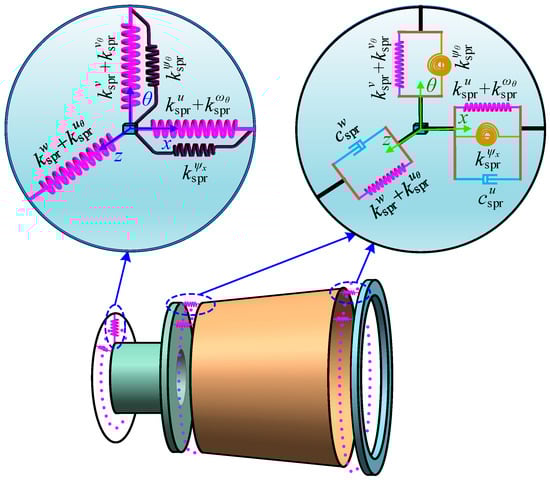
Figure 4.
Spring-damping group for simulating bolt connections and spring group for simulating boundary connections.
It should be noted that theoretically, each spring damping group is set with 8 directional stiffness springs and 8 directional damping. The stiffness and damping of each spring need to be obtained through identification. Since the bolt preload is mainly transmitted along the axial direction , axial contact slip is one of the main energy dissipation mechanisms. The structure has obvious flexible deformation in the radial direction , and the amplitude of the radial response is sensitive to changes in damping. The structure slip of circumferential direction is extremely small, and the response amplitude is not sensitive to damping changes in this direction. Therefore, the damping of axial direction and radial direction in this structure has a significant impact on the amplitude of the structural frequency response function. To further simplify the identification of spring damping group parameters, only the damping values of axial direction and radial direction are identified, and the remaining damping values are set to constants. Among them, , , and are the axial, circumferential, and radial spring stiffness, respectively, and are the torsional spring stiffnesses, and are the rotational spring stiffness of and around the -axis; is the rotational spring stiffness of along the -axis. and are damping in the axial and radial directions. The stiffness of the spring unit is defined as complex stiffness, which can be expressed as follows:
where “*” represents the complex stiffness spring corresponding to the spring stiffness, which includes the damping generated by the bolt joint.
In addition, it can be considered that when a bolt in a bolted joint is preloaded, it generates a circular pressure zone, and the size of this circular area is related to the nominal diameter of the bolt. This pressure zone is generally referred to as the bolt influence zone, as shown in Figure 5a,b. The mechanical effects in the bolted connection area are essentially non-uniform. To simulate the non-uniformity of each bolted connection area, it is assumed that the stiffness of a continuously distributed spring varies linearly in the radial direction within a circular region, and complex stiffness springs are used to simulate bolted connections within the bolt influence area. As shown in Figure 5c,d, represents the length of the bolt-affected zone of the bolt connection plate. Its length can be determined based on the structural parameters of the bolt joint, as shown as follows:
where is the maximum outer diameter of the contact between the gasket and the connected parts, is the sum of the thicknesses of the connected parts, is the half vertex angle in the triangle where and are located, and its value range is generally.
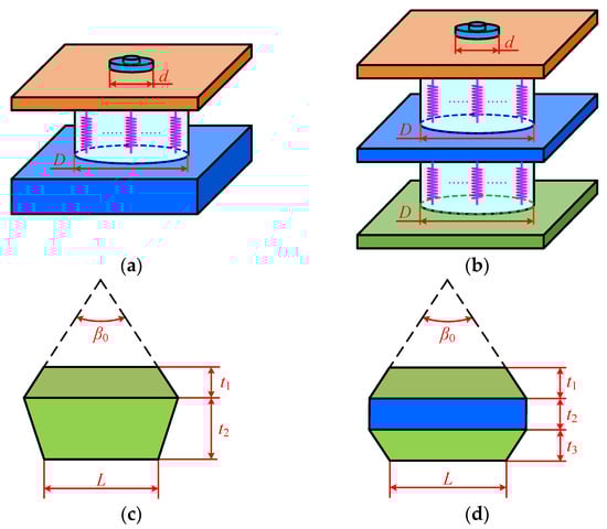
Figure 5.
Schematic diagram of bolt impact zone: (a) the diameter of the influence zone of bolt connection for double plate structure; (b) the diameter of the influence zone of bolt connection for three plate structure; (c) the length of the bolt connection influence zone of the double-plate structure; (d) the length of the bolt connection influence zone of the three-plate structure.
2.3.2. Continuous Expression of Spring Displacement for Bolted Connections and Boundary Conditions
Assuming that both bolt-coupled connections and boundary conditions must satisfy displacement continuity. The expressions for the displacement continuity conditions of the coupling connection between the left disk and the left drum, and between the middle disk and the left drum, are as follows:
According to Equations (32) and (33), similar expressions for the displacement continuity conditions of the coupling connection between the right disk and the right drum, and between the middle disk and the right drum, can also be obtained.
Derive the stiffness values of each spring based on the above coupling connections, and obtain the total coupling spring stiffness matrix as follows.
where , , , and are the stiffness matrixes of the composite spring connection between the left shaft and the left drum, the left drum and the middle plate, the right drum and the middle plate, and the right shaft and the right drum, and are the stiffness matrixes of the spring connection between the left shaft and the left boundary, and between the right shaft and the right boundary.
2.3.3. Establishment of Dynamic Equations
According to Equations (21) and (22), the stiffness matrix and mass matrix of the disk, drum, and shaft can be obtained. Next, the stiffness matrix and mass matrix of each structure are placed into the total stiffness matrix and total mass matrix according to their corresponding positions. Finally, the spring connection stiffness matrices corresponding to the coupling position and boundary connection position are placed into each coupling connection position and boundary connection position, and expressions of the total stiffness matrix and total mass matrix are as follows:
where and are the total stiffness matrix and total mass matrix of the disk–drum–shaft coupled structure, respectively. The specific grouping method of the stiffness matrix is shown in Figure 6.
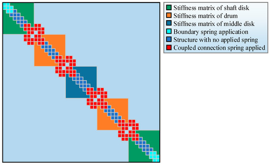
Figure 6.
Group set of stiffness matrix.
Next, the free vibration equation of the disk–drum–shaft coupled structure can be obtained as follows:
where is the eigenvector, is the nth order natural circular frequency.
Furthermore, the following natural frequencies of each order of the disk–drum–shaft coupled structure can be obtained as follows:
Applying a sinusoidal excitation force to the structure, its dynamic response equation can be expressed as follows:
where is the excitation force vector, is the total damping matrix, is the response amplitude vector, is the excitation frequency. Among them, the total damping matrix is formed by integrating and assembling the damping units of the bolted joints based on the structures of the disk, drum, and shaft.
The modal superposition method is used to solve the resonance response of the finite element model, and the dynamic equations of the disk–drum–shaft coupled structure under point excitation are decoupled through eigenvector . The decoupled dynamic equation is as follows:
where is the modal coordinate response of rth order, , , , and can be expressed as follows:
At the excitation frequency , the modal coordinate response of the rth order can be obtained by solving Equation (37).
Finally, the vibration response of the disk–drum–shaft coupled structure can be obtained as follows:
The vibration response in Equation (38) is a plurality, and the response amplitude can be obtained by performing modulo operation on .
3. Validation of the Effectiveness of the Dynamic Model
3.1. Comparative Verification with ANSYS Software Simulation
3.1.1. Modeling of the Disk–Drum–Shaft Coupled Structure in ANSYS Software
Finite element models of the disk, drum, shaft, and bolts are established using SOLID186 solid elements. Contact pairs, including bolt head–disk contact pairs, disk–drum flange contact pairs, and nut–drum flange contact pairs are created to simulate the connection effect of the bolted joint. The contact parameters of the bolted joint include dynamic friction coefficient, tangential stiffness coefficient, and normal stiffness coefficient, which are 0.3, 0.3, and 1.1, respectively. A preload of 3125 N (equivalent to a preload torque of 5 N·m) is applied to the bolt shank in each bolted joint. Fixed constraints are applied to both ends of the shaft as boundary conditions. Through the above steps, the finite element model of the entire disk–drum–shaft coupled structure is established as shown in Figure 7. This finite element model has a total of 93,474 elements and 375,197 nodes.
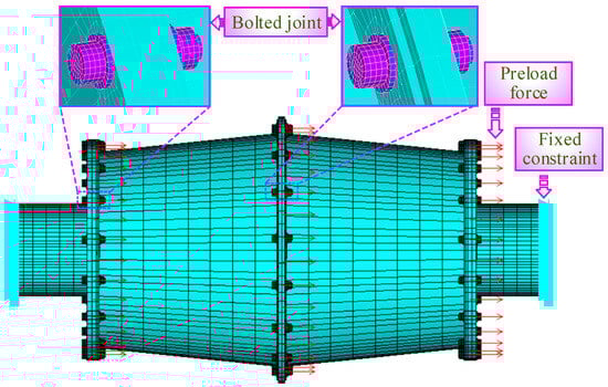
Figure 7.
Finite element modeling of disk–drum–shaft coupled structure by ANSYS software.
3.1.2. Comparison of Computational Efficiency
The solution time of the model proposed in this paper is compared with that of the ANSYS model. The computer hardware configuration used is as follows: the CPU is an i7 14700KF, the memory is 64 GB DDR5, the MATLAB version is 2021b, and the ANSYS version is Mechanical APDL 19.2. Both models are solved and calculated using the same computer, and the first 6 orders of natural frequencies, modal shapes, and the first-order vibration response are solved, respectively. The solution time of the model proposed in this paper is 159 s, and that of the ANSYS model is 1913 s. That is to say, the solution time of the proposed model is 8.31% of that of the ANSYS model.
3.1.3. Comparison of Calculation Accuracy
The first six orders of natural frequencies calculated by the two models are selected for comparison, and the comparison results are shown in Figure 8. The maximum deviation of the natural frequencies between the two models is 3.36%, the minimum deviation is 0.42%, and the average deviation is 1.99%. It can be seen from the comparison results that the natural frequencies solved by the model proposed in this paper are in good agreement with those solved by the ANSYS model.
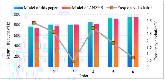
Figure 8.
Comparison of natural frequencies between the model proposed in this paper and the ANSYS model.
3.2. Comparison and Verification with Test Results
3.2.1. Problem Description
The experimental testing system for the disk–drum–shaft coupling structure is shown in Figure 9. The main hardware equipment required for the experimental testing system is shown in Table 1. The material parameters of the disk, drum, and shaft are shown in Table 2. The two ends of the coupling structure are fixed on the fixture with 8 M10 bolts, with the pre-tightening force of each bolt set to . The pre-tightening force of the bolts inside the disk–drum–shaft coupled structure is . The modal testing and response testing will be conducted through this testing system. The impact method is used for modal testing. A point excitation exciter is used to provide excitation force for response testing. In order to effectively ensure the collection effect of the response, two acceleration sensors are arranged at different positions on the test piece.
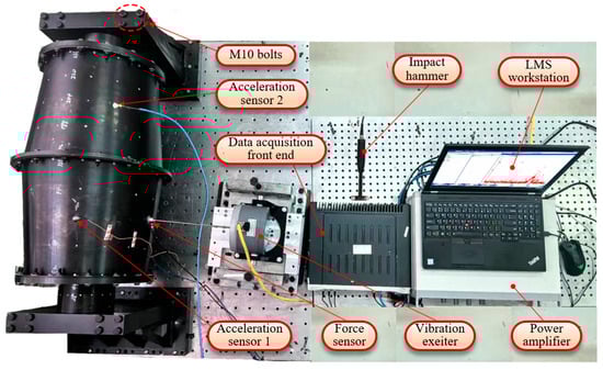
Figure 9.
Testing system for the disk–drum–shaft coupling structure.

Table 1.
Equipment of testing systems for disk–drum–shaft coupled structure.
Table 2.
Structural parameters and material parameters of disk, drum, and shaft.
- (1)
- Impact modal test
The excitation source for the hammer impact test comes from a modal hammer. A pulse excitation signal is applied to the disk–drum–shaft coupled structure by striking it with the modal hammer. Then, the acceleration sensors attached to the disk–drum–shaft coupled structure will pick up the acceleration signals of the vibration of the disk–drum–shaft coupled structure, which are received and processed by the LMS data acquisition device. Finally, the LMS data acquisition device transmits the processed signals to the notebook workstation for real-time display, so as to obtain the acceleration response signals of the vibration of the disk–drum–shaft coupled structure and form the final closed-loop system.
- (2)
- Fixed-frequency experimental test of the flexible rod exciter
The excitation source for the fixed-frequency experimental test of the flexible rod exciter comes from the flexible rod exciter. First, the mobile workstation sets a certain excitation frequency and excitation force, and transmits them to the LMS data acquisition device for data processing. The LMS data acquisition device then transmits the processed signal to the power amplifier to amplify the signal. The amplified signal is then transmitted to the flexible rod exciter to excite the disk–drum–shaft coupling structure. After that, the force sensor located at the front end of the flexible rod exciter and the acceleration sensors attached to the disk–drum–shaft coupling structure, respectively, transmit the force signal and acceleration signal generated during excitation to the LMS data acquisition device for processing. Finally, the LMS data acquisition device transmits the processed signal to the mobile workstation, thereby obtaining the point excitation response signal of the disk–drum–shaft coupling structure and forming the final closed-loop system.
3.2.2. Identification of Bolt Joint Parameters
In the disk–drum–shaft structure, different bolt pre-tightening forces will result in different stiffness and damping at the bolt joint. The pre-tightening force of bolts is simulated by changing the spring parameters (stiffness and damping values) in the bolt influence zone in this study. In order to simulate the connection effect of bolts in test specimens more accurately, the method of reverse identification is used to determine the stiffness and damping values at the bolt connection position. Herein, parameter identification is carried out based on two bolted connection unit structures, as shown in Figure 10. Each unit structure only contains one set of bolts and nuts. The bolt connection of the two side disks in the disk–drum–shaft structure is simulated by unit structure 1, which represents the connection of the two-layer plates. The bolted connection of the middle disk in the disk–drum–shaft structure is simulated using unit structure 2, which represents the connection of three-layer plates. The hammer impact testing and the response testing are conducted on two unit structures separately, and the test data is used to identify the stiffness and damping of the bolts.
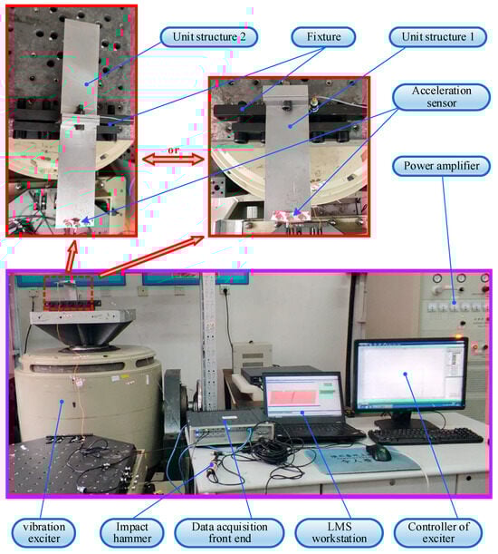
Figure 10.
Test experimental system for stiffness and damping reverse identification of bolted connection unit structure.
Based on the natural frequencies of one to five orders and the frequency response functions amplitude of the one to two orders of the bolted connection unit structures, the relationships between the stiffness, damping, and bolt pre-tightening torque of the bolted connection in unit structure one are obtained. The specific functional relationships are shown in Equations (43)–(52).
Similarly, the functional relationships between the stiffness, damping, and pre-tightening torque of the bolted connections in unit structure two are shown in Equations (53)–(62).
After obtaining the above nonlinear fitting polynomial expressions for stiffness and damping, it is necessary to evaluate the fitting effect. Calculate the goodness of fit for the fitting curves of the stiffness and damping of each bolted connection in accordance with Appendix A. The average values of the goodness of fit for the stiffness and damping curves of the bolted connections in unit structure one are 0.994 and 0.999, respectively. The average values of the goodness of fit for the stiffness and damping curves of the bolted connections in unit structure two are 0.999 and 0.999, respectively. This indicates that the fitting effect of the nonlinear fitting polynomials for stiffness and damping is good.
3.2.3. Natural Characteristic Verification
The stiffness functions obtained in Section 3.2.2 are substituted into the dynamic model of the disk–drum–shaft structure, the stiffness values of the springs coupled at the left axis and left drum in the model, as well as the stiffness values of the springs coupled at the middle disk of the left drum, can be determined. The two ends of the disk–drum–shaft structure in the test system are fixed, and the spring stiffness at both the left and right boundary conditions is set to . In this way, the parameters of the connection positions in the model are determined. Furthermore, modal analysis is conducted using the dynamic model of the disk–drum–shaft structure, and modal data (natural frequency and modal shapes) are extracted and compared with test results. The comparison results of natural frequencies are shown in Figure 11, and the absolute values of natural frequency deviations of the one to six orders are calculated. Among them, the maximum deviation is 2.87%, the minimum deviation is 0.71%, and the average deviation is 1.58%. The comparison results of modal shapes are shown in Table 3. Furthermore, the Modal Assurance Criterion (MAC) of the mode shapes is calculated, and the calculation results are shown in Figure 12. The average value of the first 6 orders of MAC is 0.895. Through comparison, it is found that the simulated modal shapes match well with the tested modal shapes. These comparative results of natural frequency and mode shape validate the effectiveness of the modeling method.
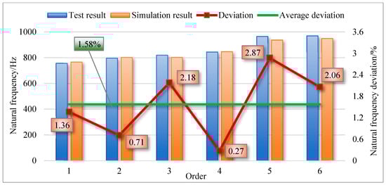
Figure 11.
Comparison of natural frequencies between test results and simulation results.
Table 3.
Comparison of modal shapes between test results and simulation results.
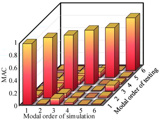
Figure 12.
MAC of testing results and simulation results.
3.2.4. Vibration Response Verification
The comparative analysis of the first-order displacement response of the disk–drum–shaft coupled structure is performed. The testing system shown in Figure 9 is used to conduct the sweep frequency response testing. The excitation force is set to 1N. According to the test results of natural frequency in Section 3.2.3, the excitation frequency range is set to 740 Hz~770 Hz for response testing. The acceleration response data of two test points are extracted and analyzed to obtain the resonance frequency of the structure as 751.25 Hz. Furthermore, convert the tested acceleration response into a displacement response using the following equation.
where is the displacement response, is the frequency value of each measuring point, and is the acceleration response.
The displacement response curve of the test is compared with that of the simulation, as shown in Figure 13. From the comparison results, it can be seen that the deviation of the resonance frequency is 2.07%. The experimental and simulated displacement response deviations of measuring point 1 and measuring point two are 4.07% and 5.42%, respectively. Through the above comparison, it can be seen that the response of simulation and experiment has good consistency, which also verifies the effectiveness of the modeling method.
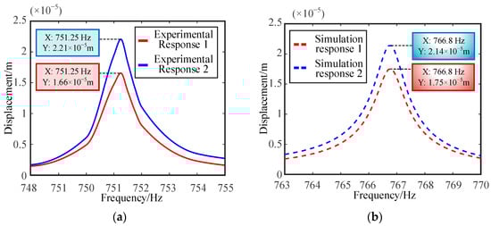
Figure 13.
Vibration response curves of experiment and simulation: (a) test result; (b) simulation result.
4. The Influence of Bolt Pre-Tightening Torque on the Dynamic Characteristics of Coupled Structure
Based on the dynamic model of the disk–drum–shaft coupled structure considering the bolt connection effect proposed in this paper, the influence of bolt pre-tightening torque at different positions on the dynamic characteristics of the disk–drum–shaft coupled structure will be studied in this section. Three bolt groups are defined from left to right based on their positions, and they were named Group 1, Group 2, and Group 3, respectively, as shown in Figure 14. Here, three operating conditions are defined as follows: the pre-tightening torque of bolts in groups 1, 2, and 3 are synchronously changed; only the pre-tightening torque of bolts in groups 1 and 3 is synchronously changed; and only the pre-tightening torque of bolts in groups 2 is changed. The pre-tightening torque changes in the three bolt groups are shown in Table 4.
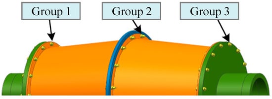
Figure 14.
Bolt group.
Table 4.
Three operating conditions for changing the pre-tightening torque of bolts.
4.1. Analysis of Dynamic Characteristics Under Operating Condition One
According to the variation in bolt pre-tightening torque in condition one, the connection stiffness and damping of the corresponding bolt group are introduced into the model, and the vibration response of the disk–drum–shaft coupled structure under each pre-tightening force is calculated separately. The resonance frequencies of one to six orders under different bolt pre-tightening torques are shown in Figure 15. From the graph, it can be seen that as the pre-tightening torque of the bolt increases, the resonance frequency of each order shows a slight increase trend. Among these orders, the fourth order resonance frequency exhibits a significant increase compared to the other orders. It is precisely for this reason that the overall change trend of resonance frequencies from first order to sixth order is consistent under different pre-tightening torques. Meanwhile, the displacement responses of two points in the structure are extracted, and the displacement response curves under different pre-tightening torques are shown in Figure 16. Furthermore, the displacement response amplitudes of two points under different pre-tightening torques are extracted for trend analysis. As shown in Figure 17, with the increase in pre-tightening torque, the displacement response amplitudes of both points show an increasing trend.
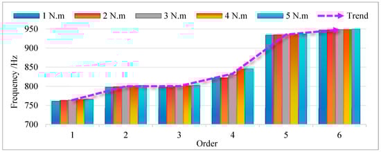
Figure 15.
Resonance frequencies of first to sixth orders under condition one.
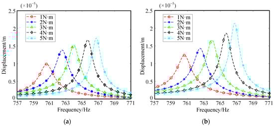
Figure 16.
Displacement response curves of two points under condition one: (a) Point 1; (b) Point 2.
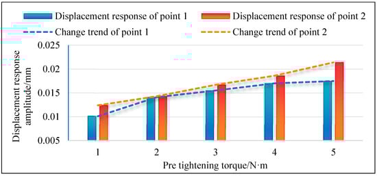
Figure 17.
The variation trend of displacement response for two points under condition one.
4.2. Analysis of Dynamic Characteristics Under Operating Condition Two
According to the variation in bolt pre-tightening torque in condition two, simulation calculations are carried out to obtain the vibration response of the disk–drum–shaft coupled structure under various pre-tightening forces. The resonance frequencies of one to six orders under different pre-tightening torques are shown in Figure 18. From the graph, it can be seen that as the pre-tightening torque of the bolt increases, the resonance frequency of each order shows a slight increasing trend. Moreover, the variation trend of resonance frequencies from first to sixth order is basically consistent. This also makes the trend of resonant frequency changes from first to sixth order completely consistent under different pre-tightening torques. Meanwhile, the displacement responses of two points in the structure are extracted, and the displacement response curves under different pre-tightening torques are shown in Figure 19. Furthermore, the displacement response amplitudes of two points under different pre-tightening torques are extracted for trend analysis. As shown in Figure 20, with the increase in pre-tightening torque, the displacement response amplitudes of both points generally show an increasing trend.
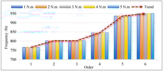
Figure 18.
Resonance frequencies of first to sixth orders under condition two.
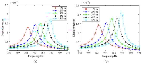
Figure 19.
Displacement response curves of two points under condition two: (a) Point 1; (b) Point 2.
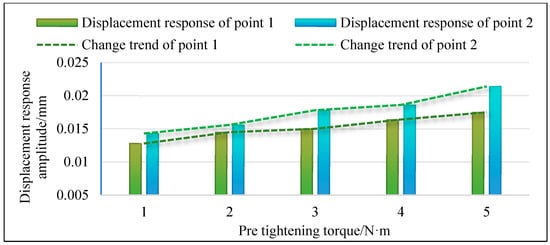
Figure 20.
The variation trend of displacement response for two points under condition two.
4.3. Analysis of Dynamic Characteristics Under Operating Condition Three
Similarly, based on the variation in bolt pre-tightening torque in condition three, simulation calculations are conducted to obtain the vibration response of the disk–drum–shaft coupled structure under various pre-tightening forces. The resonance frequencies of one to six orders under different pre-tightening torques are shown in Figure 21. It can be seen that as the pre-tightening torque of the bolt increases, the resonance frequency of each order shows a small increasing trend. Compared to other orders, the resonance frequency of the 4th order increases significantly. Therefore, the overall trend of changes from first to sixth order is consistent under different pre-tightening torques. Meanwhile, the displacement responses of two points in the structure are extracted, and the displacement response curves under different pre-tightening torques are shown in Figure 22. Furthermore, the displacement response amplitudes of two points under different pre-tightening torques are extracted for trend analysis. As shown in Figure 23, with the increase in pre-tightening torque, the displacement response amplitudes of both points show an increasing trend.
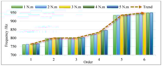
Figure 21.
Resonance frequencies of first to sixth orders under condition three.
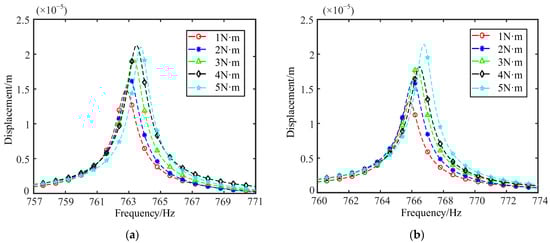
Figure 22.
Displacement response curves of two points under condition three: (a) Point 1; (b) Point 2.
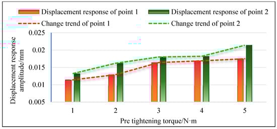
Figure 23.
The variation trend of displacement response for two points under condition three.
4.4. Discussion on the Mechanism of Vibration Amplitude Change
The substructures of the research object in this paper are assembled into a disk–drum–shaft coupled structure using bolt connections. As the core force-transmitting unit of this assembled structure, the stiffness of the entire disk–drum–shaft coupled structure depends on the contact surface compressive stress and the axial constraint capacity of the bolts themselves. Meanwhile, the damping of the entire coupled structure mainly comes from the energy dissipation due to micro-slip on the contact surfaces and the energy dissipation at the bolt-thread interface. When the bolt pre-tightening torque (i.e., pre-tightening force) increases, there are two interrelated mechanical changes with different degrees of influence.
(1) The stiffness of the overall structure has been moderately improved. It is true that an increase in preload will enhance the contact stiffness of the contact surface and the axial stiffness of the bolts, thereby improving the overall stiffness of the disk–drum–shaft coupled structure. However, it should be noted that the overall stiffness of the disk–drum–shaft coupled structure is mainly dominated by the inherent stiffness of its base components (the disk, drum, and shaft are all made of 45 steel), and the additional stiffness contributed by the bolted joints accounts for only a small proportion of the total stiffness. This is also confirmed by the modal analysis results in Section 4.1, Section 4.2 and Section 4.3. When the preload torque increases from 1 N·m to 5 N·m, the maximum increase in the 1st to 6th order resonance frequencies is only 2.87% (4th order mode), indicating that the effect of increasing the bolt preload on improving the overall stiffness is limited.
(2) The damping of the overall structure is significantly reduced. An increase in bolt preload leads to a rise in the contact surface pressure between the disk and the drum, as well as between the drum and the shaft flange, which greatly suppresses micro-slip between the contact surfaces. This directly weakens the primary energy dissipation pathway of bolted connections. Section 3.2 also confirms through inverse parameter identification of bolted connection units that as the preload torque increases, both axial and radial damping coefficients show a continuous downward trend.
To summarize, the reduction in the damping of bolted joints contributes far more to the increase in vibration amplitude than the inhibitory effect of its stiffness improvement, which has become the dominant factor causing the increase in vibration amplitude due to higher bolt preload. Therefore, for the design of bolted connections in rotating machinery such as aero-engines and gas turbines, it is necessary to balance the impact of preload on connection reliability and vibration characteristics, and avoid the risk of increased vibration caused by excessive pursuit of high preload.
5. Conclusions
This paper proposes a general finite element dynamic modeling method considering the non-uniform connection effect of bolts for the core disk–drum–shaft coupling structure in rotating machinery such as aero-engines. Through theoretical derivation, software comparison, and experimental verification, the influence of bolt pre-tightening torque on the dynamic characteristics of the structure is systematically analyzed. The main research conclusions are as follows:
(1) Aiming at the problems of low modeling efficiency and inconsistent theoretical frameworks caused by the significant geometric differences among the three types of substructures (disks, drums, and shafts), a highly versatile modeling framework is proposed. An innovative four-node, 60-degree-of-freedom universal element is designed. Based on the first-order shear theory and the plane stress assumption, the unified general expressions for the stiffness matrix and mass matrix applicable to the three types of substructures are derived. This framework eliminates the need to adjust the theoretical system for different substructures; modeling can be completed simply by modifying the local coordinate system and geometric parameters of the element, thus solving the cumbersome problem of traditional finite element methods, which require separate derivation of matrices for disks, drums, and shafts. It achieves accurate simulation of the non-uniform connection effect of bolts, quantifies the correlation between connection parameters and pre-tightening torque, and constructs an eight-degree-of-freedom spring-damper module. The dynamic simulation of the non-uniformity of bolted connections is realized through the assumption of “linear distribution of radial stiffness in the bolt influence zone”. The above modeling strategies significantly improve the modeling efficiency of the disk–drum–shaft coupled structure.
(2) Dual verification is conducted using the ANSYS solid element model and physical experiments. In terms of modal characteristics, the maximum deviation of the first to sixth order natural frequencies from the ANSYS results is only 3.36% (with an average of 1.99%), and the maximum deviation from the experimental results is 2.87% (with an average of 1.58%). The average Modal Assurance Criterion (MAC) with the experimental results reaches 0.895, indicating a high degree of modal shape matching. In terms of vibration response, the deviation between the experimental value and the simulated value of the first-order resonance frequency is 2.07%, and the deviations of the displacement response amplitudes at the two points are 4.07% and 5.42%, respectively, all verifying the accuracy of the model.
(3) Through the analysis of three sets of pre-tightening torque working conditions, it is found that when the bolt pre-tightening torque increases, the natural frequency of the structure increases slightly, but the amplitude of the vibration response increases significantly. The core mechanism of this phenomenon is that the increase in pre-tightening torque inhibits the micro-slip of the contact surface, resulting in a decrease in structural damping (mainly from energy consumption at the contact surface), and the promoting effect of reduced damping on amplitude is much greater than the inhibiting effect of increased stiffness. This provides a theoretical basis for “avoiding excessive pursuit of high pre-tightening torque leading to vibration risks” in engineering design.
(4) This study provides a feasible modeling method for the dynamic analysis of heavy rotating machinery such as aero-engine high-pressure rotors, gas turbines, and water turbines. Meanwhile, the correlation law of “pretightening torque-stiffness-damping-vibration response” presented in this paper can guide engineers to control the range of pretightening torque (taking into account the balance between stiffness and damping) and reduce the risk of resonance under the premise of ensuring connection reliability.
(5) Although this paper realizes efficient modeling and parameter analysis of the disk–drum–shaft coupling structure, there are still the following limitations. The model does not consider the effects of centrifugal force and thermal stress under high-temperature and high-speed working conditions. In addition, only fixed constraint boundaries have been analyzed. In actual rotating machinery, shaft ends are mostly supported by bearings. In the future, the bearing support characteristics need to be integrated into the overall model to further improve engineering applicability.
Author Contributions
K.X.: funding acquisition and writing—original draft. H.Z.: methodology and writing—original draft. B.W.: resources, supervision. D.D.: visualization, validation, and data curation. All authors have read and agreed to the published version of the manuscript.
Funding
This work was supported by the National Natural Science Foundation of China (52375085), Guangdong Basic and Applied Basic Research Foundation (2024A1515010675), Natural Science Foundation of Liaoning Province (2023-MSBA-031), National Natural Science Foundation of China (Grant No. 52405094), the Postdoctoral Fellowship Program of CPSF under Grant Number GZC20240223.
Data Availability Statement
The original contributions presented in this study are included in the article. Further inquiries can be directed to the corresponding author.
Conflicts of Interest
Author Hongsheng Zhang was employed by the company Jiangnan Shipyard (Group). The remaining authors declare that the research was conducted in the absence of any commercial or financial relationships that could be construed as a potential conflict of interest.
Appendix A
References
- Wang, R.H.; Wang, Q.S.; Guan, X.L.; Shao, W. The coupling free vibration characteristics of a rotating functionally graded shaft-disk system in thermal field. Thin-Walled Struct. 2022, 176, 109278. [Google Scholar] [CrossRef]
- Li, L.; Luo, Z.; He, F.X.; Sun, K.; Yan, X.L. An improved partial similitude method for dynamic characteristic of rotor systems based on Levenberg-Marquardt method. Mech. Syst. Sig. Process. 2022, 165, 108405. [Google Scholar] [CrossRef]
- Du, D.X.; Sun, W.; Yan, X.F.; Liu, H.H.; Xu, K.P.; Qin, Z.Y. Modelling and analysis of nonlinear vibrations for a coupling hard-coated ring disc-cylindric shell structure under piecewise-continuous coupling conditions. Int. J. Mech. Sci. 2022, 215, 106940. [Google Scholar] [CrossRef]
- Li, Y.Q.; Wen, C.M.; Luo, Z.; Jin, L. Bifurcation studies of a bolted-joint rotor system subjected to fixed-point rubbing fault. Nonlinear Dyn. 2022, 110, 3045–3073. [Google Scholar] [CrossRef]
- Stocki, R.; Szolc, T.; Tauzowski, P.; Knabel, J. Robust design optimization of the vibrating rotor-shaft system subjected to selected dynamic constraints. Mech. Syst. Sig. Process. 2012, 29, 34–44. [Google Scholar] [CrossRef]
- Wei, S.H.; Lu, W.X.; Chu, F.L. Speed characteristics of disk-shaft system with rotating part looseness. J. Sound Vib. 2020, 469, 115127. [Google Scholar] [CrossRef]
- Jin, M. The nonlinear dynamic characteristics of the aero-turboshaft engine rotor blade casing rubbing system with the curvic couplings considering the elastoplastic stage. Eng. Anal. Bound. Elem. 2024, 161, 78–102. [Google Scholar] [CrossRef]
- Li, T.; Wen, Z.H.; Zhao, B.B.; Sun, Q.C. A novel collaborative optimization assembly process method for multi-performance of aeroengine rotors. Int. J. Adv. Manuf. Technol. 2023, 125, 1827–1843. [Google Scholar] [CrossRef]
- Jin, Y.H.; Hou, L.; Chen, Y.S.; Lu, Z.Y. An effective crack position diagnosis method for the hollow shaft rotor system based on the convolutional neural network and deep metric learning. Chin. J. Aeronaut. 2022, 35, 242–254. [Google Scholar] [CrossRef]
- Yang, Y.F.; Wu, Q.Y.; Wang, Y.L.; Qin, W.Y.; Lu, K. Dynamic characteristics of cracked uncertain hollow-shaft. Mech. Syst. Sig. Process. 2019, 124, 36–48. [Google Scholar]
- Barbosa, P.C.P.F.; Del Claro, V.T.S.; Sousa, J.M.S.; Cavalini, A.A.; Steffen, V. Experimental analysis of the SHBT approach for the dynamic modeling of a composite hollow shaft. Compos. Struct. 2020, 236, 111892. [Google Scholar] [CrossRef]
- Kou, H.J.; Zhang, Y.W.; Lee, H.P.; Shi, Y.X.; Du, J.J.; Zhu, Z.D.; Zhang, F.; Zeng, L. Rubbing features of the bladed drum rotor under a novel coupled axial-radial thermal effect. Acta Mech. Sin. 2024, 40, 523034. [Google Scholar] [CrossRef]
- Yue, C.; Chen, J.T.; Zheng, X.M.; Wang, C.G.; Liu, H. Thin-layer element method for multi-stage rotor bolt loosening identification. J. Mech. Sci. Technol. 2024, 38, 6489–6505. [Google Scholar] [CrossRef]
- Xu, Q.; Hou, L.; Hou, L.X.; Li, Z.G.; Ren, S.X.; Aboudaif, M.K.; Awwad, E.M.; Saeed, N.A. Free vibration analysis of C/SiC blisk based on modified global mode method. Thin-Walled Struct. 2024, 204, 112285. [Google Scholar] [CrossRef]
- Yao, M.H.; Song, R.D.; Niu, Y.; Wu, Q.L.; Yang, Y.J.; Ma, L. Stepwise equivalent modeling for the blisk under nonlinear aerodynamic excitation considering fluid-structure interaction. Aerosp. Sci. Technol. 2025, 159, 110015. [Google Scholar] [CrossRef]
- Li, Y.Q.; Long, T.L.; Luo, Z.; Wen, C.M.; Zhu, Z.M.; Jin, L.; Li, B. Numerical and experimental investigations on dynamic behaviors of a bolted joint rotor system with pedestal looseness. J. Sound Vib. 2024, 571, 118036. [Google Scholar] [CrossRef]
- Li, L.; Luo, Z.; Wu, F.Y.; He, F.X.; Sun, K. Frequency spectrum analysis of the rotor system with bolted joint, Numerical and experimental verification. Appl. Math. Model. 2023, 118, 745–761. [Google Scholar] [CrossRef]
- Zhang, Y.; Sun, W.; Zhang, H.; Ma, H.W.; Du, D.X.; Xu, K.P. Design and implementation of the adaptive vibration control for bolted composite plates under variable loads. Mech. Syst. Sig. Process. 2025, 229, 112496. [Google Scholar] [CrossRef]
- Wang, N.; Jiang, D.; Xu, H. Effects of rub-impact on vibration response of a dual-rotor system, theoretical and experimental investigation. Exp. Tech. 2020, 44, 299–311. [Google Scholar] [CrossRef]
- Tuzzi, G.; Schwingshackl, C.W.; Green, J.S. Study of coupling between shaft bending and disc zero nodal diameter modes in a flexible shaft-disc assembly. J. Sound Vib. 2020, 479, 115362. [Google Scholar] [CrossRef]
- Sun, H.Y.; Yuan, H.Q. Reduced order models and coupling characteristics of the mistuned blade-disk-shaft integration rotor. J. Vib. Eng. Technol. 2021, 9, 2001–2018. [Google Scholar] [CrossRef]
- Fu, C.; Lu, K.; Yang, Y.F.; Xie, Z.L.; Ming, A.B. Nonlinear vibrations of an uncertain dual-rotor rolling bearings system with coupling misalignment. J. Nonlinear Math. Phys. 2022, 29, 388–402. [Google Scholar] [CrossRef]
- Shen, M.Y.; Wang, Q.S.; Wang, R.H. Investigation on the vibration mechanisms of a rotating FG-GPLRC shaft-disk-shell combined system. Structures 2023, 56, 105049. [Google Scholar] [CrossRef]
- Shao, J.; Wu, J.G.; Yang, K.; Zhang, Y. Dynamic characteristic analysis of a twin-spool rotor-casing system with looseness and intershaft rubbing coupling faults. J. Mech. Sci. Technol. 2024, 38, 101–120. [Google Scholar] [CrossRef]
- Li, Y.Q.; Luo, Z.; Wang, J.W.; Ma, H.; Yang, D.S. Numerical and experimental analysis of the effect of eccentric phase difference in a rotor-bearing system with bolted-disk joint. Nonlinear Dyn. 2021, 105, 2105–2132. [Google Scholar] [CrossRef]
- Jin, M.; Wang, A.L.; Wang, Q.S.; Wang, L.K.; Zhang, H.B. The vibration characteristics of central tie rod rotor-blade-bearing coupling system considering the influence of the Hirth couplings. Arch. Appl. Mech. 2022, 92, 3533–3561. [Google Scholar] [CrossRef]
- She, H.X.; Li, C.F. Analytical interpretation and numerical simulation on the dynamic coupling of a flexible cyclic blades-disk-shaft system. Appl. Math. Model. 2022, 112, 726–748. [Google Scholar] [CrossRef]
- Zhang, Y.M.; Tang, J.Q.; Xu, X.P. Modal analysis and multidisciplinary optimization of disk-shaped rotor in MSCMG. Int. J. Mech. Sci. 2022, 226, 107387. [Google Scholar] [CrossRef]
- Cui, Y.S.; Wang, Y.Q. Effect of disk flexibility on nonlinear vibration characteristics of shaft-disk rotors. Acta Mech. Sin. 2024, 40, 523140. [Google Scholar] [CrossRef]
- Cui, Y.S.; Wang, Y.Q. Free vibrations of axially loaded thin-walled shaft-disk rotors subjected to non-uniform temperature field. Thin-Walled Struct. 2024, 196, 111461. [Google Scholar] [CrossRef]
- Yang, Y.J.; Yao, M.H.; Niu, Y.; Wu, Q.L.; Wang, C. Model verification and vibration analysis of the four-disk hollow flexible shaft rotor system. Int. J. Mech. Sci. 2024, 268, 109051. [Google Scholar] [CrossRef]
- Nazari, M.M.; Rahi, A.; Khabbaz, R.S. Stability analysis of a hybrid composite rotor with the three-node finite element method. Arch. Appl. Mech. 2025, 95, 18. [Google Scholar] [CrossRef]
- Li, C.F.; Miao, B.Q.; Tang, Q.S.; Xi, C.Y.; Wen, B.C. Nonlinear vibrations analysis of rotating drum-disk coupling structure. J. Sound Vib. 2018, 420, 35–60. [Google Scholar] [CrossRef]
- Tang, Q.S.; Li, C.F.; She, H.X.; Wen, B.C. Analysis of frequency and mode shape of rotating-flexible disk-drum coupled structure with non-continuous connections. Int. J. Mech. Sci. 2021, 190, 106004. [Google Scholar] [CrossRef]
- Zhu, R.Z.; Zhang, L.F.; Han, Q.K.; Qin, Z.Y.; Chu, F.L. Constrained layer damping for mitigating vibration of a rotating disk-drum coupled structure. Mech. Syst. Sig. Process. 2023, 200, 110531. [Google Scholar] [CrossRef]
- Wu, C.X.; Wang, Y.Q. Dynamic modeling and vibration analysis of bolted flange joint disk-drum structures, Theory and experiment. Int. J. Mech. Sci. 2024, 272, 109186. [Google Scholar] [CrossRef]
- Du, D.X.; Sun, W.; Cui, B.B.; Liu, H.H.; Ma, H.W.; Liu, X.F.; Li, H. Traveling-wave vibrations of disc-drum rotors with PSC under mistuning-coupled conditions. Int. J. Mech. Sci. 2023, 250, 108326. [Google Scholar] [CrossRef]
- Du, D.X.; Sun, W.; Liu, H.H.; Liu, X.F.; Ma, H.W.; Li, H. Coupled vibration of an annular plate-cylindrical drum structure with material-nonlinearity damping patches considering position-mistuned and stiffness-mistuned connections. Compos. Struct. 2023, 321, 117324. [Google Scholar] [CrossRef]
- Li, C.F.; Tang, Q.S.; Xi, C.Y.; Zhong, B.F.; Wen, B.C. Coupling vibration behaviors of drum-disk-shaft structures with elastic connection. Int. J. Mech. Sci. 2019, 155, 392–404. [Google Scholar] [CrossRef]
- Du, D.; Tian, X.; Sun, W.; Liu, H.H.; Liu, X.F.; Zhang, H. Semi-analytical dynamic modeling and vibration analysis of double cylindrical shell structure based on the general bolted flange model. Eng. Struct. 2025, 333, 120027. [Google Scholar] [CrossRef]
- Zhao, S.N.; Zhang, L.F.; Zhu, R.Z.; Han, Q.K.; Qin, Z.Y.; Chu, F.L. Modeling approach for flexible shaft-disk-drum rotor systems with elastic connections and supports. Appl. Math. Model. 2022, 106, 402–425. [Google Scholar] [CrossRef]
- Sun, C.Z.; Chen, Y.S.; Hou, L. Nonlinear dynamical behaviors of a complicated dual-rotor aero-engine with rub-impact. Arch. Appl. Mech. 2018, 88, 1305–1324. [Google Scholar] [CrossRef]
- Sun, W.; Li, T.; Yang, D.J.; Sun, Q.C.; Huo, J.Z. Dynamic investigation of aeroengine high pressure rotor system considering assembly characteristics of bolted joints. Eng. Fail. Anal. 2020, 112, 104510. [Google Scholar] [CrossRef]
- Yang, T.R.; Ma, H.; Qin, Z.Y.; Guan, H.; Xiong, Q. Coupling vibration characteristics of the shaft-disk-drum rotor system with bolted joints. Mech. Syst. Sig. Process. 2022, 169, 108747. [Google Scholar] [CrossRef]
- Prabith, K.; Krishna, I.R. Response and stability analysis of a two-spool aero-engine rotor system undergoing multi-disk rub-impact. Int. J. Mech. Sci. 2022, 213, 106861. [Google Scholar] [CrossRef]
- Müsevitoğlu, A.; Özütok, A.; Reddy, J.N. Static analysis of functionally graded and laminated composite beams using various higher order shear deformation theories: A study with mixed finite element models. Eur. J. Mech.-A/Solids 2025, 111, 105596. [Google Scholar] [CrossRef]
- Saboori, R.; Ghadiri, M. Nonlinear forced vibration analysis of PFG-GPLRC conical shells under parametric excitation considering internal and external resonances. Thin-Walled Struct. 2024, 196, 111474. [Google Scholar] [CrossRef]
- Gao, Z.; Shi, X.; Huang, Z.; Zhong, R.; Wang, Q.S. Spectro-geometric solutions for random vibration of functionally graded graphene platelet reinforced conical shells. Thin-Walled Struct. 2024, 195, 111410. [Google Scholar] [CrossRef]
- Banijamali, S.M.; Jafari, A.A. Vibration analysis and critical speeds of a rotating functionally graded conical shell stiffened with Anisogrid lattice structure based on FSDT. Thin-Walled Struct. 2023, 188, 110841. [Google Scholar] [CrossRef]
- Van, L.N.; Thinh, T.I.; Bich, D.H.; Tu, T.M. Nonlinear dynamic responses of sandwich-FGM doubly curved shallow shells subjected to underwater explosions using first-order shear deformation theory. Ocean Eng. 2022, 260, 111886. [Google Scholar]
- Cao, M.; Fu, Y.; Zhu, S.; Ling, L.; Li, L. Projection-based eigenproblem solver of large-scale viscoelastically damped systems via an original-dimension subspace. Mech. Syst. Sig. Process. 2025, 222, 111759. [Google Scholar] [CrossRef]


Disclaimer/Publisher’s Note: The statements, opinions and data contained in all publications are solely those of the individual author(s) and contributor(s) and not of MDPI and/or the editor(s). MDPI and/or the editor(s) disclaim responsibility for any injury to people or property resulting from any ideas, methods, instructions or products referred to in the content. |
© 2025 by the authors. Licensee MDPI, Basel, Switzerland. This article is an open access article distributed under the terms and conditions of the Creative Commons Attribution (CC BY) license (https://creativecommons.org/licenses/by/4.0/).