Abstract
This paper presents a detailed performance evaluation of a proposed Orthogonal Time Frequency Space (OTFS) system for Integrated Sensing and Communications (ISAC) in doubly dispersive wireless channels, characterized by both delay and Doppler spreads. The system is benchmarked against conventional Orthogonal Frequency Division Multiplexing (OFDM) schemes with Linear Minimum Mean Square Error (LMMSE) and Minimum Mean Square Error Decision Feedback Equalizer (MMSE-DFE) receivers. Through extensive simulations, the paper assesses Bit Error Rate (BER) and throughput performance under various Signal-to-Noise Ratios (SNRs), channel estimation error percentages, and multipath conditions. Results indicate that the proposed OTFS system is highly suitable for ISAC scenarios due to its delay-Doppler domain resilience and robustness to mobility, delivering superior BER performance, e.g., at 20 dB SNR with 0% estimation error, compared to for OFDM-LMMSE. It also sustains 64 Mbps throughput under ideal conditions, though it shows sensitivity under severe estimation errors and rich multipath. In contrast, OFDM with LMMSE demonstrates smaller performance variation, maintaining over 61 Mbps throughput even at 100% estimation error and 15 scattered path components. These results suggest that OTFS is an effective waveform for ISAC when accurate channel estimation is available, while the corresponding OFDM with MMSE-DFE remains a robust fallback in highly uncertain environments.
Keywords:
Integrated Sensing and Communications (ISAC); Mean Square Error Decision Feedback Equalizer (MMSE-DFE); Orthogonal Frequency Division Multiplexing (OFDM); Orthogonal Time Frequency Space (OTFS) MSC:
94A05; 94A12
1. Introduction
Integrated Sensing and Communications (ISAC) has emerged as a critical enabler in the evolution of next-generation wireless networks, driven by the growing need to merge communication and sensing functionalities within a unified framework [1]. As wireless technologies transition from 5G toward the more advanced 6G paradigm, there is an increasing focus on exploiting radio signals not just for high-speed data delivery but also for situational awareness and environmental perception [1]. This integrated approach is vital for a wide range of advanced applications, including autonomous vehicles, intelligent manufacturing, and immersive virtual or augmented reality systems, that demand both low-latency connectivity and real-time sensing capabilities. ISAC aims to streamline network design by sharing spectral and hardware resources between communication and sensing operations, thus reducing system complexity and improving efficiency [2]. Nevertheless, fulfilling the dual requirements of precise sensing and robust communication remains technically challenging, especially in dynamic and complex propagation environments. As a result, extensive research efforts are being directed toward identifying and optimizing waveform solutions that can concurrently support both functions without degrading system performance and scalability [2].
One of the primary obstacles to deploying ISAC systems in real-world scenarios lies in the complex nature of wireless propagation, particularly under high-mobility conditions. Environments involving fast-moving platforms such as vehicles, aircraft, or high-speed trains are characterized by doubly dispersive channels that vary across both time and frequency domains [2]. This dual selectivity stems from two major phenomena: multipath propagation caused by reflections from scatterers located at different distances, and Doppler effects introduced by rapid relative motion between the transmitter and receiver [2]. These channel dynamics give rise to significant interference issues, including Inter-Symbol Interference (ISI) and Inter-Carrier Interference (ICI), which are especially pronounced when using traditional waveforms like OFDM. Such impairments not only deteriorate communication performance but also impair the precision of sensing functionalities [3]. To ensure robustness in these highly variable conditions, waveform designs must be capable of withstanding both temporal and spectral fluctuations while maintaining signal integrity. Addressing these demands calls for innovative approaches that move beyond conventional time–frequency signal models, toward alternative formulations inherently more adept at managing the challenges of time-varying wireless environments [3].
Orthogonal Frequency Division Multiplexing (OFDM) has been widely adopted in contemporary wireless communication systems due to its high spectral efficiency and straightforward handling of frequency-selective channels via simple equalization techniques [4,5]. Despite these advantages, OFDM’s performance diminishes in environments with high mobility or when operating at elevated carrier frequencies [6,7]. Under such conditions, maintaining the orthogonality of subcarriers becomes increasingly difficult due to Doppler shifts and multipath-induced delays. These effects introduce ICI and ISI, respectively, both of which degrade system reliability, especially when channel coherence time and coherence bandwidth are constrained [8]. Although advanced signal processing methods at the receiver can partially mitigate these impairments, their effectiveness is often limited in rapidly changing environments. Furthermore, OFDM’s dependence on the insertion of a Cyclic Prefix (CP) to manage time dispersion comes at the cost of additional spectral overhead, which is a critical drawback in bandwidth-limited systems [9,10]. These limitations have driven research toward alternative modulation approaches that offer greater resilience to dynamic channel conditions and are better aligned with the dual goals of communication and sensing in non-stationary wireless contexts [11,12].
To address the inherent challenges posed by rapidly time-varying wireless channels, researchers have increasingly turned to modulation techniques that operate in the delay-Doppler domain [13]. Unlike traditional time-frequency methods, this alternative signal representation aligns more closely with the physical characteristics of the wireless medium, such as propagation delays and Doppler shifts. By encoding data over a two-dimensional delay-Doppler grid, these techniques offer improved resilience to mobility-induced distortions and allow for better exploitation of the channel’s diversity properties [14]. Among the emerging approaches, Orthogonal Time Frequency Space (OTFS) modulation has gained particular attention for its innovative use of the delay-Doppler domain in pre-transmission signal transformation [15]. This strategy takes advantage of the structured and often sparse nature of doubly dispersive channels, allowing for more reliable data transmission and enhancing performance in scenarios where conventional modulation schemes fall short. In addition to communication benefits, OTFS naturally supports high-resolution sensing capabilities, making it well-suited for integrated communication and sensing systems [15]. Both theoretical models and early-stage experimental results underscore OTFS’s potential to deliver robust performance under extreme channel dynamics [16].
OTFS’s natural compatibility with the delay-Doppler domain makes it a compelling contender for next-generation ISAC systems. In scenarios where both high-fidelity sensing and dependable communication are essential, OTFS provides a unified signal processing framework that supports both functions efficiently [17]. Its ability to directly extract physical parameters, such as object range and relative velocity from the received signal, without relying on separate sensing-specific waveforms or dedicated hardware, significantly simplifies system design. This integration minimizes hardware redundancy and promotes more effective spectrum sharing, which aligns with the foundational objectives of 6G networks. Moreover, the domain structure of OTFS inherently supports joint processing, enabling it to seamlessly serve dual roles in dynamic and high-mobility environments. As research into OTFS for ISAC applications advances, it becomes increasingly important to investigate its practical performance, including its robustness to receiver-side impairments and compatibility with various demodulation strategies under real-world channel conditions [17].
The integration of sensing and communication functions has emerged as a key enabler for sixth-generation (6G) wireless networks, facilitating a seamless convergence of diverse functionalities such as information acquisition, transmission, computation, and energy management. Artificial intelligence (AI) has played a transformative role in enhancing ISAC systems by improving adaptability, spectral efficiency, and decision-making capabilities through data-driven optimization and intelligent learning mechanisms [18]. Beyond ISAC, researchers have proposed a more comprehensive framework known as Integrated Sensing, Communication, and Computation (ISCC), which aims to unify these three modules to meet the stringent latency, energy, and bandwidth demands of 6G networks [19]. Energy efficiency is another critical challenge in ISAC-enabled millimeter-wave (mmWave) systems, where multiple Base-Station (BS) collaborative sensing and dual-functional radar-communication beamforming schemes have been developed to minimize network energy consumption while maintaining high sensing accuracy [20].
To further enhance ISAC performance, interference management has become a focal point of research. An interference cancellation-based ISAC scheme has been proposed to mitigate mutual interference between communication and sensing tasks, thereby achieving significant improvements in spectrum efficiency and outage performance compared to conventional ISAC designs [21]. Meanwhile, the vision for 6G emphasizes a deep fusion of sensing, communication, and learning, where network-level sensing data can improve resilience, environmental awareness, and adaptive reconfiguration capabilities through advanced signal processing and machine learning techniques [22]. Furthermore, with the proliferation of Internet of Things (IoT) devices, integrated systems that combine sensing, Communication, and Power Transmission (ISCPT) have gained attention. These systems leverage joint beamforming optimization to minimize power consumption while ensuring Quality of Service (QoS) and sensing accuracy constraints, providing a pathway toward sustainable and intelligent wireless ecosystems [23].
The evolution of ISAC networks continues to redefine the fundamental design principles of next-generation wireless systems. By enabling the coexistence of sensing and communication functionalities within a unified spectral and infrastructural framework, ISAC offers mutual benefits in performance and efficiency. To better understand the interplay between these dual functions, recent research has introduced a generalized stochastic geometry-based analytical framework to evaluate key network metrics such as coverage probability and ergodic rate for both sensing and communication operations [24]. This model highlights the coupling effects between sensing and communication tasks, revealing that denser network deployments can considerably enhance ISAC coverage and overall performance, while also exposing trade-offs between communication and sensing rate constraints.
In parallel, distributed architectures such as cell-free Multiple-Input Multiple-Output (MIMO) systems have been explored to optimize joint performance further. By leveraging multiple distributed access points for simultaneous communication and target sensing, cell-free ISAC MIMO systems enable collaborative beamforming strategies that balance the conflicting objectives of high sensing Signal-to-Noise Ratios (SNRs) and strong communication signal quality [25]. Joint Sensing and Communication (JSC) beamforming optimization has proven particularly effective, achieving nearly optimal sensing and communication performance compared to task-prioritized designs, while improving energy and spectrum efficiency.
Moreover, as ISAC networks expand to accommodate large numbers of users and sensing targets, Multiple Access (MA) schemes play a vital role in resource coordination. Innovative MA strategies for ISAC, ranging from orthogonal to non-orthogonal transmission techniques across multiple domains such as time, frequency, and spatial dimensions, have been proposed to mitigate interference and enhance coexistence between sensing and communication functions [26]. These developments underscore the necessity of flexible resource allocation and interference management approaches to fully exploit the potential of ISAC technologies in future 6G networks.
The structure of this paper is outlined as follows. Section 2 offers a comprehensive overview of the existing literature on waveform design strategies for ISAC, with an emphasis on modulation techniques optimized for doubly dispersive wireless channels. Section 3 introduces the proposed system framework, describing the signal format, underlying channel model, and receiver architecture, which utilizes linear equalization. In Section 4, detailed simulation results are presented along with a discussion of performance metrics. Section 5 concludes the paper by summarizing key insights and outlining potential avenues for continued investigation into ISAC waveform development.
2. Related Work
In recent years, significant research efforts have been directed toward developing advanced modulation schemes tailored for ISAC in environments characterized by doubly dispersive channels. Although OFDM has been widely implemented in 5G systems, it exhibits critical limitations in high-mobility scenarios due to its vulnerability to Doppler-induced effects, such as ICI [3]. To overcome these shortcomings, OTFS modulation has emerged as a promising alternative [15]. Unlike conventional time-frequency methods, OTFS operates in the delay-Doppler domain, providing a signal representation that more accurately aligns with the time-varying behavior of wireless propagation. Research has demonstrated that OTFS offers substantial resilience against Doppler spread, outperforming OFDM in dynamic conditions and enabling simultaneous support for communication and sensing, thereby making it an attractive candidate for next-generation ISAC systems [27]. More recently, efforts have extended toward enhancing OTFS by incorporating index modulation techniques, which aim to boost spectral efficiency and reduce error rates under challenging mobility conditions. These advancements further highlight the adaptability of OTFS, especially in scenarios where reliable data transmission and accurate environmental awareness must coexist [28]. As interest in high-mobility ISAC applications grows, OTFS continues to gain recognition as a flexible and effective solution.
Numerous recent investigations have been centered on benchmarking the performance of OTFS against OFDM, especially in challenging wireless environments. A consistent outcome across these studies is that OTFS delivers lower Bit Error Rate (BER) and more stable throughput over a broad spectrum of SNR conditions, particularly in channels exhibiting both time and frequency selectivity [29]. Although OFDM performs effectively in quasi-static or slowly varying channels, its reliability diminishes in environments characterized by high Doppler shifts and extended multipath delays [5]. OTFS, by contrast, maintains both symbol orthogonality and concentrated energy distribution across the signal space, which allows it to operate more effectively in such dynamic conditions. Additionally, one of OTFS’s notable strengths lies in its ability to directly infer key channel characteristics, such as delay profiles and Doppler frequencies, from the received signal. These features are essential for sensing applications in ISAC frameworks, allowing OTFS to inherently support both communication and environmental perception without the need for separate sensing mechanisms [30]. This dual functionality reinforces OTFS’s potential as a unified solution for next-generation wireless systems.
Although considerable research has focused on OTFS in conjunction with sophisticated or iterative equalization techniques, comparatively limited attention has been paid to the use of basic linear equalizers within OTFS-enabled ISAC systems. This gap is particularly significant when considering real-world implementations, where system resources such as processing power and energy availability are often constrained. Linear equalization methods, such as Linear Zero Forcing (LZF) and Linear Minimum Mean Square Error (LMMSE), offer computationally efficient alternatives suitable for low-power or embedded platforms [31]. Despite their reduced complexity, these techniques can still leverage the structured properties of the delay-Doppler domain inherent in OTFS, particularly in scenarios involving moderate mobility and mid-range SNR ratios. Exploring the integration of OTFS with linear equalizers presents a promising research avenue, potentially enabling lightweight and responsive ISAC solutions that are both practical and scalable for next-generation wireless applications.
To highlight the distinct advantages of our proposed OTFS-based communication system, we compare it against several key related works in the literature. This comparison focuses on the limitations of existing approaches and how our system addresses these challenges, particularly in terms of robustness to Doppler effects, channel estimation imperfections, spectral efficiency, and applicability to ISAC scenarios. Table 1 summarizes these comparisons clearly.

Table 1.
Comparative advantages of the proposed OTFS communication system relative to existing key references.
The key contributions of this paper are as follows:
- A proposed OTFS-based communication system is presented and evaluated, designed to operate within the delay-Doppler domain. This approach significantly enhances performance over doubly dispersive wireless channels by offering inherent robustness to time-varying impairments such as Doppler shifts and multipath propagation.
- The study investigates the influence of channel estimation inaccuracies on system performance, demonstrating that the proposed OTFS scheme maintains superior BER and throughput performance in comparison to OFDM, even under imperfect channel knowledge.
- A series of comprehensive simulations is conducted to assess the proposed OTFS system against traditional OFDM across various SNR levels and channel estimation errors. The results consistently show OTFS achieving lower BER and more reliable throughput in challenging propagation scenarios.
- The paper further explores how varying the number of multipath scattering components affects system performance. Findings reveal that OTFS sustains reliable communication under increased channel complexity, outperforming OFDM in environments with dense scattering.
- Spectral efficiency is thoroughly evaluated, with OTFS demonstrating high throughput even in severely dispersive channels. These outcomes confirm that OTFS not only improves reliability and error resilience but also maintains competitive data rates, making it a strong candidate for future ISAC applications in high-mobility settings.
- A comparison of the outage probability between the proposed OTFS scheme and the conventional OFDM scheme under challenging channel conditions. The results demonstrate that OTFS performs similarly to OFDM in terms of outage probability, highlighting its potential for reliable communication in doubly dispersive and fading channels.
3. Proposed System Model
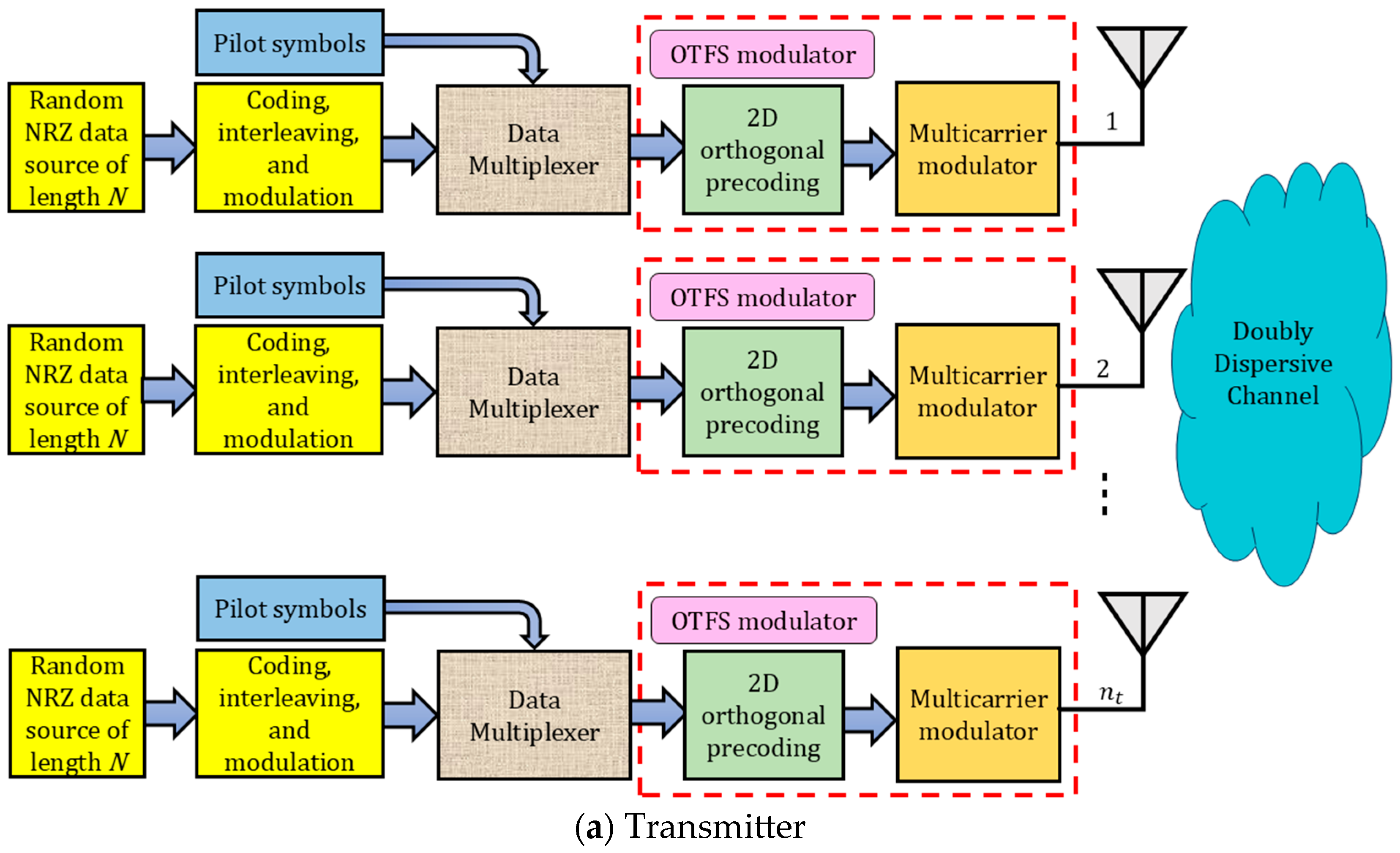
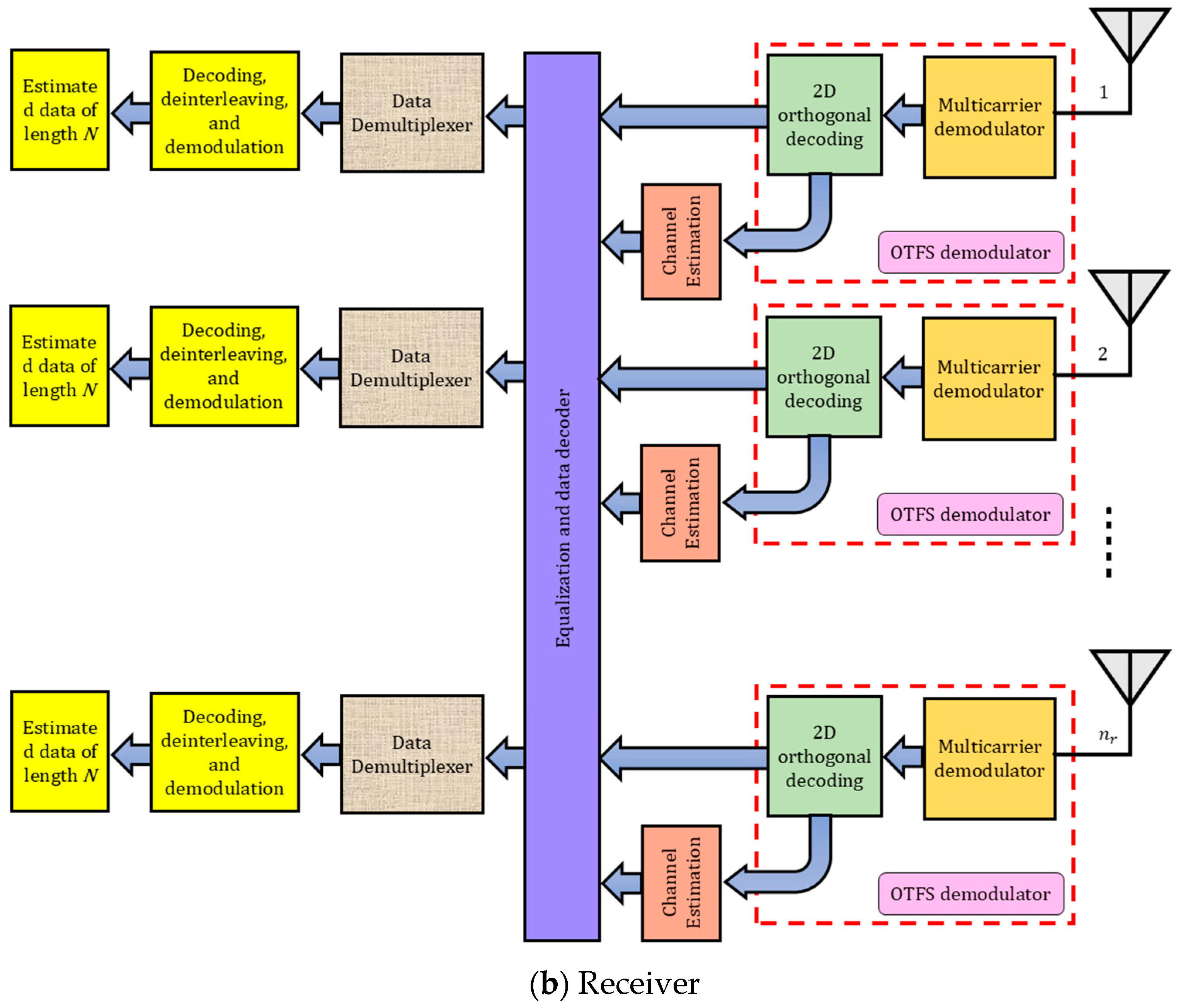
This section details the comprehensive baseband signal model for a MIMO-OTFS communication framework deployed over a time- and frequency-selective wireless channel. The transceiver chain begins with the generation of modulated symbols—either BPSK or QAM—represented by vectors for each transmit antenna . These data streams are then processed through OTFS modulation, implemented using two-dimensional linear canonical transforms. Signal transmission occurs via circular convolution with the time-varying multipath channel, followed by OTFS demodulation at each of the receive antennas. Final symbol detection is achieved using equalization techniques.
Figure 1 illustrates the block architecture of an MIMO-OTFS transceiver system, where and represent the number of transmitting and receiving antennas, respectively. Operating in environments with significant Doppler shifts and multipath delays, the system leverages OTFS modulation to map data symbols into the delay-Doppler domain. This transformation enhances robustness against channel variations. The block diagram encapsulates the parallel processing of multiple input streams, highlighting the synergy between spatial multiplexing in MIMO and the resilience of OTFS against doubly dispersive channel effects. Together, these techniques enable more reliable and efficient wireless communication in dynamic propagation environments.
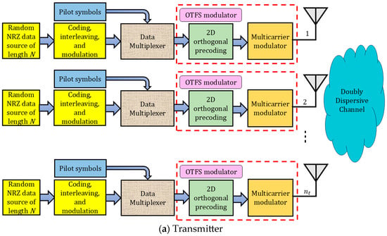
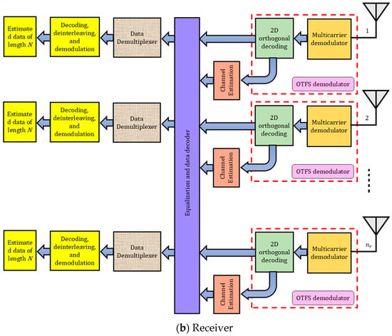
Figure 1.
Block diagram of an MIMO-OTFS system operating over a doubly dispersive channel.
3.1. Delay-Doppler Symbol Mapping and Modulation
Let , for each , represent a two-dimensional array of modulation symbols positioned in the delay-Doppler domain, where is the total number of transmitted antennas. These symbols, selected from a discrete modulation set such as QAM, serve as the input to the OTFS modulation process.
To generate the corresponding time-domain signal , the system first applies the Inverse Symplectic Finite Fourier Transform (ISFFT) to the delay-Doppler grid, followed by transmit pulse shaping. This procedure is carried out using a combination of Discrete Fourier Transform (DFT)-based operations and windowing functions tailored to the transmitter’s characteristics as follows:
In this formulation, denotes the DFT matrix applied along the delay dimension, and represents the Kronecker product. The matrix corresponds to the transmit pulse shaping operation, which is typically set to the identity matrix in the case of rectangular pulse shaping. The matrix is converted into a column vector of size through column-wise vectorization, denoted as .
This transformation converts the signal from the delay-Doppler representation to the time-frequency domain. Subsequently, the application of the pulse shaping function, inherently linked to the Heisenberg transform, yields the final time-domain waveform. By dispersing symbols across both time and frequency axes, the resulting signal structure offers robust performance in channels affected by both multipath delay and Doppler spread, enhancing resilience to dynamic channel impairments.
3.2. Transmission over the Doubly Dispersive Channel
The time-domain OTFS signal is transmitted over a doubly dispersive Linear Time-Varying (LTV) channel, modeled with multiple distinct propagation paths. Each path is characterized by a complex channel coefficient , a discrete delay index , and a normalized Doppler shift .
The received signal is expressed as a linear convolution of the transmitted waveform with the channel’s time-varying impulse response, capturing the joint effects of delay and Doppler introduced by the wireless propagation environment. Hence, the received vector can be expressed as:
where is the received signal vector at the receive antenna, where , and is the total number of receive antennas. The noise component represents complex Gaussian noise with zero-mean and variance at the receive antenna. The matrix denotes the effective channel response between the transmit antenna and the receive antenna, and is defined as follows:
In this formulation, denotes a diagonal matrix that introduces the Doppler-induced frequency shift, defined as for . The matrix represents a circulant delay operator corresponding to a left circular shift by samples. The resulting channel matrix , constructed using a superposition of these operators, captures the combined effects of delay and Doppler dispersion, effectively modeling the wireless channel as a finite sum of different discrete paths. Each path is parameterized by a delay , a Doppler shift , and a complex path gain , corresponding to scattering or reflection from moving objects in the environment. Due to the resolution limits of digital processing, the continuous delay and Doppler values are quantized into discrete indices: and , where and are the system’s sampling period and sampling rate, respectively. Under the assumption that the wireless channel is under-spread, meaning the product of maximum delay and Doppler spreads , the channel can be considered approximately time-invariant over a symbol duration in the delay-Doppler domain. This enables the approximation of the true linear time-varying convolution as a circular convolution, modeled compactly using Doppler-modulated shift matrices. This structure leads to a circulant form of the effective channel matrix , allowing for computationally efficient implementations via the Fast Fourier Transform (FFT). Moreover, this representation supports diagonalization under appropriate unitary bases, paving the way for low-complexity equalization and channel estimation techniques.
3.3. OTFS Demodulation in the Delay-Doppler Domain
The received signal undergoes an initial receive-side pulse shaping operation, represented by the matrix , which is typically selected to match the transmit shaping matrix . Following this, the signal is demodulated using the Symplectic Finite Fourier Transform (SFFT), yielding the output in the delay-Doppler domain as
As a result, we have
The effective OTFS channel matrix , representing the link between the transmit antenna and the receive antenna in the delay-Doppler domain, is defined as
The matrix characterizes the mapping of the time-varying, frequency-selective channel into the delay-Doppler domain. When fractional Doppler shifts are present, the channel response exhibits Doppler-domain leakage, leading to inter-block interference. This effect can be addressed through sophisticated receiver algorithms designed to suppress or compensate for such leakage.
3.4. Equalization Procedure
To estimate the transmitted symbol vector in a general MIMO-OTFS framework with transmit antennas and d receive antennas, a DFE estimator is utilized. Let represent the estimated symbol vector. The signals received from all antennas are concatenated into a single observation vector . The corresponding equivalent channel matrix captures the combined effects of OTFS modulation and the underlying time-varying MIMO channel. The general form of the MIMO-OTFS channel matrix is expressed as:
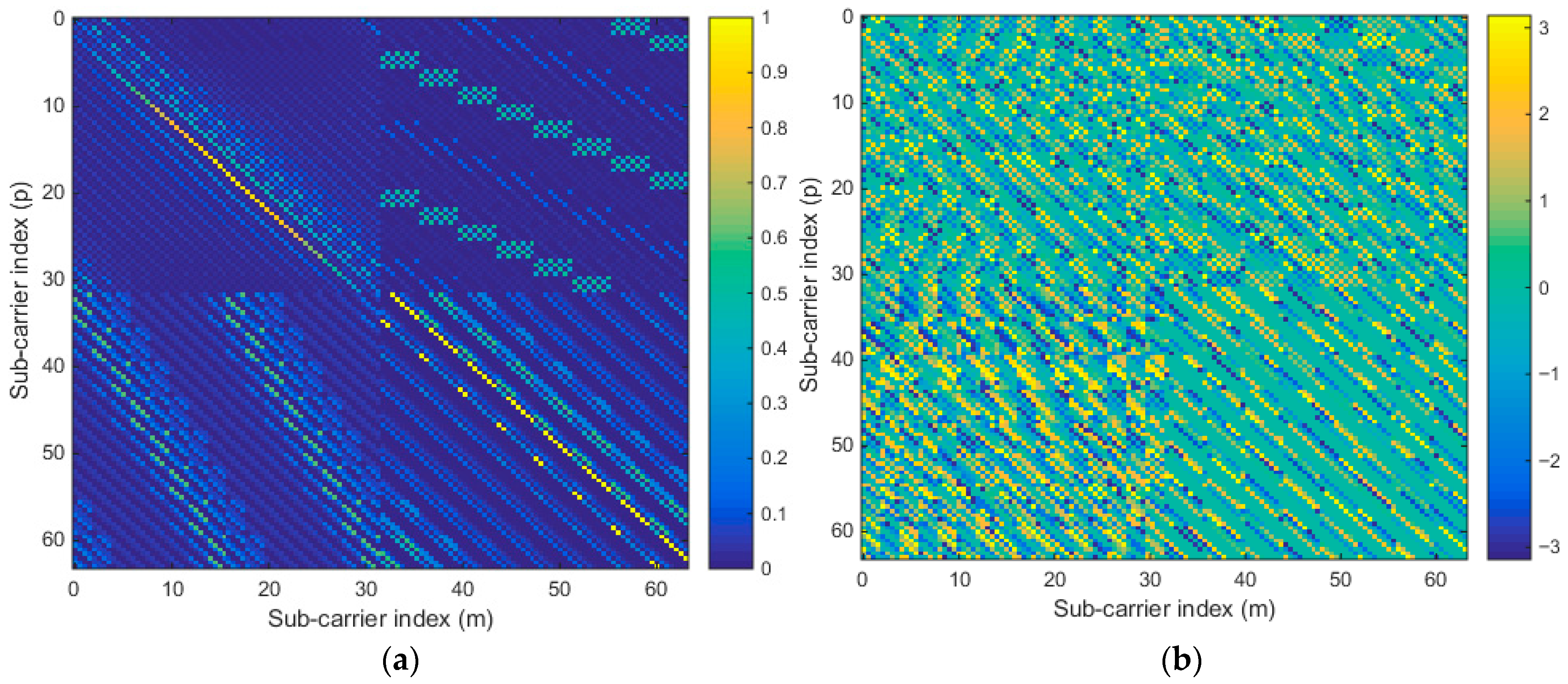
Figure 2a,b depict the average magnitude and phase, respectively, of the Composite Channel Matrix (CCM) associated with , as defined in Equation (7), for a 2 × 2 MIMO system. The CCM offers a detailed characterization of the input–output behavior in the delay-Doppler domain within the MIMO-OTFS framework. It is evident from the visualizations that the matrix exhibits a near full-rank structure, reflecting substantial inter-symbol interactions across spatial and delay-Doppler dimensions. This dense coupling poses a significant obstacle to the application of the Banded Matrix Approximation (BMA) method [32], which seeks to lower equalization complexity by leveraging sparsity or localized interference patterns. However, the observed widespread energy distribution in the CCM indicates that most entries contribute meaningfully, thus limiting the potential efficiency gains of BMA in this context.
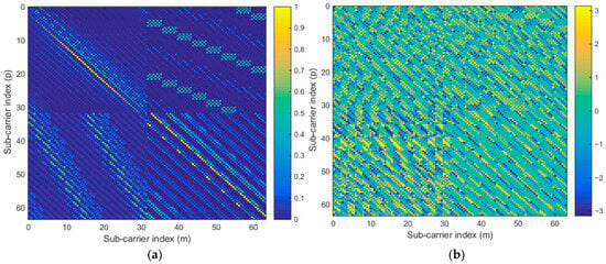
Figure 2.
(a) Average magnitude and (b) Phase of the CCM corresponding to for a 2 × 2 MIMO configuration.
The Minimum Mean Square Error Decision Feedback Equalizer (MMSE-DFE) with regularized QR filtering matrix is subsequently applied to the received signal vector, as specified in Equation (5), to counteract the impairments introduced by the doubly dispersive wireless channel and to recover the transmitted data vector. The MMSE-DFE approach applies regularized QR decomposition to account for noise in the estimation process. Define the noise variance as , typically derived from the SNR. The augmented system is constructed as follows:
where is a unitary matrix, and is upper triangular. Next, form the augmented received vector and compute the transformed observation as:
The symbol estimates are then obtained by backward substitution on , accounting for previously detected symbols to cancel interference as follows:
Here, the sign function denotes hard decisions, assuming BPSK modulation (mapping to ).
3.5. Throughput Calculation
The effective number of correctly decoded bits in a transmission can be calculated with the formula:
In this expression, is the total number of bits sent in each iteration, and is the number of bits that were received incorrectly due to transmission impairments. The parameter represents the number of bits encoded in each symbol, a value that varies with the modulation technique. To assess the data throughput of the communication system, we scale Equation (11) by the symbol rate , which measures how many symbols are transmitted per second:
This formula encapsulates the influence of transmission errors, modulation efficiency, and symbol rate. High error rates significantly degrade throughput, while increasing (through higher-order modulation) or (by increasing bandwidth or reducing symbol duration) can enhance performance, provided the channel conditions remain favorable.
3.6. Complexity Calculation
We now evaluate the computational complexity, in terms of the number of operations, of the proposed MMSE-DFE for a general -MIMO configuration. The first step involves constructing the regularized QR decomposition by augmenting the channel matrix with noise weighting, as shown in Equation (8), to obtain the and matrices. Next, the Hermitian transpose of is multiplied by the received vector, which requires operations [5]. This is followed by the back-substitution and hard-decision process using BPSK modulation, as expressed in Equation (10).
The back-substitution loop runs from down to 1, executing iterations in total. In each iteration, the first operation computes a dot product between part of the matrix row and the vector , requiring complex multiplications and complex additions. The subsequent operation performs one subtraction and one division per iteration. Summing up all iterations, the total number of complex multiplications equals , while the total number of complex additions equals . In addition, there are complex subtractions and divisions.
In fact, one complex multiplication corresponds to six real operations, and one complex addition or subtraction corresponds to two real operations [5], with each division counting as one operation, the total number of operations for Equation (10) is given by:
Therefore, the overall computational complexity of the proposed MMSE-DFE can be expressed as:
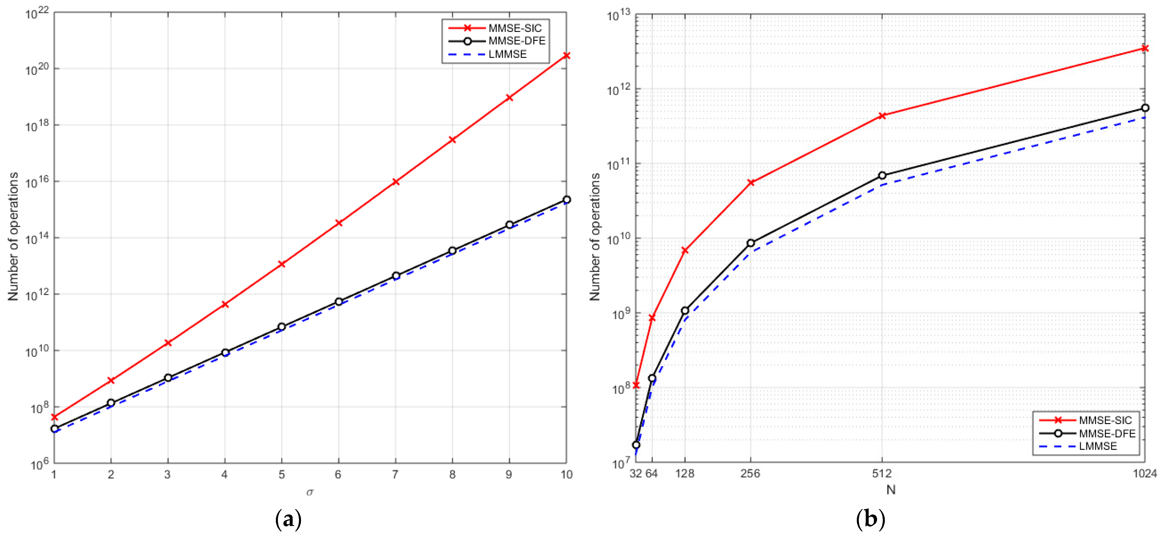
Figure 3 shows the computational complexity of LMMSE and nonlinear equalizers, including the proposed MMSE-DFE and MMSE-Successive Interference Cancellation (MMSE-SIC) [4], across different MIMO sizes and subcarrier lengths. As increases from 1 to 10, the number of operations grows for all algorithms as depicted in Figure 3a. MMSE-SIC exhibits the steepest increase, reaching nearly operations for , which may become impractical for large-scale MIMO systems. In contrast, the proposed MMSE-DFE demonstrates a more moderate growth, requiring approximately operations at , slightly above LMMSE () but orders of magnitude lower than MMSE-SIC, indicating a more scalable solution. When examining subcarrier length for , all algorithms show increasing complexity with , yet MMSE-SIC again dominates the computational load as depicted in Figure 3b. Specifically, for , MMSE-SIC reaches operations, while MMSE-DFE and LMMSE require and , respectively. These trends highlight that while nonlinear equalizers generally provide superior interference cancellation, their complexity can be prohibitive. The proposed MMSE-DFE strikes a balance, offering significant interference mitigation with much lower computational cost than MMSE-SIC, making it more suitable for practical implementations. Importantly, nonlinear algorithms should be compared primarily with each other rather than with linear methods like LMMSE, as the latter operate under different complexity–performance trade-offs. Overall, the results confirm that the proposed MMSE-DFE achieves an effective compromise between performance and complexity, particularly for systems with large MIMO sizes or high subcarrier counts.
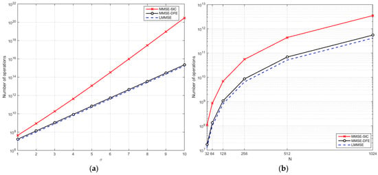
Figure 3.
Operations count versus (a) MIMO configuration (b) sub-carrier length .
4. Simulation Results and Analysis
This section provides an in-depth performance assessment of the proposed 2 × 2 MIMO-OTFS system, benchmarked against a traditional MIMO-OFDM setup via Matlab software (2024b). The evaluation emphasizes key performance metrics such as BER, SNR gains, and overall throughput. The primary objective is to demonstrate the resilience and efficiency of the OTFS-based transceiver architecture when subjected to realistic wireless channel conditions, particularly those exhibiting doubly dispersive fading and additive white Gaussian noise. To ensure a fair comparison, both OTFS and OFDM systems are implemented within a unified simulation environment. Each system employs a transform size of 64, corresponding to the number of subcarriers in the modulation scheme. In the OFDM system, a Cyclic Prefix (CP) of length 16 is appended to each symbol to mitigate ISI. The simulation spans a range of SNR values from 0 dB to 30 dB in 5 dB steps, enabling a comprehensive analysis across varying channel qualities.
The multipath channel is modeled using a configurable number of scatterers, from 1 to 15 paths, to replicate the diversity of real-world propagation environments. System-level parameters include a 4 GHz carrier frequency and a total bandwidth of 1 MHz. The modulation format is BPSK to evaluate modulation-specific performance characteristics. The MIMO architecture consists of two transmit and two receive antennas , consistent with common spatial multiplexing configurations. Additionally, the delay spread is captured using a maximum delay index of 16, and the Doppler effect is modeled through a normalized Doppler shift of 2, ensuring that the simulation reflects both time and frequency dispersion effects accurately.
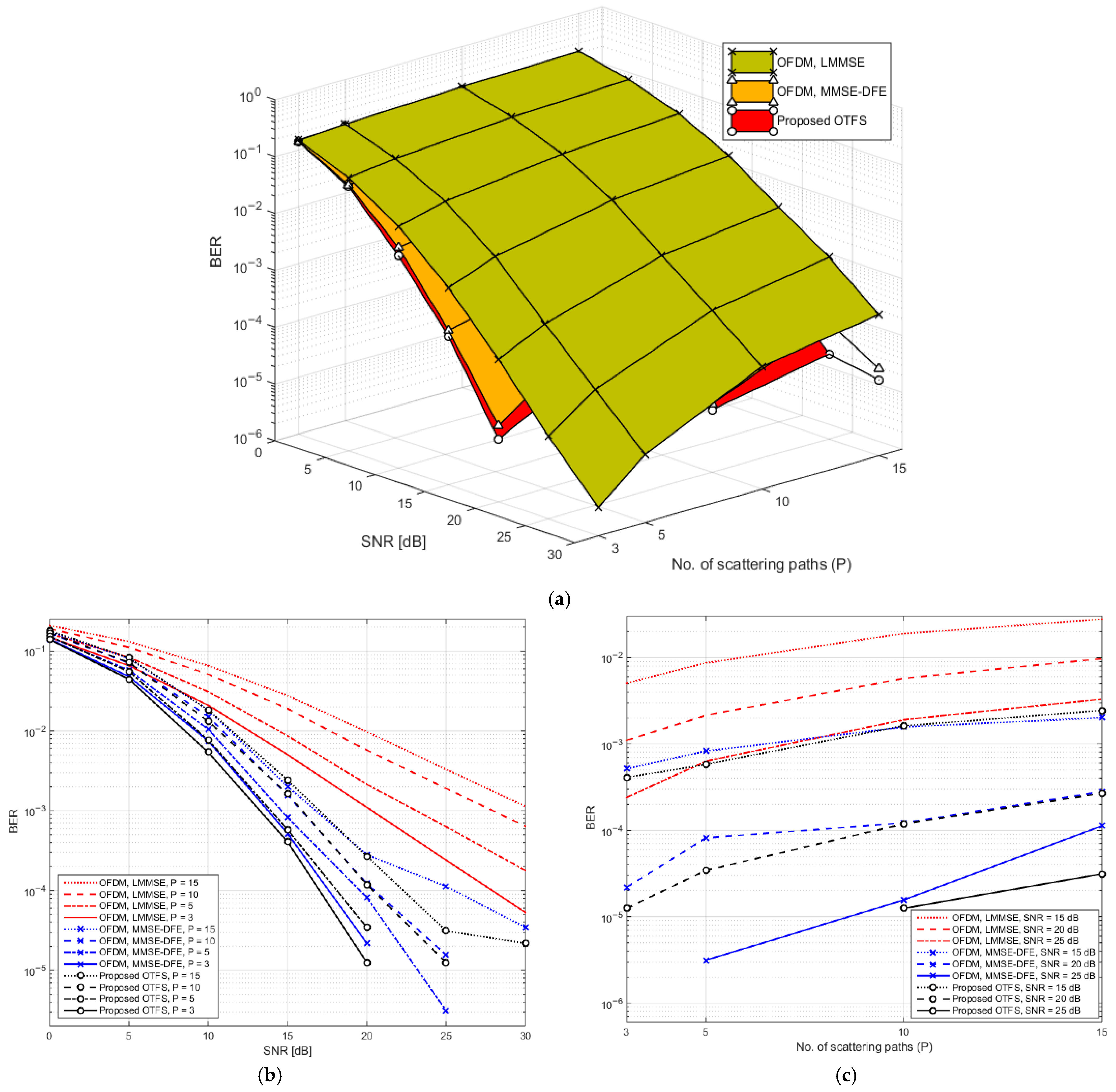
Figure 4a illustrates a three-dimensional surface plot that captures the BER behavior as a function of SNR and the number of multipath components (denoted as ). The figure compares the performance of the proposed MIMO-OTFS system utilizing MMSE-DFE equalization against a conventional MIMO-OFDM system implemented with MMSE-DFE and LMMSE techniques. This visual representation effectively conveys the dynamic interplay between channel richness and noise levels, providing insight into system robustness across varying propagation conditions. As evident in the plot, the BER tends to decrease with increasing SNR, a trend consistent with improved signal fidelity at higher power levels. Conversely, an increase in the number of channel scattering paths leads to higher BER values, reflecting the detrimental impact of ISI in richly scattered environments—especially under doubly dispersive channel conditions. This performance degradation is particularly challenging for conventional systems like OFDM, which are more susceptible to delay and Doppler spread. To further clarify the behavior observed in the 3D plot, Figure 4b,c present two-dimensional projections. Figure 4b offers an elevation perspective, emphasizing BER variations with respect to SNR across different values of . It clearly shows that as the number of scattered paths increases, the performance gap between the proposed OTFS system and traditional OFDM widens. This underscores the enhanced robustness of OTFS in handling severe multipath and time-frequency dispersion. Figure 4c, presents a side-view projection, focusing on how BER responds to changes in the number of scattering paths at fixed SNR levels. This perspective highlights the sensitivity of each modulation scheme to channel complexity, reinforcing the advantage of the OTFS-based approach in highly dynamic and dispersive environments.
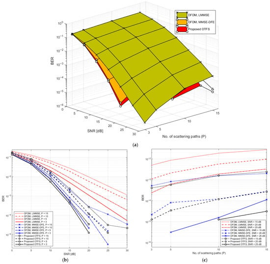
Figure 4.
(a) 3D plot of BER as a function of SNR and scattering path count for OTFS and OFDM Systems. (b) Elevation view of (a). (c) Side view of (a).
The numerical results presented in Table 2 detail the BER performance of the proposed MIMO-OTFS system compared to conventional MIMO-OFDM systems (employing MMSE-DFE and LMMSE equalizers) across different SNR levels and varying numbers of scattered channel paths . The table clearly shows that the proposed OTFS system consistently outperforms both OFDM variants, especially under more severe multipath conditions. As the number of paths increases, performance degradation is more pronounced for the OFDM systems, particularly the LMMSE variant, highlighting the OTFS system’s superior resilience to channel dispersion.

Table 2.
Impact of the number of scattered paths on BER performance over SNR for OTFS and OFDM systems.
At lower SNR (10 dB), the OTFS system achieves a BER of with , which remains significantly lower than OFDM-MMSE-DFE and especially OFDM-LMMSE . As SNR increases, all systems show improved BER, but the OTFS system demonstrates steeper gains. For example, at 20 dB and , OTFS achieves a BER of , outperforming OFDM-MMSE-DFE and drastically surpassing OFDM-LMMSE . At 25 and 30 dB, OTFS approaches near-zero error rates even under challenging conditions (e.g., ), whereas OFDM systems, especially LMMSE, continue to suffer measurable BER. These results underscore the proposed OTFS system’s robustness and efficiency in handling time- and frequency-selective fading, making it particularly well-suited for high-mobility or high-multipath wireless environments.
The Outage Probability (OP) represents the likelihood that the instantaneous Signal-to-Interference Noise Ratio (SINR) of a wireless link falls below a predefined threshold, indicating that reliable communication cannot be maintained. It is an important performance metric in doubly dispersive and fading channels, as it captures both the effects of channel fading and noise. Mathematically, the outage probability is defined as:
where denotes the instantaneous SINR and is the target SINR threshold required to achieve a specified quality of service. In simulations, the outage probability is estimated by counting the fraction of channel realizations in which the instantaneous SINR falls below .
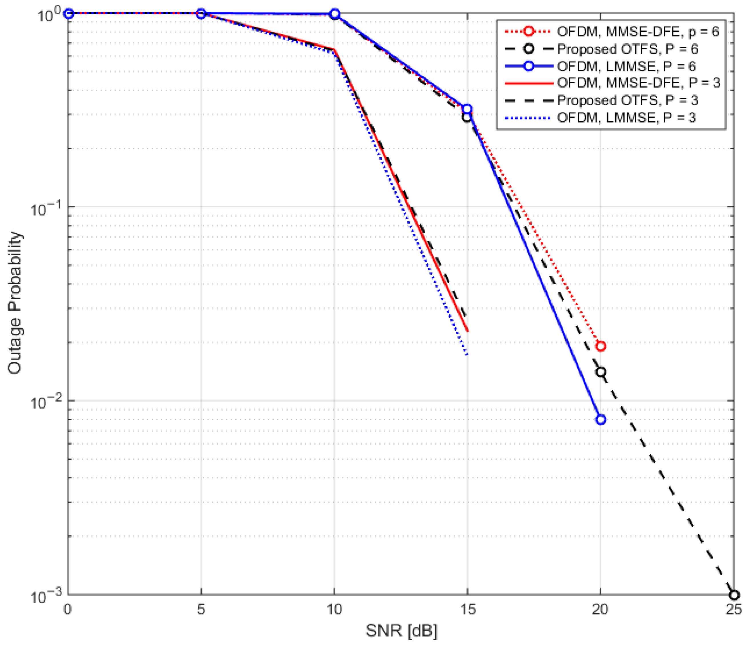
Figure 5 presents a detailed comparison of the outage probability for the proposed OTFS scheme and the conventional OFDM scheme. The plot shows how the outage probability evolves with respect to varying SNR values for both schemes. From the figure, it is evident that the outage probabilities of OTFS and OFDM remain quite comparable across the entire SNR range. Both schemes exhibit similar trends as the SNR increases, suggesting that the proposed OTFS scheme performs similarly to OFDM in terms of outage probability, even in the presence of challenging channel conditions such as multi-path fading and Doppler shifts.
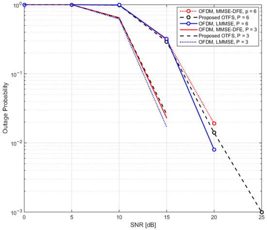
Figure 5.
Outage probability vs. SNR for various schemes.
This outcome highlights that while OTFS leverages advanced techniques for mitigating time-frequency dispersion in the channel, its outage performance is on par with the established OFDM scheme, providing strong evidence of OTFS’s potential for reliable communication in scenarios with varying SNR. Thus, both schemes offer comparable robustness to signal degradation in terms of outage probability, making OTFS a competitive candidate for modern wireless communication systems.
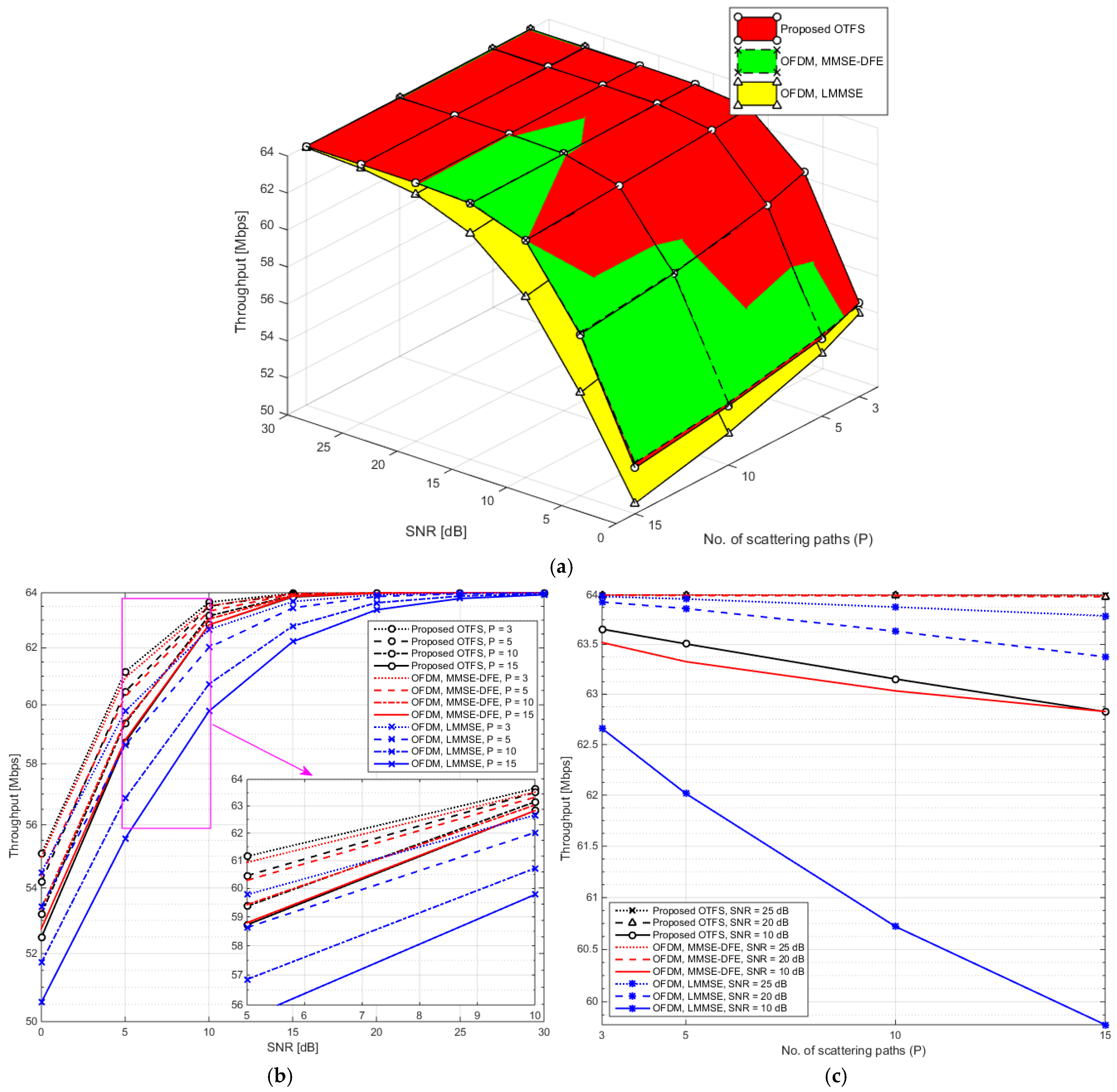
Figure 6a presents a three-dimensional surface plot depicting the throughput performance of the proposed MIMO-OTFS system in comparison with a conventional MIMO-OFDM system, both evaluated over varying SNR and different numbers of multipath components (). This visualization provides a comprehensive perspective on how each system handles the combined challenges of noise and channel dispersion. Unlike BER, which reflects error rates, throughput serves as a direct indicator of how efficiently data can be transmitted, making it a practical measure of system effectiveness. As observed in the 3D plot, throughput increases with rising SNR for both systems, aligning with expectations due to enhanced signal clarity. However, the proposed MIMO-OTFS consistently delivers higher throughput, particularly in moderate to high SNR regions. This performance gap becomes increasingly pronounced as the number of scattered paths grows, reflecting OTFS’s superior resilience to delay and Doppler effects. While both systems experience a slight throughput decline with increasing , due to more severe time-frequency dispersion, OTFS sustains performance significantly better, indicating its robustness in challenging environments. To provide a clearer breakdown of these trends, Figure 6b offers an elevation view of the same dataset, showing how throughput evolves with increasing SNR across various values. This view reveals that at lower SNR and simpler channel conditions (e.g., small ), the performance of both systems is comparable. However, as either SNR or path complexity increases, the proposed OTFS begins to clearly outperform OFDM, particularly in scenarios with significant multipath—a common occurrence in dense urban or mobile contexts. Figure 6c provides a side perspective, isolating throughput behavior as a function of the number of scattered paths for various SNR levels. This angle emphasizes how the proposed OTFS exhibits much slower degradation in throughput as channel dispersion increases. The observed trend reinforces earlier conclusions: proposed OTFS not only achieves more reliable communication in dispersive environments (as reflected in the BER analysis) but also sustains higher data rates, making it a compelling choice for next-generation wireless systems operating under high mobility or complex propagation conditions.
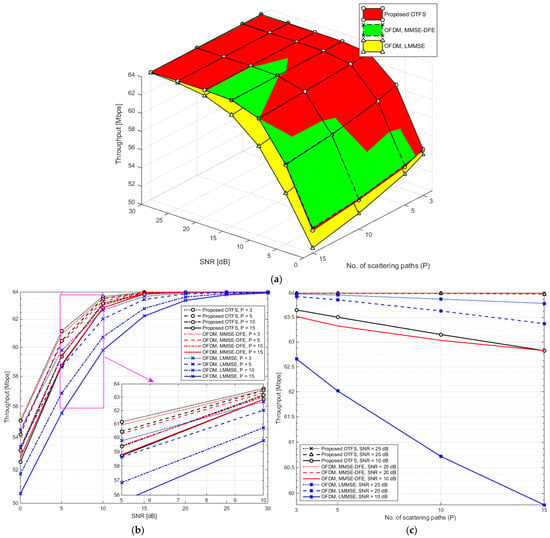
Figure 6.
(a) 3D plot of throughput as a function of SNR and scattering path count for OTFS and OFDM Systems. (b) Elevation view of (a). (c) Side view of (a).
Table 3 presents the throughput performance (in Mbps) of the proposed MIMO-OTFS system compared to conventional MIMO-OFDM systems using MMSE-DFE and LMMSE equalization across different SNR values and varying numbers of scattered channel paths (). The data provides valuable insight into how each system handles the joint challenges of noise and multipath dispersion, particularly in terms of sustaining data rates under adverse channel conditions. At a lower SNR of 10 dB, the proposed OTFS demonstrates a clear throughput advantage, maintaining up to 63.65 Mbps at , and only slightly decreasing to 62.83 Mbps at . In contrast, OFDM with LMMSE shows a more noticeable degradation, from 62.22 Mbps to 59.78 Mbps, which indicates its reduced ability to cope with increased multipath effects. At higher SNRs (20 dB and above), all systems approach peak throughput (near 64 Mbps), but proposed OTFS consistently shows minimal sensitivity to increasing , retaining perfect or near-perfect throughput even at . OFDM-LMMSE, while improved at high SNR, still lags slightly behind the proposed OTFS and OFDM-MMSE, particularly as grows. Overall, the results confirm that the proposed OTFS maintains high throughput more effectively than OFDM, especially in dispersive environments, which makes it better suited for scenarios with rich multipath and high mobility. Its ability to preserve data rates with minimal degradation across a range of challenging channel conditions is a key advantage for next-generation wireless communication systems.

Table 3.
Impact of the number of scattered paths on throughput over SNR for OTFS and OFDM systems.
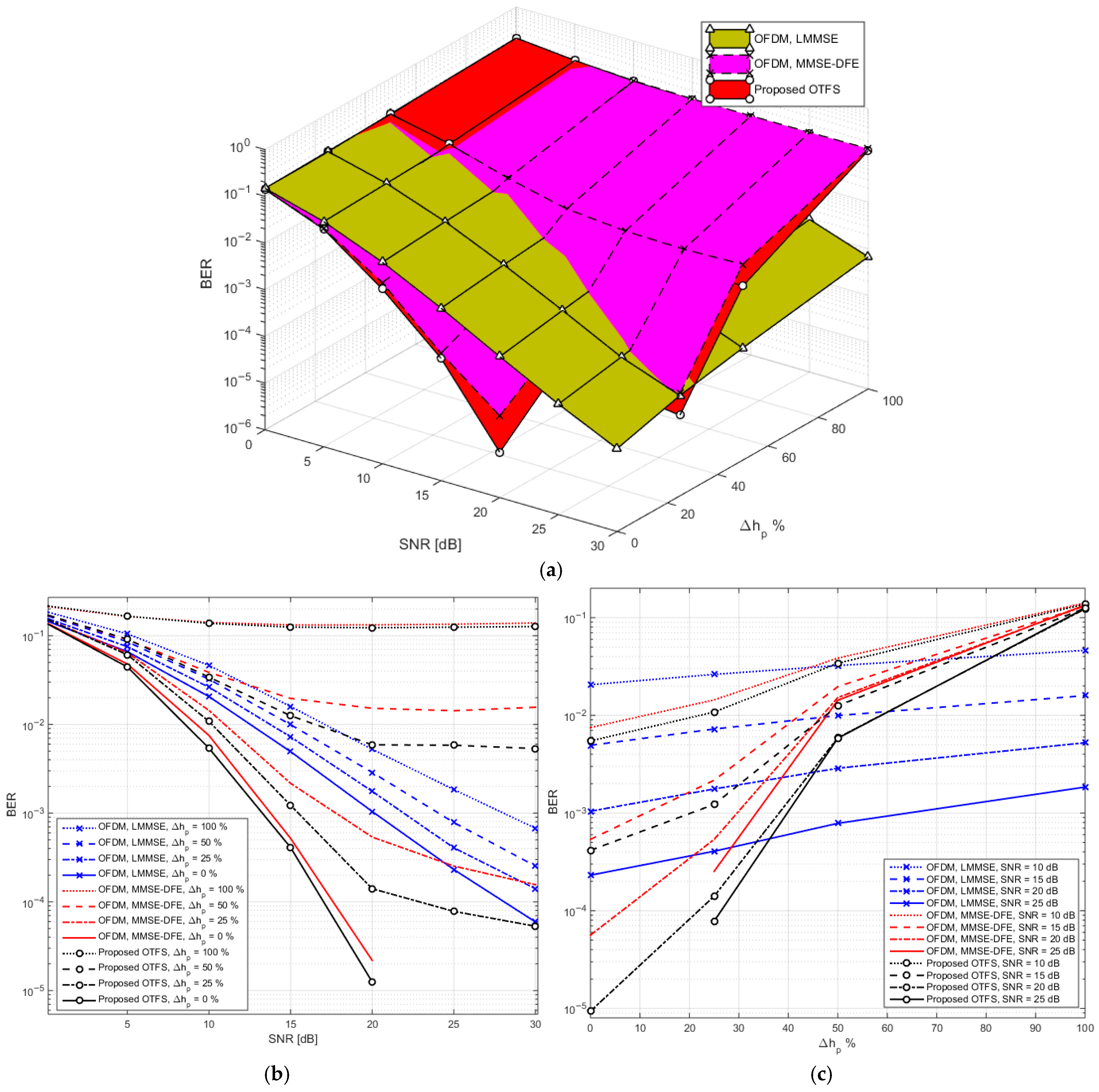
Figure 7 offers a comprehensive visualization of BER performance as a function of SNR and the percentage of channel estimation error for the proposed OTFS system in comparison to conventional OFDM schemes, specifically those employing LLMMSE and MMSE-DFE. The figure comprises three perspectives: (a) a 3D surface plot, (b) an elevation view, and (c) a side view. In Figure 7a, the 3D surface plot distinctly shows that the BER of the proposed OTFS system remains significantly lower than that of the OFDM-based schemes, particularly when the estimation error percentage is less than 25%. As both SNR and estimation error vary, the OTFS system demonstrates stronger resilience, maintaining lower BER values under a wider range of conditions. Importantly, the OFDM system utilizing LMMSE shows a more gradual and consistent variation in BER across increasing estimation errors. While its absolute BER performance is generally inferior to OTFS when the estimation error is below 25%, the slow variation becomes an advantage in scenarios where estimation inaccuracies fluctuate, contributing to more predictable performance. In Figure 7b, the elevation aligns along the BER-SNR plane, revealing the system behavior across increasing SNR levels for a fixed estimation error. Figure 7c, the side view of the 3D plot, emphasizes how BER shifts with increasing estimation error across different SNR values. This view reinforces the observation that the proposed OTFS offers lower BER in low to moderate estimation error conditions, especially below the 25% threshold. Beyond this point, while OTFS performance degrades more sharply, the LMMSE-based OFDM exhibits smoother transitions, indicating better stability under severe channel uncertainty, albeit with consistently higher BER.
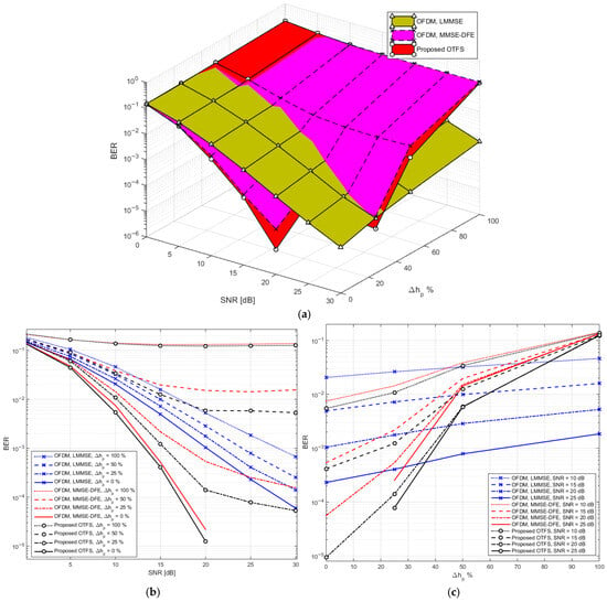
Figure 7.
(a) 3D plot of BER vs. SNR and channel estimation error percentage for proposed OTFS and OFDM. (b) Elevation view of (a). (c) Side view of (a).
Table 4 presents a quantitative analysis of BER across a range of SNR values (from 10 dB to 30 dB) and channel estimation error percentages (0%, 25%, 50%, and 100%) for the proposed OTFS system and two OFDM systems (LMMSE and MMSE-DFE). At lower SNR levels, such as 10 dB, the proposed OTFS system already demonstrates superior BER performance under ideal channel estimation (0% error), achieving a BER of , outperforming both OFDM variants. Notably, the OFDM system with LMMSE, while yielding a higher BER of , displays a slower rate of degradation as estimation error increases. This stability can be beneficial in environments where the channel estimation is less reliable or fluctuates unpredictably. However, in scenarios where the estimation error remains below 25%, OTFS provides a clearly better performance margin. At 15 dB SNR, the proposed OTFS maintains its advantage in low-error conditions, achieving a BER of just at 0% error, and remaining ahead of OFDM across all error percentages. Still, the LMMSE-based OFDM system again demonstrates smoother BER degradation, varying from to , in contrast to the sharper performance decline seen in OTFS beyond the 25% error level.

Table 4.
BER vs. SNR for different modulation schemes in the proposed OTFS and OFDM systems.
The trend continues at 20 dB, where the proposed OTFS achieves near-error-free performance under perfect estimation and maintains a moderate BER of even at 50% error. In comparison, OFDM-MMSE-DFE exhibits a more dramatic rise in BER under the same error conditions, while OFDM-LMMSE, though less accurate, degrades more gradually—from at 0% error to at 100% error, reinforcing its predictable but conservative performance trend. At higher SNR levels (25 dB and 30 dB), the proposed OTFS reaches zero BER under ideal channel estimation, maintaining strong performance at 25% error ( and , respectively). At 50% error, BER remains relatively low (around ), although a more noticeable decline in performance is observed at 100% error. OFDM-MMSE-DFE, although sometimes matching OTFS under ideal estimation, rapidly deteriorates at higher error percentages. OFDM-LMMSE, on the other hand, consistently performs at a moderate level, neither achieving the low BER of OTFS under optimal conditions nor suffering the drastic degradation of MMSE-DFE under severe estimation errors.
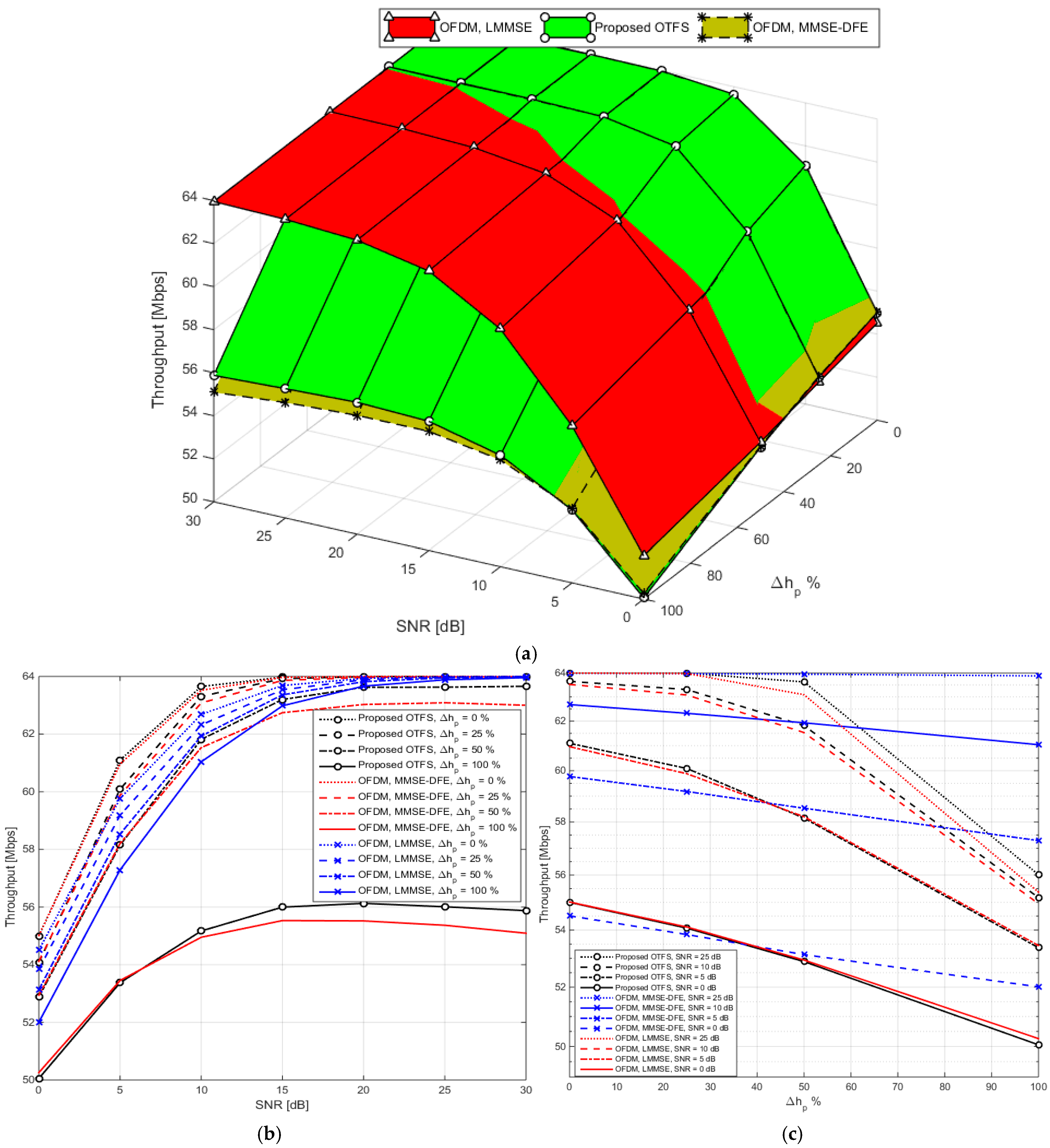
Figure 8 presents a visual analysis of system throughput as a function of SNR and channel estimation error percentage for the proposed OTFS system and two OFDM variants, OFDM with LMMSE equalization and OFDM with MMSE-DFE. The figure is divided into three subplots: (a) a 3D surface plot, (b) an elevation view, and (c) a side view of the same data. In Figure 8a, the 3D surface plot clearly reveals that the proposed OTFS system maintains consistently high throughput when the channel estimation error is low (0% to 25%). As estimation errors increase beyond 50%, the throughput of OTFS begins to decline more sharply than that of OFDM with LMMSE, although it remains relatively robust. The OFDM-LMMSE surface, in contrast, shows only minimal variation with increasing estimation errors. This gentle slope indicates that OFDM-LMMSE is less sensitive to degradation from imperfect channel estimation, a beneficial trait in scenarios with high or unpredictable estimation uncertainty. Figure 8b, the elevation view, accentuates how throughput changes with channel estimation error across a range of SNRs. The proposed OTFS system exhibits a more noticeable decline in throughput when the estimation error increases from 0% to 100%, especially at lower SNRs (e.g., 10–15 dB). In contrast, OFDM with LMMSE shows nearly flat lines, meaning it sustains its performance even with severe estimation inaccuracies. This suggests that while OTFS excels in more controlled environments with accurate channel estimation, OFDM-LMMSE offers greater stability under deteriorating channel knowledge. Figure 8c, which offers a side view along the throughput-SNR plane, makes it evident that all systems reach a saturation throughput level at high SNRs when estimation error is minimal. However, OTFS stands out for delivering near-maximal throughput even at moderate SNRs (around 15–20 dB), provided that the estimation error remains under 25%. OFDM-MMSE-DFE, while initially competitive, shows more pronounced throughput degradation with increased estimation error compared to the LMMSE variant, particularly beyond the 50% mark.
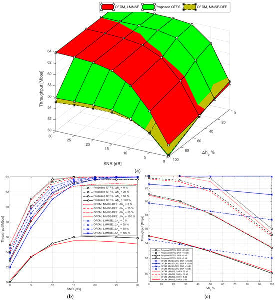
Figure 8.
(a) 3D plot of throughput vs. SNR and channel estimation error percentage for proposed OTFS and OFDM. (b) Elevation view of (a). (c) Side view of (a).
Table 5 offers a numerical breakdown of throughput performance, measured in Mbps, for various SNR levels and estimation error percentages in the systems depicted in Figure 8. The results reinforce the visual trends and provide further insight into system reliability and efficiency under different conditions. At an SNR of 10 dB, the proposed OTFS system achieves a throughput of 63.65 Mbps under perfect channel estimation, slightly outperforming both of the OFDM variants. However, as the estimation error increases, the throughput of the proposed OTFS declines more rapidly, reaching 55.17 Mbps at 100% error. OFDM with LMMSE, on the other hand, displays only minor degradation, from 62.68 Mbps to 61.04 Mbps, demonstrating its strong tolerance to estimation inaccuracies. MMSE-DFE performs similarly to the proposed OTFS in absolute throughput but suffers a sharp drop like OTFS when estimation accuracy deteriorates. At 15 dB, the proposed OTFS shows marginal improvement in throughput, recording 63.97 Mbps at 0% error and 56.00 Mbps at 100%. OFDM-LMMSE again shows minimal sensitivity to channel estimation error, retaining over 62 Mbps even under worst-case conditions. OTFS retains a throughput edge when estimation error is low (e.g., 0–25%), but the advantage diminishes quickly beyond that. When the SNR reaches 20 dB, all systems approach their throughput ceiling. Proposed OTFS records the maximum possible 64.00 Mbps at 0% and remains above 63 Mbps until 50% estimation error. At 100% error, throughput dips slightly to 56.13 Mbps, revealing OTFS’s sensitivity to extreme estimation inaccuracies. OFDM-LMMSE continues to show stable performance, varying within a narrow range (63.93–63.66 Mbps). MMSE-DFE closely tracks the proposed OTFS at low error levels but again drops significantly to 100% error, showing a throughput of just 55.52 Mbps. At 25 dB, a similar pattern continues: OTFS holds steady at 64 Mbps for perfect estimation and 25% error, while dropping slightly to higher errors. OFDM-LMMSE remains nearly constant across all error levels (63.99 to 63.88 Mbps), reinforcing its reliability in adverse conditions. MMSE-DFE continues to demonstrate sharp sensitivity to error beyond 25%. Interestingly, at 30 dB, OTFS delivers an anomalously high throughput of 66.88 Mbps at 100% estimation error—potentially due to system-specific effects like overestimation of throughput caused by adaptive encoding or simulation anomalies. However, under normal conditions (0% to 50% error), the proposed OTFS remains capped at 64 Mbps. OFDM systems maintain their earlier trends, with LMMSE performing steadily (63.96–64.00 Mbps) and MMSE-DFE again falling behind under high estimation error.

Table 5.
Throughput vs. SNR for different channel estimation error percentages in proposed OTFS and OFDM systems.
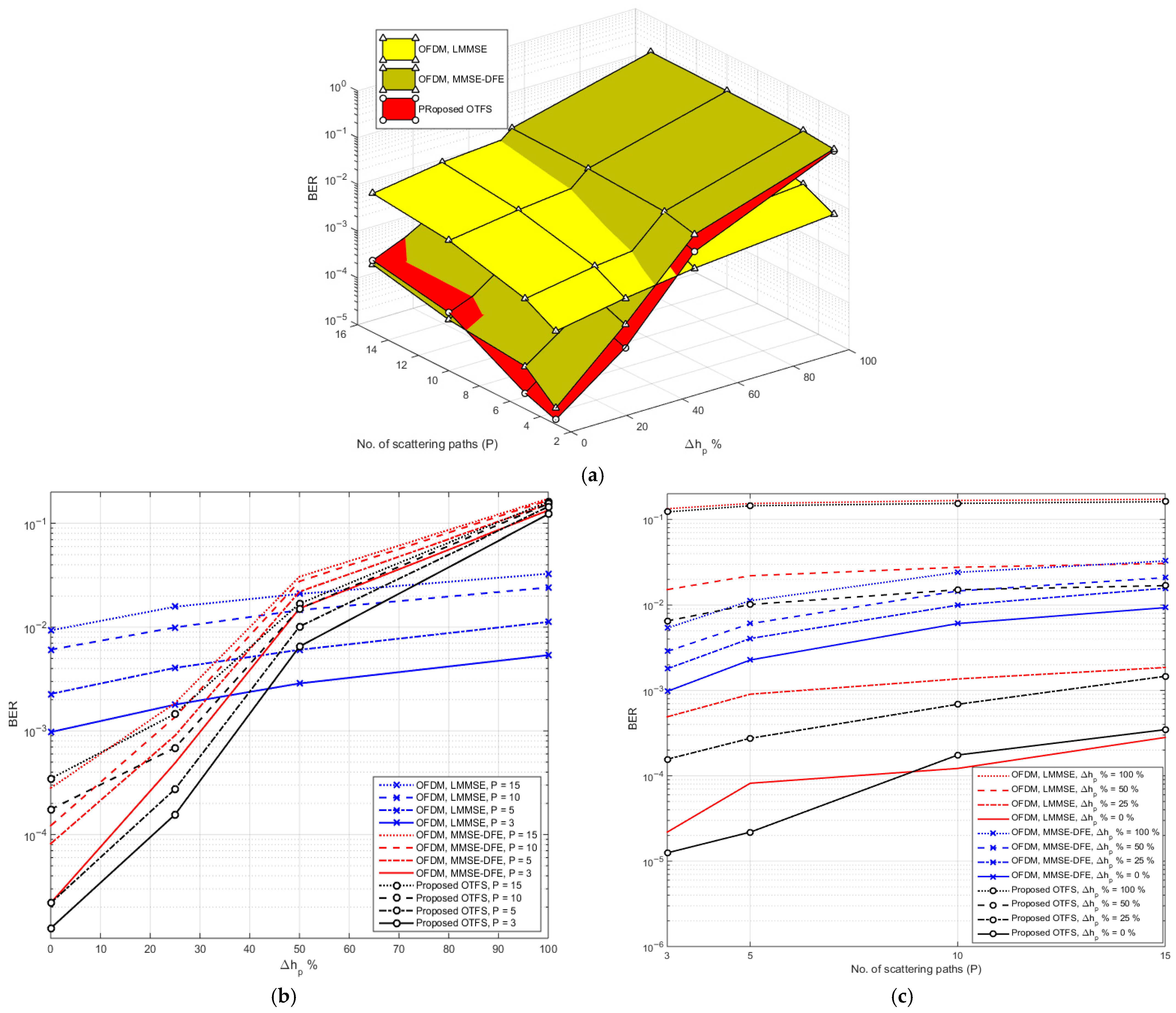
Figure 9a provides a 3D visual analysis of the BER performance for the proposed OTFS and conventional OFDM systems, specifically those utilizing LMMSE and MMSE-DFE equalizers at a fixed SNR of 20 dB. BER is plotted as a function of both the channel estimation error percentage and the number of scattered multipath components (), capturing how the systems behave under varying channel complexity and estimation accuracy. The elevation view (Figure 9b) provides a clearer picture of BER degradation with rising estimation error. It confirms that OFDM-LMMSE maintains a relatively flat curve, reflecting its robustness to channel estimation uncertainty. In contrast, the proposed OTFS starts with an exceptionally low BER but deteriorates more sharply, especially beyond 50% error, suggesting its performance is more reliant on precise channel estimation. In the side view (Figure 9c), the influence of the number of scattered paths is highlighted. As increases from 3 to 15, the BER of all systems rises; however, the rate of BER increase is slowest for OFDM with LMMSE, reinforcing its resilience in rich multipath environments.
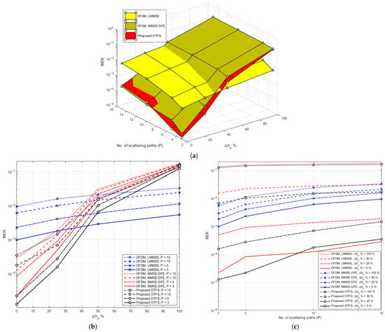
Figure 9.
(a) 3D plot of BER vs. channel estimation error percentage and number of scattered paths for proposed OTFS and OFDM at SNR = 20 dB. (b) Elevation view of (a). (c) Side view of (a).
Table 6 presents the BER values corresponding to the systems illustrated in Figure 9 for different numbers of multipath components ( = 3, 5, 10, 15) and channel estimation error percentages (0%, 25%, 50%, and 100%). These numerical results align with and further quantify the patterns observed in Figure 9. At = 3, the proposed OTFS system achieves a very low BER of under perfect channel estimation, significantly outperforming both OFDM systems. Even with 25% error, the proposed OTFS retains a low BER of , while OFDM with LMMSE and MMSE-DFE report higher values. However, when the estimation error reaches 100%, OTFS BER increases sharply to 0.122. In contrast, OFDM-LMMSE maintains much better stability, with a BER of only at 100% error—worse than OTFS under ideal conditions, but far better under severe estimation inaccuracies. MMSE-DFE, while initially close to the proposed OTFS, suffers a comparable steep degradation. With = 5, the channel becomes more dispersive, and the proposed OTFS begins to show greater sensitivity. Although it still starts strong with a BER of at 0%, its BER rises significantly to 0.144 at 100% error. OFDM-LMMSE again shows smaller absolute BERs than proposed OTFS under poor estimation conditions, rising only from to across the error range. This small variation underscores its robustness to both path increase and estimation error, albeit at the cost of a higher BER than proposed OTFS when estimation is accurate. MMSE-DFE exhibits even sharper degradation, reaching 0.154 BER at 100% error. When = 10, the proposed OTFS’s BER increases across all error levels, starting at and rising to 0.154. OFDM-LMMSE continues to exhibit smaller variation, with BER ranging from to . At = 15, the trend continues. OTFS’s BER reaches its worst values, from at 0% error to 0.161 at 100%. Meanwhile, OFDM-LMMSE scales from to only , showcasing remarkable consistency in performance despite increased multipath complexity and estimation degradation.

Table 6.
BER vs. Channel error estimation percentage for different numbers of scattered paths in proposed OTFS and OFDM systems.
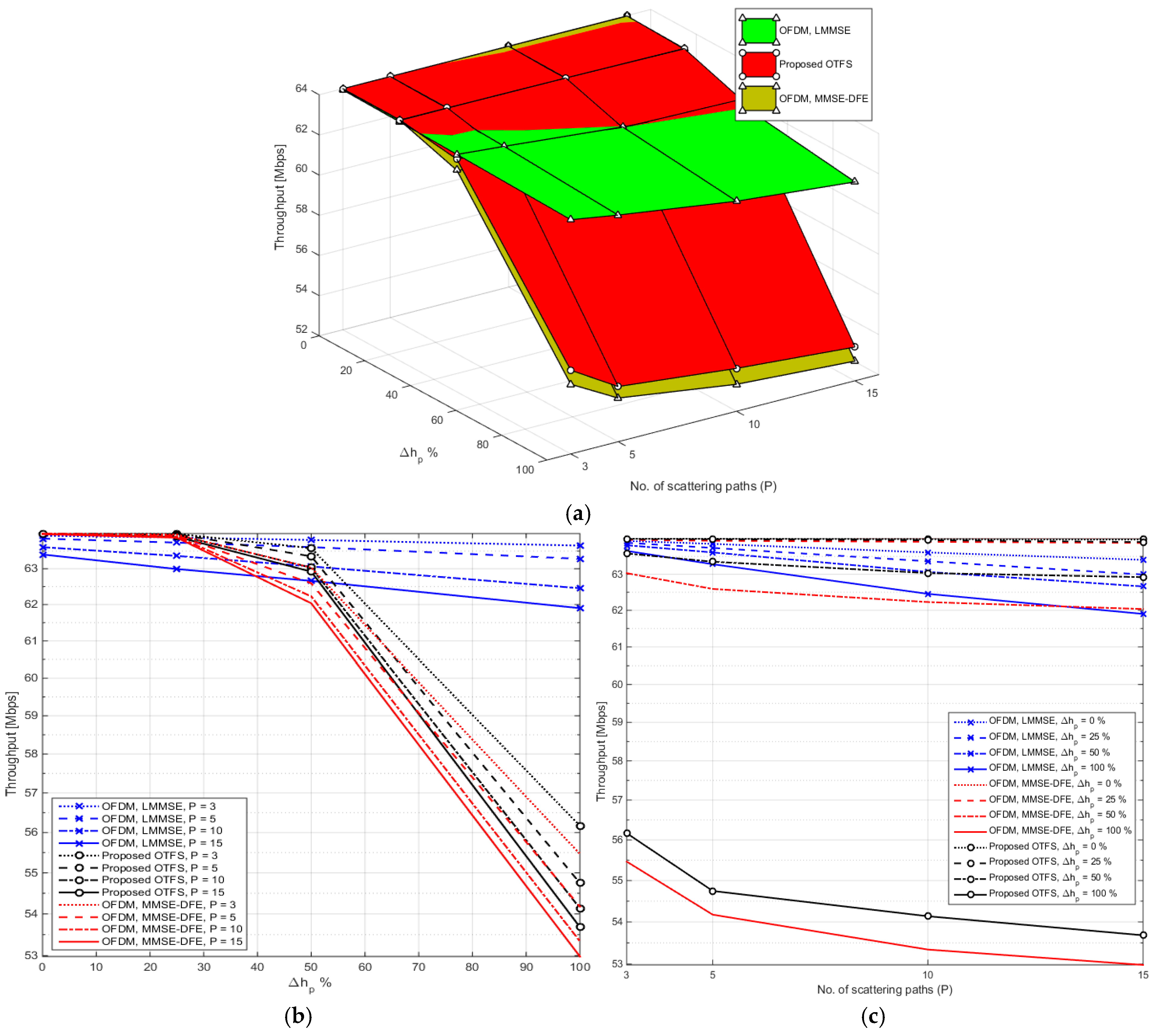
Figure 10a presents a comprehensive 3D analysis of system throughput performance as a function of both the channel estimation error percentage and the number of scattered paths at a fixed SNR of 20 dB, for the proposed OTFS and two OFDM systems: one using LMMSE equalization and the other using MMSE-DFE. Figure 10b illustrates the elevation view of Figure 10a, and Figure 10c depicts the side view of Figure 10a. The elevation view (Figure 10b) focuses on how the throughput changes with channel estimation errors. Here, the difference in stability becomes even more pronounced. OFDM-LMMSE demonstrates only a slight, almost linear decrease in throughput as error increases from 0% to 100%, regardless of the path count. In contrast, the proposed OTFS and MMSE-DFE curves slope downward more steeply, particularly at higher estimation errors, indicating their greater dependence on accurate channel knowledge.
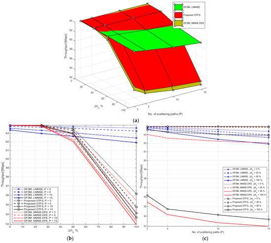
Figure 10.
(a) 3D plot of throughput vs. channel estimation error percentage and number of scattered paths for proposed OTFS and OFDM at SNR = 20 dB. (b) Elevation view of (a). (c) Side view of (a).
The side view (Figure 10c) emphasizes the effect of the number of scattered paths on throughput. As increases, the proposed OTFS system begins to exhibit a sharper decline, especially when coupled with high estimation error. OFDM-LMMSE again stands out by showing very modest throughput degradation across increasing multipath conditions, making it a more dependable solution for real-world channels with varying delay spread or Doppler spread.
Table 7 provides a numerical counterpart to the visual insights of Figure 10 by reporting the throughput (in Mbps) for the proposed OTFS and the OFDM systems across different values of (3, 5, 10, 15) and four levels of channel estimation error (0%, 25%, 50%, 100%). At = 3, the proposed OTFS and OFDM-MMSE-DFE both achieve the maximum throughput of 64 Mbps under perfect estimation. Even at 25% error, throughput drops are minimal (e.g., 63.99 Mbps for OTFS and 63.97 Mbps for MMSE-DFE). However, at 100% error, proposed OTFS drops to 56.17 Mbps, while MMSE-DFE drops to 55.47 Mbps. In contrast, OFDM with LMMSE shows superior stability, falling only slightly from 63.94 to 63.66 Mbps. This highlights LMMSE’s low sensitivity to estimation error, even with few paths. As increases to 5, the trend becomes clearer. The proposed OTFS throughput under perfect estimation remains ideal (64 Mbps), but the gap at high estimation error widens (54.75 Mbps at 100% error). OFDM-MMSE-DFE also shows signs of resilience here (62.59 Mbps at 100%), but it is the LMMSE system that remains most consistent, declining only to 63.28 Mbps under worst-case conditions. This further confirms that OFDM-LMMSE tolerates both increased multipath and poor estimation better than the other systems. At = 10, the disparity increases. The proposed OTFS drops to 54.14 Mbps under 100% estimation error, while MMSE-DFE falls to 53.34 Mbps. LMMSE again outperforms both, retaining 62.45 Mbps, demonstrating an ability to maintain usable data rates even when both estimation and channel complexity degrade. By the time reaches 15, representing a highly scattered and complex channel environment, the throughput of the proposed OTFS system has dropped to 53.68 Mbps under full estimation error, while OFDM-MMSE-DFE further falls to 52.98 Mbps. Meanwhile, OFDM-LMMSE still provides 61.90 Mbps, showing remarkable robustness and the smallest variation in performance across all error levels and path counts.

Table 7.
Throughput vs. channel estimation error percentage for different numbers of scattered paths in proposed OTFS and OFDM systems.
5. Conclusions
This study evaluates the suitability of a proposed OTFS-based system for ISAC in doubly dispersive channels, where both time and frequency selectivity pose challenges to reliable transmission and sensing. The proposed OTFS system, which operates in the delay-Doppler domain, is inherently designed to address the dynamics of such channels and is thus well aligned with the requirements of future 6G ISAC networks. Comparative analysis with OFDM employing MMSE-DFE reveals the strengths and trade-offs of each approach. Under ideal conditions with accurate channel estimation, the proposed OTFS outperforms OFDM-MMSE-DFE, achieving BER values an order of magnitude lower (e.g., 9.38 × 10⁻⁶ vs. at 20 dB SNR and 0% channel estimation error) and sustaining 64 Mbps throughput. However, as channel estimation error increases to 100% and the number of multipath scattered components rises to 15, the proposed OTFS experiences a performance decline, BER rises to 0.161, and throughput reduces to 53.68 Mbps. OFDM-MMSE-DFE also suffers under these conditions, with BER increasing to 0.172 and throughput falling to 52.98 Mbps, but its degradation is generally steeper than OTFS’s at moderate levels of estimation error. The results confirm that the OTFS waveform is more resilient to the effects of Doppler spread, making it well-suited for ISAC in high-mobility or radar-sensing scenarios. Its performance, however, is more sensitive to channel estimation accuracy, particularly in environments with a high degree of delay dispersion. On the other hand, OFDM with MMSE-DFE, while simpler to implement and effective in static or mildly time-varying channels, struggles to maintain performance in fast-fading, highly dispersive environments.
6. Future Work
To build on the promising results of the proposed OTFS-based ISAC system over doubly dispersive channels, several avenues for future research are suggested:
- Adaptive Equalization for High-Mobility ISAC Systems: Developing adaptive linear or hybrid equalization schemes to dynamically track channel variations in environments with severe Doppler and delay spreads. This will further enhance OTFS performance under rapidly time-varying conditions and improve its applicability in real-world high-mobility ISAC applications.
- Joint Waveform and Pilot Optimization: Investigating optimization strategies for pilot design, resource allocation, and waveform shaping to simultaneously improve channel estimation accuracy and sensing capability. This joint optimization is expected to enhance reliability and overall ISAC efficiency while minimizing signaling overhead.
- Future research can extend the proposed ISAC-enabled OTFS system by incorporating advanced channel estimation algorithms such as Least Squares (LS), Structured LS (SLS), and Maximum Likelihood (ML). Integrating these estimation schemes with the LMMSE-DFE equalizer may further strengthen the system’s robustness to channel uncertainty and Doppler variations in high-mobility environments.
- Additionally, future work will consider sensing-oriented performance metrics focusing on detection accuracy, such as probability of detection, probability of false alarm, and ROC curve analysis. Incorporating empirical estimation-based sensing modules will enable a more comprehensive evaluation of the ISAC performance under realistic conditions.
Author Contributions
Conceptualization, K.R., I.A. and E.S.H.; Methodology, K.R. and E.S.H.; Software, K.R., I.A. and E.S.H.; Validation, K.R., I.A. and E.S.H.; Formal analysis, K.R., I.A. and E.S.H.; Investigation, K.R. and E.S.H.; Resources, K.R. and E.S.H.; Data curation, K.R. and E.S.H.; Writing—original draft, K.R., I.A. and E.S.H.; Writing—review & editing, K.R. and E.S.H.; Visualization, K.R. and E.S.H.; Supervision, E.S.H.; Project administration, K.R., I.A. and E.S.H.; Funding acquisition, I.A. and E.S.H. All authors equally contributed. All authors have read and agreed to the published version of the manuscript.
Funding
This research work was funded by the Deanship of Graduate Studies and Scientific Research, Jazan University, Saudi Arabia, through Project number: JU-202504344-DGSSR-RP-2025.
Data Availability Statement
The original contributions presented in this study are included in the article. Further inquiries can be directed to the corresponding authors.
Conflicts of Interest
The authors declare no conflicts of interest.
Abbreviations
The following abbreviations are used in this manuscript:
| OTFS | Orthogonal Time Frequency Space |
| ISAC | Integrated Sensing and Communications |
| OFDM | Orthogonal Frequency Division Multiplexing |
| LMMSE | Linear Minimum Mean Square Error |
| DFE | Decision Feedback Equalizer |
| BER | Bit Error Rate |
| SNR | Signal-to-Noise Ratio |
| ISI | Inter-Symbol Interference |
| ICI | Inter-Carrier Interference |
| CP | Cyclic Prefix |
| LZF | Linear Zero Forcing |
| ISFFT | Inverse Symplectic Finite Fourier Transform |
| DFT | Discrete Fourier Transform |
| LTV | Linear Time-Varying |
| FFT | Fast Fourier Transform |
| SFFT | Symplectic Finite Fourier Transform |
| CCM | Composite Channel Matrix |
| BMA | Banded Matrix Approximation |
| LS | Least Squares |
| ML | Maximum Likelihood |
References
- Zhu, X.; Liu, J.; Lu, L.; Zhang, T.; Qiu, T.; Wang, C.; Liu, Y. Enabling Intelligent Connectivity: A Survey of Secure ISAC in 6G Networks. IEEE Commun. Surv. Tutor. 2024, 27, 748–781. [Google Scholar] [CrossRef]
- Zhong, Y.; Bi, T.; Wang, J.; Zeng, J.; Huang, Y.; Jiang, T.; Wu, Q.; Wu, S. Empowering the V2X network by integrated sensing and communications: Background, design, advances, and opportunities. IEEE Netw. 2022, 36, 54–60. [Google Scholar] [CrossRef]
- Wang, T.; Proakis, J.; Masry, E.; Zeidler, J. Performance degradation of OFDM systems due to doppler spreading. IEEE Trans. Wirel. Commun. 2006, 5, 1422–1432. [Google Scholar] [CrossRef]
- Ramadan, K. Performance improvement of MIMO–OFDM communication systems based on non-linear equalization. Comput. Electr. Eng. 2025, 124, 110287. [Google Scholar] [CrossRef]
- Ramadan, K. Improved DWT-OFDM system performance with wavelet domain equalization for Co-CFO mitigation. Telecommun. Syst. 2025, 88, 93. [Google Scholar] [CrossRef]
- Ramadan, K.; Hassan, E.S. Linear WDE for Performance Enhancement of MIMO-OFDM System in the Presence of Co-CFO. Def. Technol. 2025, 51, 51–66. [Google Scholar] [CrossRef]
- Lin, J.; Chen, Q.; Hua, Y.; Chen, C. Joint Optimization and Performance Analysis of Analog Shannon–Kotel’nikov Mapping for OFDM with Carrier Frequency Offset. Entropy 2025, 27, 778. [Google Scholar] [CrossRef]
- Keskin, M.F.; Marcus, C.; Eriksson, O.; Alvarado, A.; Widmer, J.; Wymeersch, H. Integrated Sensing and Communications with MIMO-OTFS: ISI/ICI Exploitation and Delay-Doppler Multiplexing. IEEE Trans. Wirel. Commun. 2014, 23, 10229–10246. [Google Scholar] [CrossRef]
- Sun, Y.; Shambare, C.; Imoru, O. OFDM Network Optimization Using a QPSK Based on a Wind-Driven Genetic Algorithm. Sensors 2022, 22, 6174. [Google Scholar] [CrossRef]
- Ramadan, K.; Dessouky, M.I.; El-Samie, F.E.A. Performance enhancement of OFDM systems with lower-complexity using DST based on successive interference cancellation. Digit. Signal Process. 2020, 102, 102739. [Google Scholar] [CrossRef]
- Srinivasulu, O.; Kumar, P.R. Analysis of Multiple Input Multiple Output-Orthogonal Frequency Division Multiplexing with Dynamic Optimal Power Allocation. Eng. Technol. Appl. Sci. Res. 2024, 14, 15515–15521. [Google Scholar] [CrossRef]
- Ababneh, J.; Attar, H.; Muda, Z.C.; Colak, I.; Deif, M.A.; Bendoukha, S.; Solyman, A. Enhanced nonlinear equalization for OFDM systems in IoT-based intelligent transportation using CGLS algorithms. J. Wirel. Com. Netw. 2025, 2025, 61. [Google Scholar] [CrossRef]
- Kulhandjian, M.; Kulhandjian, H.; Kurt, G.K.; Yanikomeroglu, H. Delay-Doppler Domain Pulse Design for OTFS-NOMA. In Proceedings of the 2024 IEEE International Conference on Communications Workshops (ICC Workshops), Denver, CO, USA, 3–19 June 2024. [Google Scholar]
- Rou, H.S.; de Abreu, G.T.F.; Choi, J.; González, D.G.; Kountouris, M.; Guan, Y.L.; Gonsa, O. From Orthogonal Time–Frequency Space to Affine Frequency-Division Multiplexing: A comparative study of next-generation waveforms for integrated sensing and communications in doubly dispersive channels. IEEE Signal Process. Mag. 2024, 41, 71–86. [Google Scholar] [CrossRef]
- Wei, Z.; Yuan, W.; Li, S.; Yuan, J.; Bharatula, G.; Hadani, R.; Hanzo, L. Orthogonal time-frequency space modulation: A promising next-generation waveform. IEEE Wirel. Commun. 2021, 28, 136–144. [Google Scholar] [CrossRef]
- Zeng, R.; Lin, Z.; Zhang, Z.; Ying, N.; Yang, A. Spectrum Efficiency and Link Reliability Enhancement Algorithm in IRS-Assisted OTFS Systems for Vehicular Networks. IEEE Commun. Lett. 2025, 29, 1924–1927. [Google Scholar] [CrossRef]
- Wang, C.; Wang, Y.; Zheng, H.; Chai, Y.; Dong, Y. Dong Precision Sensing-Aided Multi-Target Beamforming Prediction in High-Mobility ISAC Systems Based on OTFS. IEEE Access 2025, 13, 16623–16636. [Google Scholar] [CrossRef]
- Wu, N.; Jiang, R.; Wang, X.; Yang, L.; Zhang, K.; Yi, W.; Nallanathan, A. AI-Enhanced Integrated Sensing and Communications: Advancements, Challenges, and Prospects. IEEE Commun. Mag. 2024, 62, 144–150. [Google Scholar] [CrossRef]
- Wen, D.; Zhou, Y.; Li, X.; Shi, Y.; Huang, K.; Letaief, K.B. A Survey on Integrated Sensing, Communication, and Computation. IEEE Commun. Surv. Tutor. 2025, 27, 3058–3098. [Google Scholar] [CrossRef]
- Cui, Y.; Ding, H.; Ma, Y.; Li, X.; Zhang, H.; Fang, Y. Energy-Efficient Integrated Sensing and Communication in Collaborative Millimeter Wave Networks. IEEE Trans. Wirel. Commun. 2025, 24, 2341–2357. [Google Scholar] [CrossRef]
- Jia, C.; Zhao, Z.; Sun, L.; Quek, T.Q.S. An Interference Cancelation Scheme of Integrated Sensing and Communications in Wireless Networks. IEEE Wirel. Commun. Lett. 2024, 13, 3429–3433. [Google Scholar] [CrossRef]
- González-Prelcic, N.; Keskin, M.F.; Kaltiokallio, O.; Valkama, M.; Dardari, D.; Shen, X.; Shen, Y.; Bayraktar, M.; Wymeersch, H. The Integrated Sensing and Communication Revolution for 6G: Vision, Techniques, and Applications. Proc. IEEE 2024, 112, 676–723. [Google Scholar] [CrossRef]
- Xie, C.; Li, Y.; Chen, L.; Shi, W.; Zhang, Z.; Xiu, Y. Power Minimization for Integrated Sensing, Communication, and Power Transmission Systems. IEEE Commun. Lett. 2024, 28, 2779–2783. [Google Scholar] [CrossRef]
- Singh, S.; Samal, U. Integrated Sensing and Communication in Next-Generation Wireless Networks: Insights and Trends. Int. J. Commun. Syst. 2025, 38, e70014. [Google Scholar] [CrossRef]
- Demirhan, U.; Alkhateeb, A. Cell-Free ISAC MIMO Systems: Joint Sensing and Communication Beamforming. IEEE Trans. Commun. 2025, 73, 4454–4468. [Google Scholar] [CrossRef]
- Liu, Y.; Huang, T.; Liu, F.; Ma, D.; Huangfu, W.; Eldar, Y.C. Next-Generation Multiple Access for Integrated Sensing and Communications. Proc. IEEE 2024, 112, 1467–1496. [Google Scholar] [CrossRef]
- Zhang, J.A.; Rahman, L.; Wu, K.; Huang, X.; Guo, Y.J.; Chen, S.; Yuan, J. Enabling joint communication and radar sensing in mobile networks—A survey. IEEE Commun. Surv. Tuts. 2022, 24, 306–345. [Google Scholar] [CrossRef]
- Zhang, S.-Y.; Zhang, Y.-X.; Shahrrava, B. Orthogonal Time Frequency Space with Sub-Band Index Modulation. IEEE Commun. Lett. 2025, 29, 1047–1051. [Google Scholar] [CrossRef]
- Sheikh-Hosseini, M.; Rahdari, F.; Ghasemnezhad, H.; Ahmadi, S.; Uysal, M. A Comparative Performance Evaluation of OFDM, GFDM, and OTFS in Impulsive Noise Channels. IEEE Open J. Commun. Soc. 2025, 6, 2693–2705. [Google Scholar] [CrossRef]
- Li, B.; Yuan, W.; Liu, F.; Wu, N.; Jin, S. OTFS-Based ISAC: How Delay Doppler Channel Estimation Assists Environment Sensing? IEEE Wirel. Commun. Lett. 2024, 13, 3563–3567. [Google Scholar] [CrossRef]
- Singh, P.; Gupta, A.; Mishra, H.B.; Budhiraja, R. Low-Complexity ZF/MMSE MIMO-OTFS Receivers for High-Speed Vehicular Communication. IEEE Open J. Commun. Soc. 2022, 3, 209–227. [Google Scholar] [CrossRef]
- Cao, Z.; Tureli, U.; Yao, Y.-D. Low-complexity orthogonal spectral signal construction for generalized OFDMA uplink with frequency synchronization errors. IEEE Trans. Veh. Technol. 2007, 56, 1143–1154. [Google Scholar] [CrossRef]
Disclaimer/Publisher’s Note: The statements, opinions and data contained in all publications are solely those of the individual author(s) and contributor(s) and not of MDPI and/or the editor(s). MDPI and/or the editor(s) disclaim responsibility for any injury to people or property resulting from any ideas, methods, instructions or products referred to in the content. |
© 2025 by the authors. Licensee MDPI, Basel, Switzerland. This article is an open access article distributed under the terms and conditions of the Creative Commons Attribution (CC BY) license (https://creativecommons.org/licenses/by/4.0/).

