1. Introduction
Piecewise-smooth (PWS) systems have become of interest in recent decades for their dynamics associated with a wide range of applications in engineering, economics, biology, physics, and other fields. There are numerous practical systems that are governed by the dynamics of piecewise smooth systems. Some of them are DC motor drives, switching circuits, power systems [
1,
2,
3,
4,
5,
6], pulses width modulators [
7,
8], Tantalus and impact oscillators [
9,
10], hybrid systems, and in financial markets [
11,
12,
13,
14]. The interest in piecewise smooth systems is due to a special bifurcation phenomenon that occurs only in non-smooth dynamical systems. This is termed the border collision bifurcation (BCB) [
15] and was first reported by M. Feigin [
16]. There is a large body of work on smooth systems [
17,
18,
19]. For more than a decade, the focus has been on piecewise smooth discontinuous maps. The results for one-dimensional maps [
20,
21,
22], two-dimensional maps [
4,
23], three-dimensional maps [
24,
25], n-dimensional maps [
26], linear discontinuous maps as well as co-dimension maps [
27,
28] have been reported by various authors.
The PWS discontinuous maps must be analyzed, as there is a wide range of phenomena that can occur; some are stable and unstable periodic orbits, which are admissible or non-admissible and converge to unstable periodic or leading to chaotic orbits [
29]. Furthermore, atypical orbits are discussed in [
30]. The stable periodic orbits are structured in a particular manner in 1
D piecewise smooth discontinuous maps which constitute period adding cascades [
31]. BCB curves are analyzed numerically, analytically, or by simplified method, i.e., a map replacement technique proposed by Leonav [
32,
33,
34]. The approach is then simplified and extended to discuss the analytical results and characterization of stable [
20], unstable [
21], and periodic orbits of the 1
D map. This work is helpful in knowing the exact number of distinct periodic orbits at a given cardinality. In the previous work, slopes in the map were assumed to be positive and respective results are proven.
In power electronics, non-smooth maps are particularly relevant for analyzing switched-mode converters (viz. buck, boost, and hybrid inverters) that operate with discontinuous control laws, such as pulse-width modulation (PWM) or hysteresis-based switching [
35,
36,
37]. For instance, the dynamics of grid-tied inverters under maximum power point tracking (MPPT) are often demonstrated as linear piecewise-smooth discontinuous (LPSD) maps due to abrupt transitions between operating modes [
38,
39]. Recent studies have leveraged PWS theory to predict chaotic oscillations and stabilize DC–DC converters in photovoltaic (PV) systems, while demonstrating its utility in mitigating subharmonic instabilities in wind energy inverters [
40,
41,
42]. Although significant progress has been made in the theoretical and applied analysis of PWS maps, a critical gap remains in leveraging this framework for the sustainable design of power converters, particularly in regimes characterized by negative slopes, which are commonly encountered in applications such as bidirectional power flow in battery-integrated systems. The existing body of work predominantly addresses positive-slope dynamics, while the nonlinear behavior of negative-slope LPSD maps remains comparatively underexplored, despite their relevance in systems involving regenerative braking and grid-following inverters. Furthermore, analytical tools for the rapid stability assessment of such maps under disturbances remain limited. Atypical orbit types—such as continuum period-2 solutions—are not well characterized.
In the design of power electronic converters, system parameters—such as input voltage, inductor, or capacitor value, and load range—are typically selected to ensure stable operation and avoid undesirable behaviors like sub-harmonic oscillations or chaotic dynamics. However, determining the exact regions in the parameter space where these nonlinear phenomena emerge remains a challenge. Such regions are often identified through empirical methods, including laboratory experiments or detailed time-domain simulations. Bifurcation theory offers a systematic and analytical framework for addressing this issue by elaborating the boundaries of stable periodic operation, particularly the period-1 regime. This is achieved by constructing a discontinuous map, which involves sampling the system state at discrete intervals synchronized with the switching clock. The stability of period-1 orbit is maintained as long as the eigenvalues of the associated return map lie within the unit circle in the complex plane. This paper presents a PWS map resembling the mathematical model of non-smooth systems. In this paper, we carry out a detailed analysis of stable and unstable periodic orbits that can appear in 1D piecewise smooth discontinuous maps when slopes in the map are negative, by focusing on phenomena which are new and interesting. The main objective of the paper is to give assertive mathematical insights into the 1D PWS map, which has not been done previously. Furthermore, the proposed approach will help in designing the sustainable power converters that can operate under the dynamic conditions.
This paper is organized as follows. In
Section 2, one-dimensional map definition and related terms are provided.
Section 3 reviews region
P, and the results are discussed. Also, some typical phenomena for particular parameter boundary values (
) are considered in
Section 4, which have not been discussed earlier in the analysis using numerical simulations. Furthermore,
Section 5,
Section 6,
Section 7 and
Section 8 discuss the results and analyses of other boundary line and unstable region cases. The analyzed work is summarized in
Section 9.
2. Definition of the 1- Map
The 1-
D linear piecewise-smooth discontinuous map is [
29]:
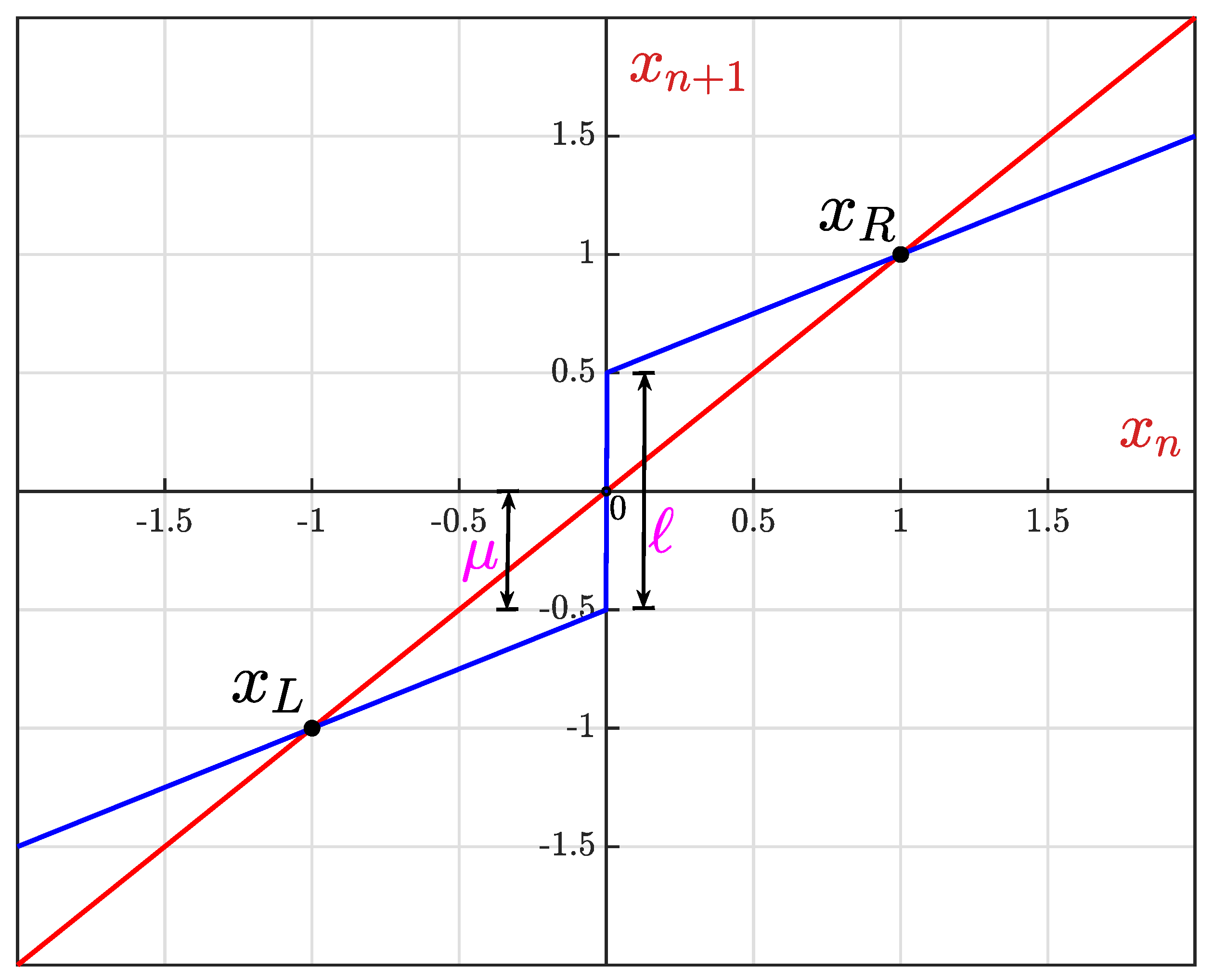
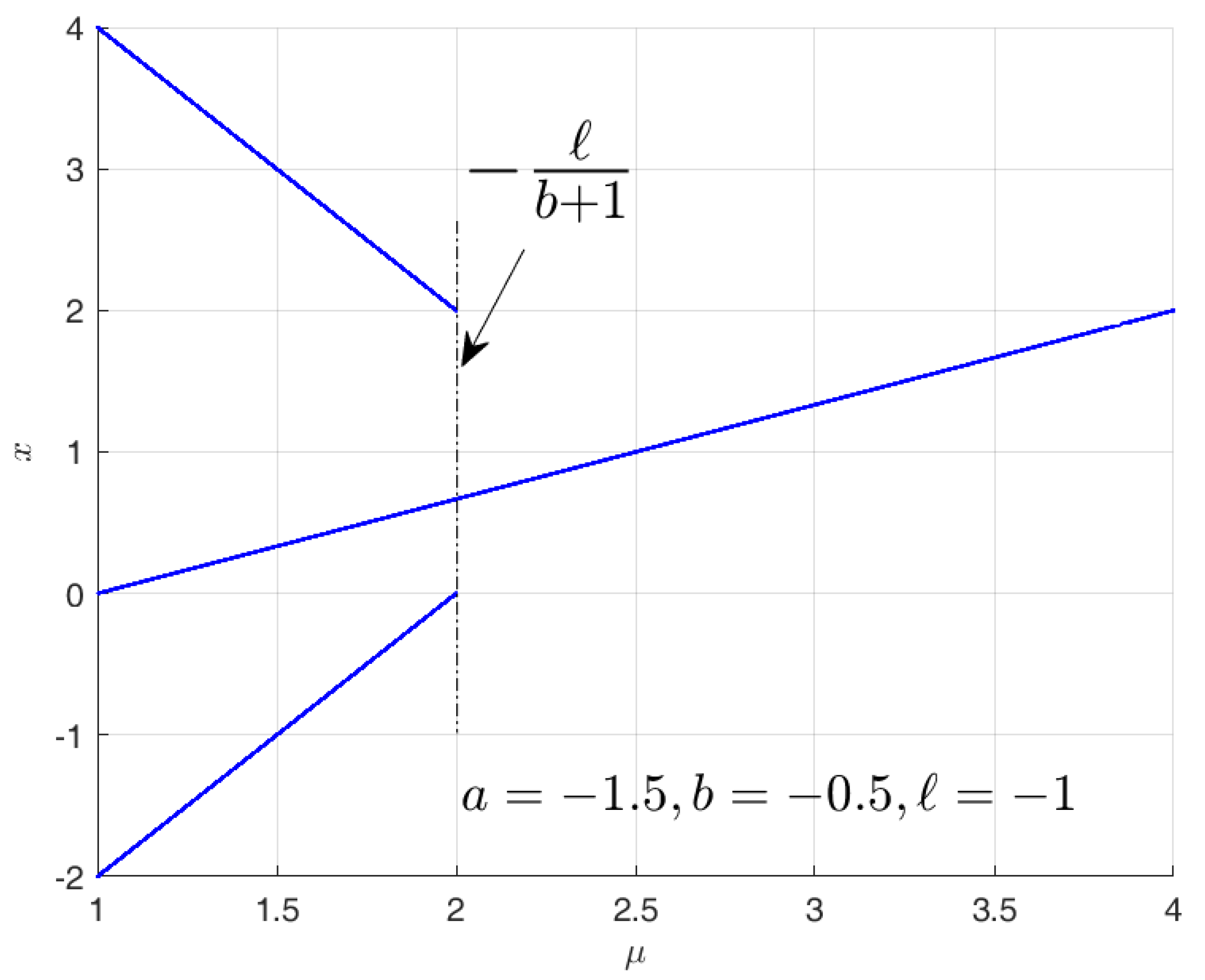
Figure 1 illustrates the map (
1), with
,
and
.
Here, ‘
a’, ‘
b’ and ‘
’ are parameters, whlie jump discontinuity is denoted by ‘
ℓ’. The map has
(the closed left half plane) and
(the open right half plane). Given a particular sequence of points
through which the system evolves, one can convert this into a sequence of
and
by indicating which of the two sets (
or
) the each point belongs to. Clearly, a periodic orbit corresponds to a string
and
that repeats indefinitely. We call this repeating string, a
pattern, and denote it by
. The length of the string
is denoted by
and gives the number of symbols in the pattern, i.e., the period of the orbit.
denotes the interval of the parameter
for which pattern
exists. We denote the sum of geometric series
by
. The basic notions of 1-
D PWS map are discussed in the literature [
20,
43].
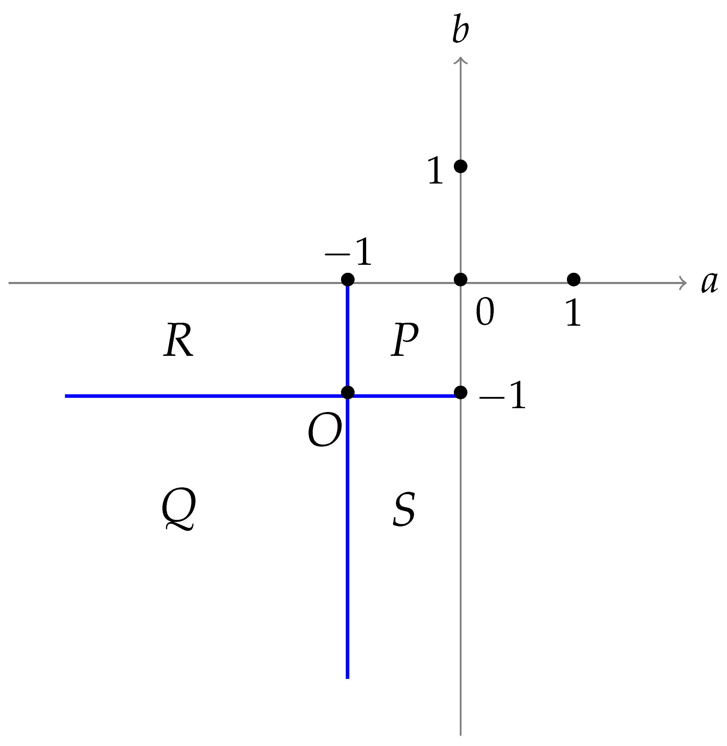
The parameters ‘
a’ and ‘
b’ can take either positive or negative values, and they divide the
-plane into four quadrants, as depicted in
Figure 2 and characterized in [
22]. Stable–unstable periodic orbits and chaotic orbits are discussed in detail for quadrants for which
a and
b are both positive values [
20,
21]. Results based on different parameter values are illustrated in [
44], where it is shown that the dynamics of the attractor and Poincaré rotation on the unit circle behave alike. Furthermore, conditions on the parameters are obtained that exhibit the topological attractor. In this work, we make an attempt to investigate all possible orbits and characterize the map for the quadrant in which both parameters have negative values. The quadrant III is again subdivided into four regions and three boundary cases, based on values of
a and
b as follows. For region
P,
, region
Q takes
. Previous work has shown that regions
R and
S are equivalent, where one parameter belongs to
and the other is less than
and vice versa. The boundaries
,
and boundary point
are analyzed in this work.
4. Boundary Point
This is a very special case, as it is the boundary point for all regions and lines.
In this case, and three scenarios are observed for each with and .
4.1. Scenario :
For
, from the map it is clear that there exists a stable fixed point in the right-half plane. The location of the fixed point can be obtained from map (
1) as
It is a stable attractor, only for points
, where
is a whole number, and the remaining points form orbits of period-2 of type
.
4.2. Scenario :
For , one stable fixed point in the left half-plane given by is present and is a stable attractor, only for points . All other initial points form period-2 orbits of type .
4.3. Scenario :
For
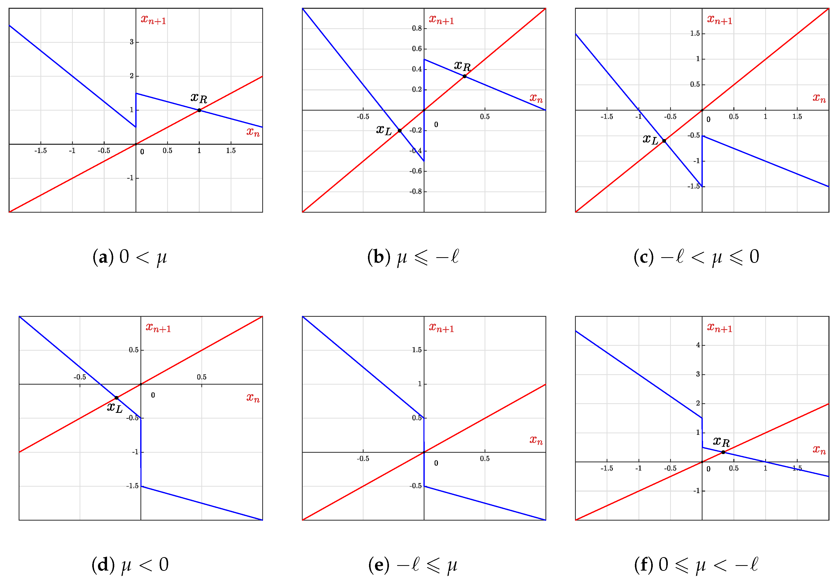
, there exist two stable fixed points on either side of the discontinuity, as shown in
Figure 9. Fixed points
and
are stable attractor only for points
and
, respectively.
4.4. Scenario :
For , there exists a stable fixed point and points , form period-2 orbit. All other points move away and form unstable orbits.
4.5. Scenario :
For , there are no fixed points, and any initial point diverges to .
4.6. Scenario :
For , there exists a stable fixed point and points in form periodic orbit, and all other points except for this range lead to instability.
4.7. Analysis
4.7.1.
Proposition 1. The boundary point O with a positive length of discontinuity; only orbits are admissible when .
Proof. With both positive, there exists a fixed point in given by , for , .
Since the magnitudes of slopes of a and b are equal to 1, any keeps oscillating around the . A detailed analysis is given below considering all possible ranges in accordance with .
Orbits for Different Initial Conditions
Using map (
4), the following analysis is carried out,
This condition illustrates that
and
repeat alternately, forming a period-2 orbit. Furthermore, the repeating points of these
orbits are
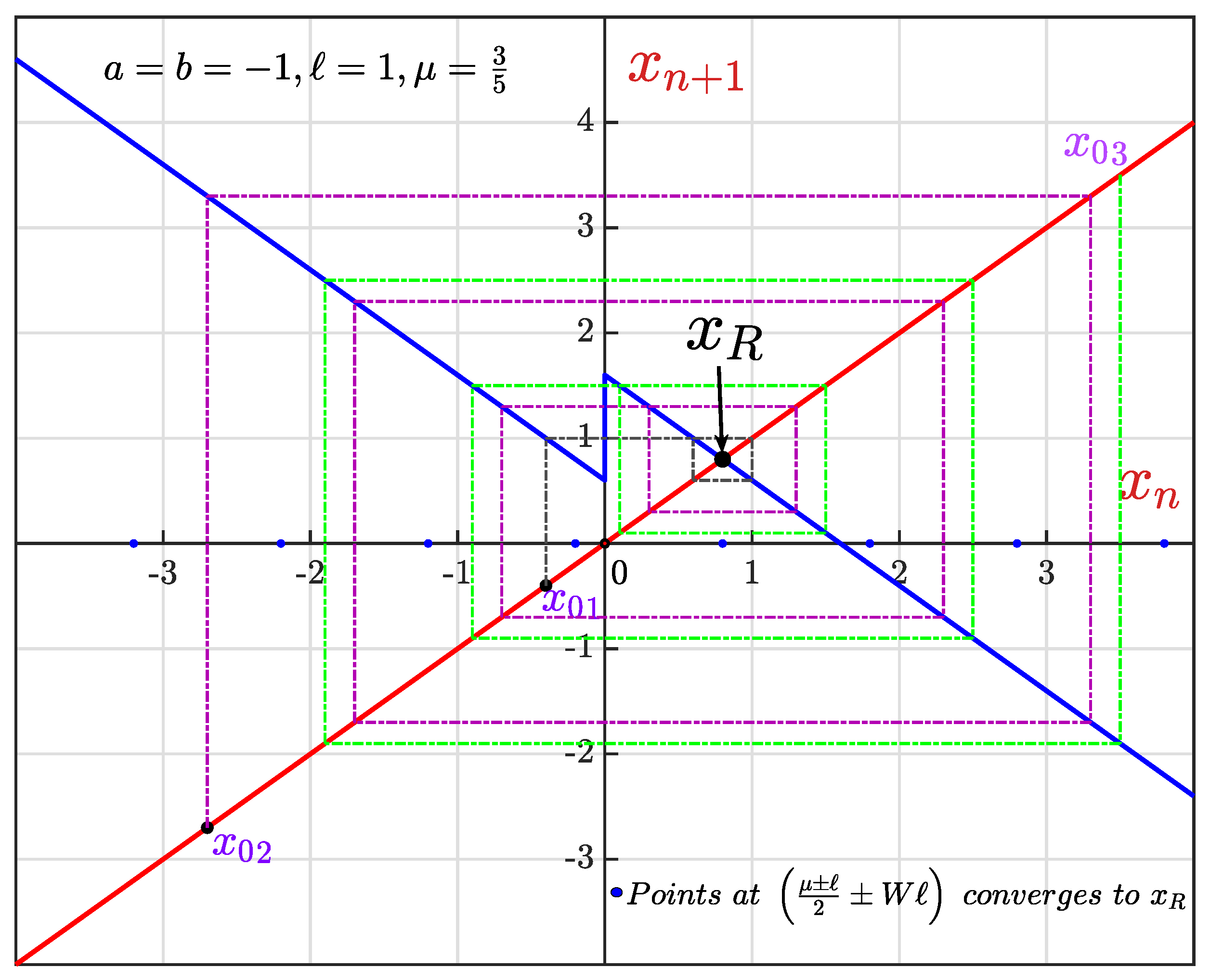
. This is illustrated in
Figure 10 with initial condition
with a black color plot and
orbit settles at points
.
This case is represented by a magenta color line in
Figure 10, where
and
, so repeating points are at
.
The green color lines shown in
Figure 10 elaborate this case, where
, then
and the period-2 orbit is formed at
.
Number of Iterations
The number of iterations or steps required to go into periodic orbit is calculated as follows, for :
Consider
, where
Here, it is a period-2 orbit of type
with fixed points at
and it takes
steps to become periodic. In the aforementioned examples
and
takes 2
nd and 6
th steps, respectively, to enter the
orbit.
Consider
, where
Thus, it is a period-2 orbit of type
with fixed points at
and it becomes periodic after
iterations. For
it becomes periodic after 4th iteration i.e., 5th iteration is in periodic orbit. □
4.7.2.
Proposition 2. In boundary point O with and , only orbits exists.
Proof. The fixed point in this scenario () is for , .
Similar to the proof of Proposition 1, any will form a period-2 orbit with both periodic points being negative, forming orbit. For different , the detailed analysis, including the number of iterations required to go into orbit, is illustrated below.
Orbits for Different Initial Conditions
Using (
4) for the following analysis,
For this condition, there will be always a period-2
orbit with fixed points at
that is in periodic orbit from the initial step. An initial condition
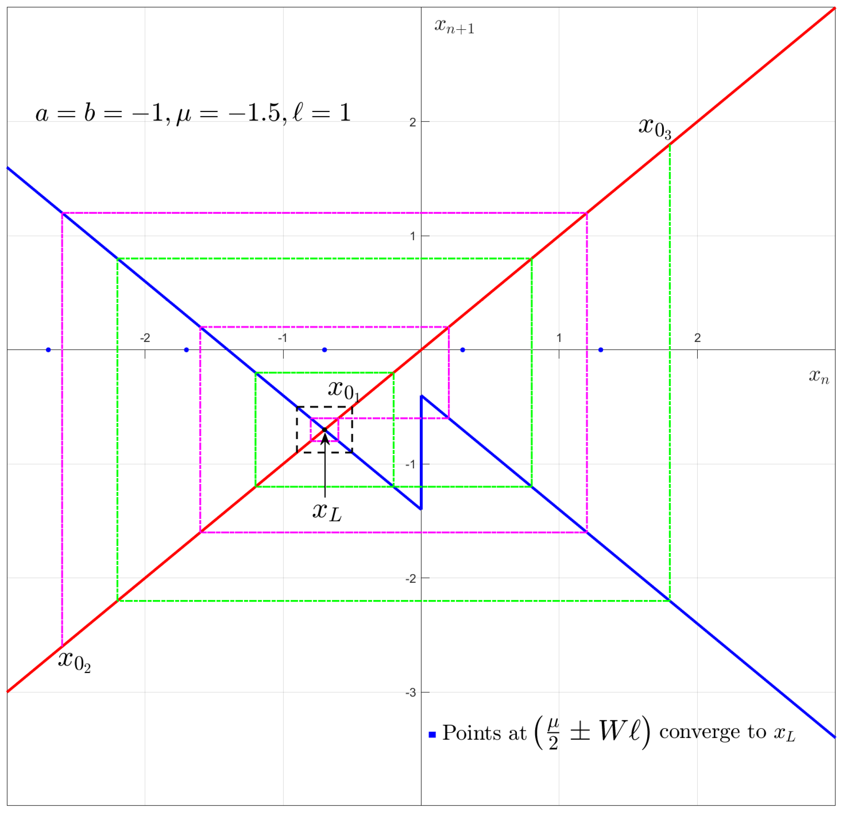
and the evolution of its path are depicted in
Figure 11 with a black color plot.
So on, with periodic orbit
, and fixed points are at
. This scenario is illustrated with an example as
and the corresponding plot is shown in the magenta color in
Figure 11.
This case is shown in
Figure 11 with a green color plot, where
.
Number of Iterations
The number of iterations or steps required to go into periodic orbit is calculated as follows for :
Consider,
, where
Thus, there is a period-2
orbit with fixed points at
; after
iterations it becomes periodic. Applying this to
and
, the map dynamics goes into periodicity after 0th and 4th iterations, respectively.
Consider,
, where
Thus, a period-2 orbit of type
exists with fixed points at
and it becomes periodic after
iterations. For
,
, so after 3rd iteration it goes into
orbit. □
4.7.3.
Proposition 3. The boundary point O with and exhibits as well as orbits.
Proof. The map (
4) has two fixed points
with the conditions of
and
. Here, for any
based on Propositions 1 & 2, only either
or
orbits are possible and are proved in the below analysis.
Orbits and Number of Iterations
Map (
4) is used for the following analysis,
:
Consider,
, where
- 1.
Now, if , then
Thus, forming periodic orbit
with fixed points at
it becomes periodic after
steps. For example,
gives
and goes into
orbit after three iterations.
- 2.
Now, if , then
and
.
Thus, it forms a
periodic orbit with fixed points at
and it becomes periodic after
iterations. Consider that
gives
and forms
orbit after six iterations.
:
Consider
, where
- 1.
Now, if , then
Thus. there will be
periodic orbit with fixed points at
and it becomes periodic after
steps. Let
, then
, so it goes into a periodic orbit after two steps.
- 2.
Now if , then
and
.
Thus, it forms
periodic orbit with fixed points at
and it becomes periodic after
iterations. Say
, then
, so it forms
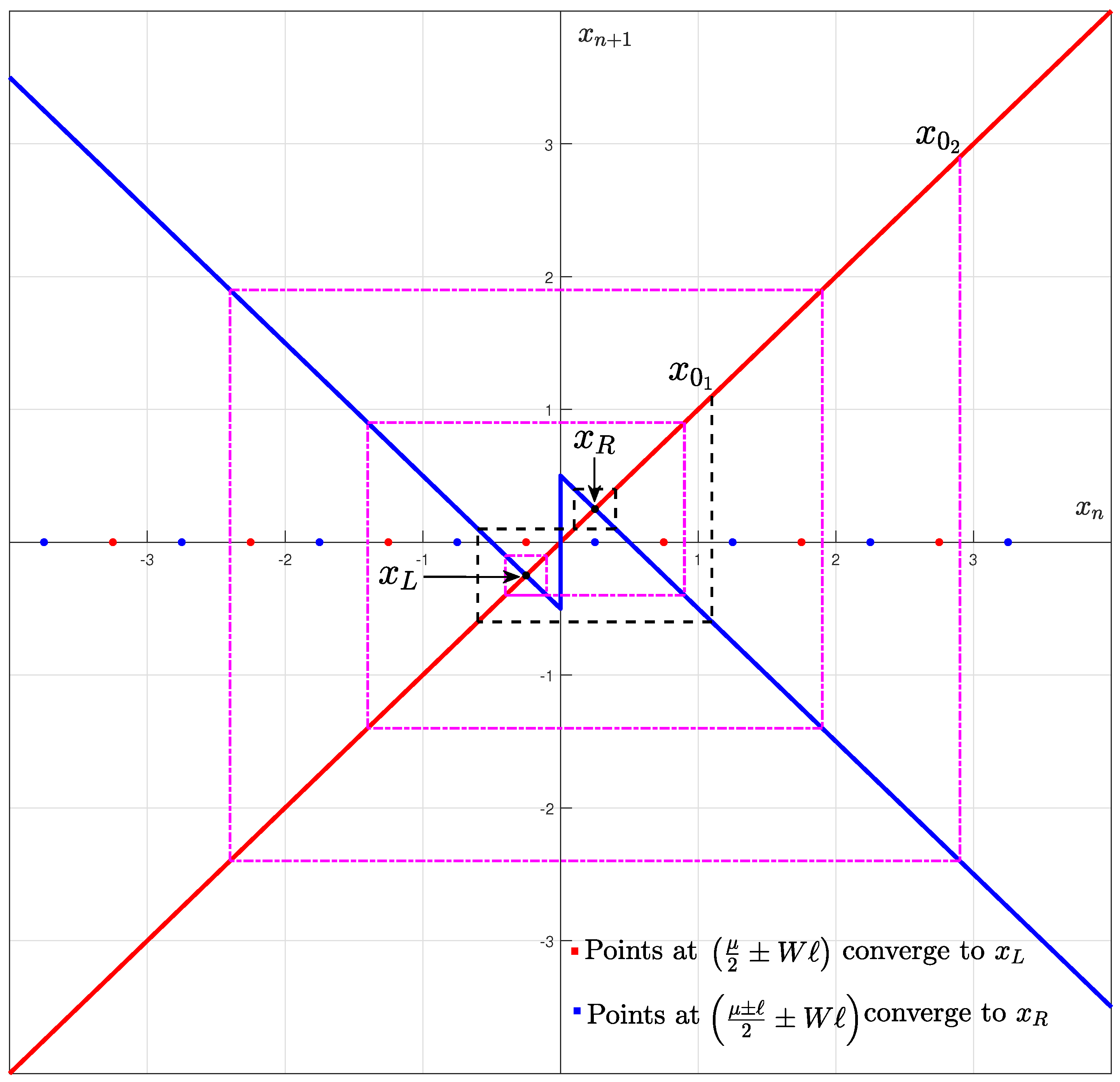
orbit after five steps. These cases are shown in the
Figure 13.
□
Lemma 3. The only admissible patterns for the boundary point O scenario with positive length of discontinuity (ℓ) are or .
Proof. The boundary point scenario has a magnitude of both slopes (
) equal to one, so for any fixed point (
), the map dynamics takes any initial point into oscillatory mode, specifically a period-2 orbit. Based on the values of parameters
, these period-2 oscillations go into
or
patterns. These period-2 orbits are neither asymptotically stable nor unstable. Hence, this scenario is equivalent to period-2, which is explained in [
30] in the boundary point
These admissible orbits are proved in Propositions 1–3 by considering all possible variations. □
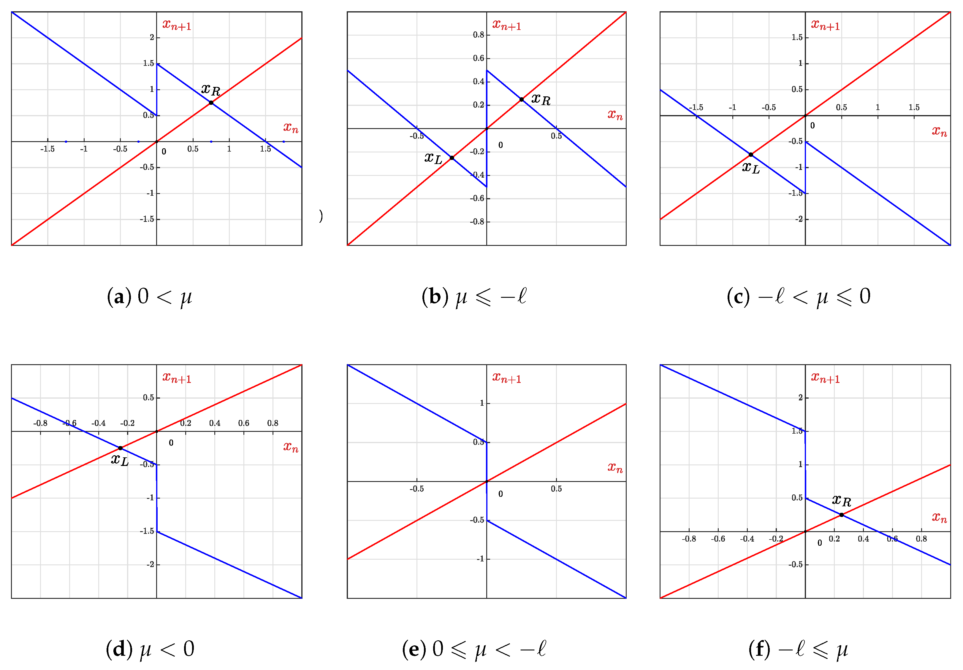
Lemma 4. Under the action of map (
4),
any initial point moves towards infinity except a certain range of initial conditions depending on μ, when . Proof. Any fixed point (
) under the action of map (
4) with
acts similarly to an unstable fixed point, as both slopes of the map go away from the fixed points. Moreover, there is no common portion of slopes during the next iterations, as can be seen in
Figure 9d–f. The detailed analysis and proof for different values of
and
are discussed below.
4.7.4.
Consider i.e.,
Thus, it forms a period-2 orbit with fixed points at and is periodic from the initial step.
Here, except all other points are unstable, and it can be shown as:
For
This
sequence continues and the points eventually move to
as
.
For
As
, the points go to
, leading to instability.
4.7.5.
Here, any forms unstable sequences and under the action of the map, any initial point moves towards infinity.
4.7.6.
Consider
Thus, it forms a periodic orbit with fixed points as and is periodic from initial iteration.
Here, except for , all other points are unstable and can be proved as above. □
5. Boundary Line :
The boundary line case observes three scenarios when
5.1. Scenario :
For , from the map it is clear that there exists a stable fixed point , which is a global attractor.
5.2. Scenario :
For , one stable fixed point in the left half plane and it is given by . Which is a global attractor forming periodic orbit-2 of type .
5.3. Scenario :
For
, since two stable fixed points, on either side of the discontinuity as shown in
Figure 14. Here, either points attract towards
or forms a periodic orbit around
. For
, following cases are seen:
5.4. Scenario :
For , there is a stable fixed point that acts as an attractor for , forming a period-2 orbit of type , all other points form a periodic orbit .
5.5. Scenario :
For , there exists one stable fixed point which is attractor for . Otherwise, there will be a periodic orbit.
5.6. Scenario :
For , there are no fixed points, and a periodic orbit is formed.
5.7. Analysis of Boundary Line
The analysis of boundary line
is carried out based on the map, where
5.7.1.
From map (
5), for
and
, it is seen that there exists a stable fixed point
in right half plane. As the magnitude of
, any point on
x will attract towards
, so it is a global attractor.
5.7.2.
In this case, and . There exists a stable fixed point and period-2 orbits around it. The fixed points for this orbit are found as follows:
. Consider,
where
So, with periodic orbit
with fixed points as
, it becomes periodic after
iterations.
. Consider
Thus, there exists a period-2 orbit of type
with points
; it becomes periodic after
steps.
5.7.3.
In this scenario, both
and
exist. All points
form period-2 orbits around
and others either form period-2 orbits or attract towards
. This can be seen in
Figure 15.
from induction, we write a range for a period-2 orbit of type
for
,
where
.
All other points except for the above range attract towards .
if
if
if
Similar to induction, we write
where
.
The points other than the above range move towards the stable fixed point .
Proposition 4. Only admissible patterns in the boundary line with positive length of discontinuity are fixed point (period-1) and period-2 () solutions.
Proof. The boundary line has , therefore, the fixed point in is going to be a stable attractor, which is seen in the above analysis when . Thus, any initial point attracts to , making it a global attractor and exhibiting a fixed point or period-1 solution. However, for , the fixed point is neither stable nor unstable due to the slope . So, any point keep oscillating around forming orbits of period-2 (). Furthermore, when , both and are present; therefore, a certain range of initial points attract towards , and the remaining points form orbits. □
5.7.4.
In this case, when then , forming the period-2 orbit of type with fixed points .
For all other points, there will be a period-2 orbit as the magnitude of slope is either 1 or less than 1.
and
. Thus, the fixed points of
orbit are:
Considering without loss of generality,
.
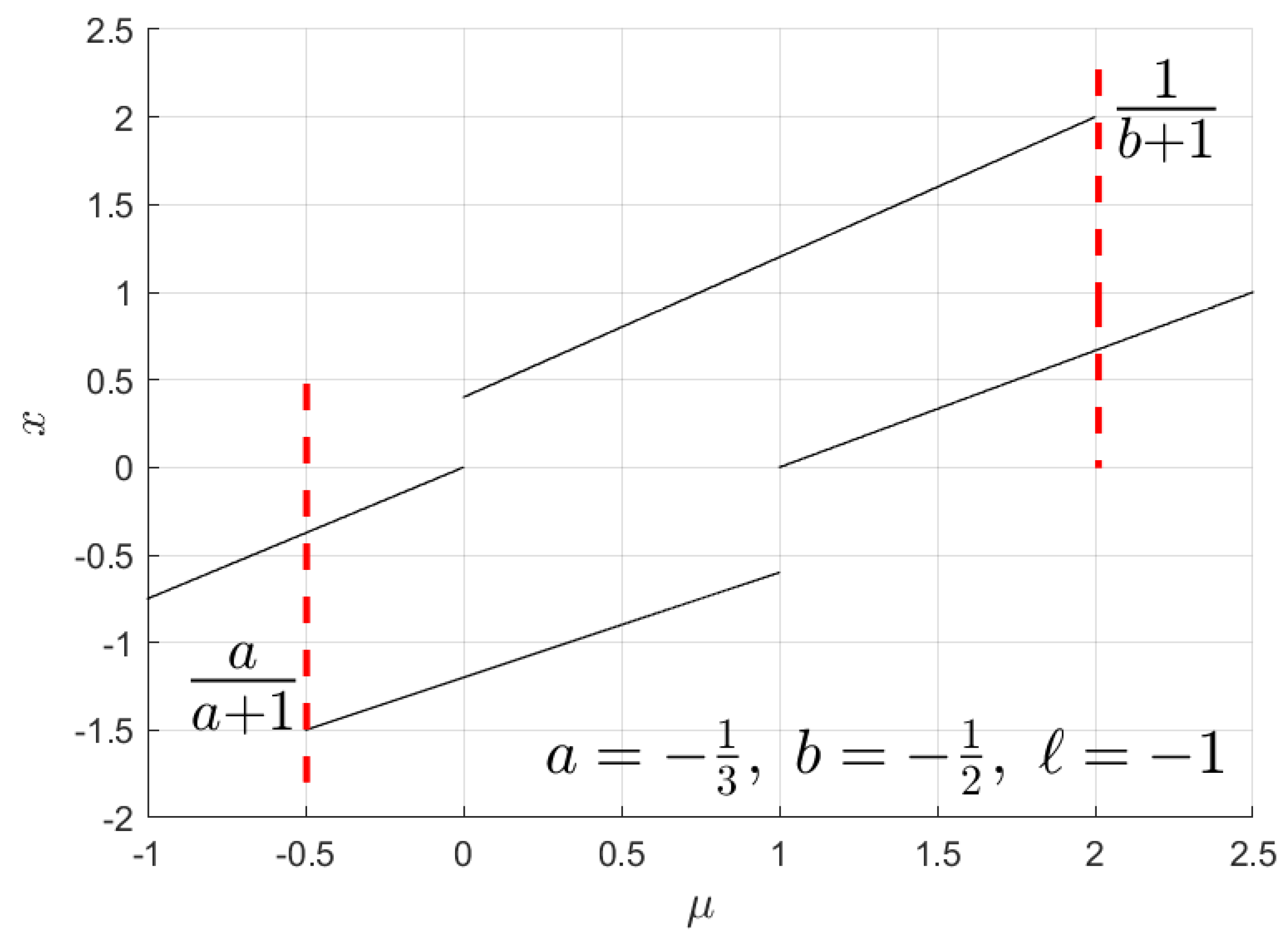
It can be observed from the bifurcation diagram in
Figure 16 that
exceeds the range for case
and enters into the range of
for cases
and
.
5.7.5.
In this scenario (
), there is a stable fixed point
. Moreover, when
, it will have either period-1 or period-2 solutions. The period-1 solution occurs only when
, and all other initial points exhibit a period-2
orbit. Furthermore, when
, then any initial point
will attract towards the fixed points
. This is evident in the bifurcation diagram shown in
Figure 16.
The
orbit periodic points are calculated as follows, when
Thus, the fixed points for
orbit are
5.7.6.
In this case, there is no fixed point on either side, and the map slope magnitudes are also , so it forms a period-2 orbit with fixed points given by (6).
Proposition 5. The line with negative ℓ exhibits fixed point and period-2 solutions.
Proof. The fixed point in makes the points to oscillate within forming orbit and all other points form period-2 () orbit, when . When , due to either a fixed point solution or orbit are admissible for different initial points. When and , there is no fixed point in or . Therefore, any initial point keeps oscillating between the left and right regions, making it a period-2 orbit. □
Lemma 5. Period-1 and period-2 ( &∖or ) are the only admissible patterns in boundary line .
Proof. The proof follows from Propositions 4 & 5. We illustrate the results of Lemma 5 in
Figure 15 and
Figure 16. □
9. Conclusions
This work presents a comprehensive analytical study of a one-dimensional linear piecewise-smooth discontinuous map with both slope parameters negative, thereby exploring the dynamical regimes situated in the third quadrant of the parameter space. The bifurcation behavior and orbit structures of the map were systematically analyzed by varying the parameters and ℓ, under the constraint that the absolute values of the slopes remain less than or equal to one. Special emphasis was placed on identifying the parameter conditions that lead to stable periodic orbits, especially period-2 and period-2 orbits of types ( or ), which emerge as characteristic features in this quadrant. Distinct dynamical phenomena, including coexisting attractors, periodic and quasi-periodic behavior, as well as chaotic regimes in a couple of scenarios, were observed and mathematically characterized. In particular, the study established closed-form expressions to determine the number of iterations required for a trajectory to settle into periodic orbits. Boundary cases, including switching manifolds and the critical intersections of phase space partitions, were addressed to gain insight into transitions between qualitatively different dynamics.
The theoretical analysis was rigorously validated using numerical tools such as bifurcation diagrams, cobweb plots, and basin of attraction visualizations. The outcomes of this investigation provide a useful framework for the robust or sustainable design and stability assessment of power electronic converters, especially when integrated into renewable energy systems where discontinuities and non-smooth behaviors are inherent. Overall, this study contributes to a foundational understanding of discontinuous dynamical systems and their application to sustainable energy conversion technologies. Further, these converters can be modelled and analyzed in two-dimensions or n-dimensions.
