Abstract
Optimizing the performance of motion control systems with variations in nonlinear parameters is not an easy task. To accomplish this task, it is important to design the controller using the linear system approach. In this study, a linear parameter varying (LPV) control method is proposed in which nonlinearities are treated as parameter variations for planar motors. The proposed control method consists of the force and torque modulation with the commutation scheme and the nonlinear current controller with H∞ state feedback control in the form of LPV synthesis to improve the position-tracking performance. An interpolated gain-scheduling controller based on LPV synthesis is determined by applying H∞ control to a linear matrix inequality technique. An interpolated gain-scheduling controller can attenuate disturbance without disturbance estimation. The effectiveness of the proposed control method is evaluated using simulation results and compared with the conventional proportional–integral–derivative control to verify both improved position-tracking performance and disturbance attenuation.
MSC:
93B36; 93B51; 93B52
1. Introduction
Planar motors have been studied and developed for use in high-precision motion systems due to their reliability, low friction, high position resolution, rapid acceleration, and high-speed motion [1,2,3,4,5,6]. However, open-loop microstepping control can experience step-outs, longer settling times, and poor disturbance attenuation. These problems are closely related to yaw control and degraded performance. The motor consists of two-axis X-Y directions that generate four forces mounted symmetrically on the housing part [3]. The forcers X1 and X2 generate force along the X axis, while forcers Y1 and Y2 generate force along the Y axis, as shown in Figure 1. The yaw of the motor is generated by asymmetries in the forcers and leads to a loss of synchronization between the motor and platen teeth. In addition, the motor exhibits 14th-order dynamics with complex nonlinear properties. The motor therefore requires high resolution for position control.
Figure 1.
Top view of a planar motor.
Various studies have been examined regarding the requirement for high resolution in position control for planar motors [7,8,9,10,11,12]. The algorithm that iteratively updates the current controller parameters based on the actual motion data from the previous iteration has been studied to achieve improved position control [7]. Gate current units based on excellent feedforward compensation with precise reference modification prediction have been proposed to enable good tracking performance and precise motion control [8]. To achieve positioning accuracy, an active deformation control algorithm, including position estimation, feedback, feedforward and commutation, was investigated [9]. To improve the motion-tracking performance and positioning accuracy, cascaded iterative learning motion control and predictive position control have been proposed [10,11,12]. However, the studies discussed above are not optimal in position-tracking performance because nonlinear system-based performance optimization is difficult to ensure and represents a major challenge. To solve this problem, it is important to design the controller using the linear system approach.
On the other hand, model uncertainty or model mismatch, which can be considered as disturbances, degrades position-tracking performance. Therefore, disturbance compensation is important for precision motion control performance. For disturbance attenuation, various studies have been proposed to determine the disturbance to be attenuated by the design of disturbance observers [13,14,15,16,17]. To mitigate the chattering problem caused by the switching function of sliding mode control, a disturbance observer was designed to improve position-tracking performance [13]. Using a generalized proportional integral observer to estimate the lumped disturbance, the gain of the super-twisting slide mode controller was reduced to avoid an unsatisfactory dynamic performance [14]. To better handle disturbances, a disturbance observer based on the tracking-differentiator technique has been proposed to estimate changing and discontinuous disturbances [15]. In a singularly perturbed system, the disturbance observer has been designed for both the fast-varying and slow-varying subsystems to improve the transient and steady-state response in [16], and the time-varying second-order nonlinear disturbance observers were studied to estimate the mismatched disturbances and compensate for the initial peak effect [17]. However, planar motor dynamics exhibit characteristics such as high order and nonlinearity, so implementing a nonlinear disturbance observer and a nonlinear controller simultaneously can lead to computational challenges. Given the limited resources of microprocessors, designing a nonlinear observer can be especially difficult in practice. In addition, the design of the disturbance observer depends on the system parameters, and the use of inaccurate model parameters will lead to a degraded estimation performance. Therefore, control methods that attenuate the disturbances injected into the system without disturbance observers are required.
Motivated by the above studies, in this paper, we propose the optimal controller in the form of a linear system without disturbance estimation to optimize the position-tracking performance and disturbance attenuation for planar motors. First, force and torque modulation is proposed, which allows us to formulate the electromechanical dynamics of the motor in the form of LPV synthesis to ensure the stability of the mechanical tracking-error dynamics. The commutation scheme is also defined to produce the desired phase currents. Second, mathematical modeling is performed using equivalent linear parameter varying synthesis, where the nonlinearities are treated as parameter variations for the motor. Third, the nonlinear current controller is equipped with LPV H∞ state feedback control to ensure the stability of the electrical tracking-error dynamics. The LPV synthesis-based interpolated gain-scheduling controller is determined by addressing the H∞ control through the linear matrix inequality (LMI) technique. The interpolated gain-scheduling controller offers the advantage of attenuating disturbance without disturbance estimation. Finally, the performance of the proposed control method is evaluated through simulation results and compared with the conventional proportional–integral–derivative (PID) control method to demonstrate the improvement in position-tracking performance and disturbance attenuation.
This paper consists of five sections. The modeling and tracking-error dynamics with force and torque modulation are described in Section 2. The H∞ feedback controller with LPV synthesis is described in Section 3. The simulation results of the proposed control method are provided in Section 4. Finally, Section 5 presents the conclusions.
2. Modeling and Tracking-Error Dynamics with Force and Torque Modulation
In this section, we represent the dynamic model of the planar motor and propose both the force and torque modulation to ensure the stability of the mechanical tracking-error dynamics and the nonlinear current controller to ensure the stability of the electrical tracking-error dynamics. The tracking-error dynamics for the design of the position-tracking controller can then be determined.
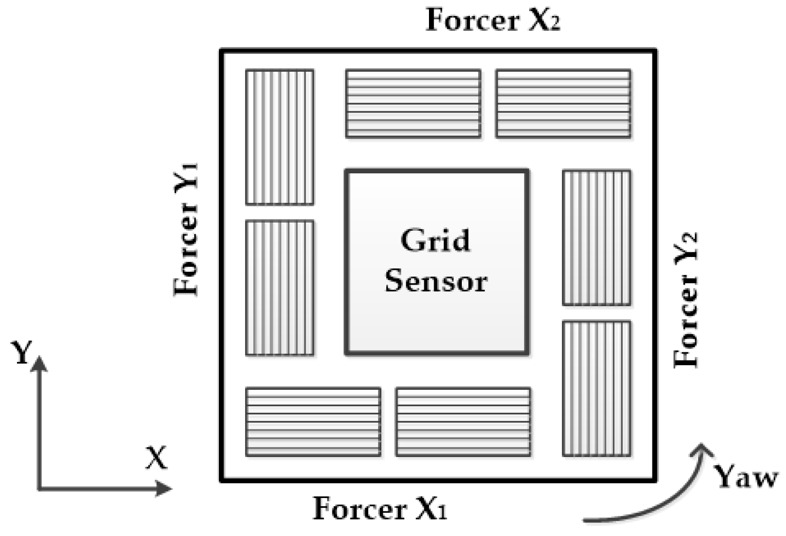
2.1. Planar Motor Modeling
The dynamic model of planar motor [3,5,6,18] can be expressed as follows:
where and
where , and are the positions of the X and Y axes, and the yaw rotation of the motor, respectively; , , and are the velocities of the X and Y axes, and the yaw rate of the motor, respectively; and are the distances from the center of the motor to the forcer; and are the forces from the two X-axis forcers; and are the forces from the two Y-axis forcers; is the force constant; and denote the motor mass and inertia, respectively; , , and are the coefficients of friction; is the tooth pitch of the platen; , , , , , , , and are the phase currents; , , , , , , , and are the input voltages in phases A and B; and R and L are the winding resistance and inductance of the motor, respectively.
2.2. Tracking-Error Dynamics with Force and Torque Modulation
We propose force and torque modulation to ensure the stability of the mechanical tracking-error dynamics:
where
- where , , and are the desired positions of the X and Y axes, and the yaw rotation of the motor, respectively; , and are the virtual velocities of the X and Y axes, and the virtual yaw rate, respectively; , and are the desired velocities of the X and Y axes, and the desired yaw rate, respectively; , and are positive constants, respectively; , and are the position-tracking errors of the X and Y axes, and yaw rotation, respectively; and are the desired forces from the two X-axis forcers; and are the desired forces from the two Y-axis forcers; and are the total forces in the X and Y directions.
The commutation scheme can be defined to generate the desired phase currents:
We also developed the nonlinear current controller to ensure the stability of the electrical tracking-error dynamics:
where , and are the H∞ state feedback controllers, which are designed in the next section using LPV synthesis.
Next, we define the tracking errors that are used to determine the tracking-error dynamics:
where , and are the velocity-tracking errors of the X and Y axes, and yaw rate, respectively; and , and are the current-tracking errors in phases A and B.
The tracking-error dynamics are obtained by combining the time derivative of the tracking errors, Equations (5) and (6); the dynamic model of the motor, Equation (1); the force and torque modulation, Equation (2); the desired phase currents, Equation (3); and the nonlinear current controller, Equation (4), as follows:
Further information on the tracking-error dynamics achieved above Equation (7) can be found in Appendix A.
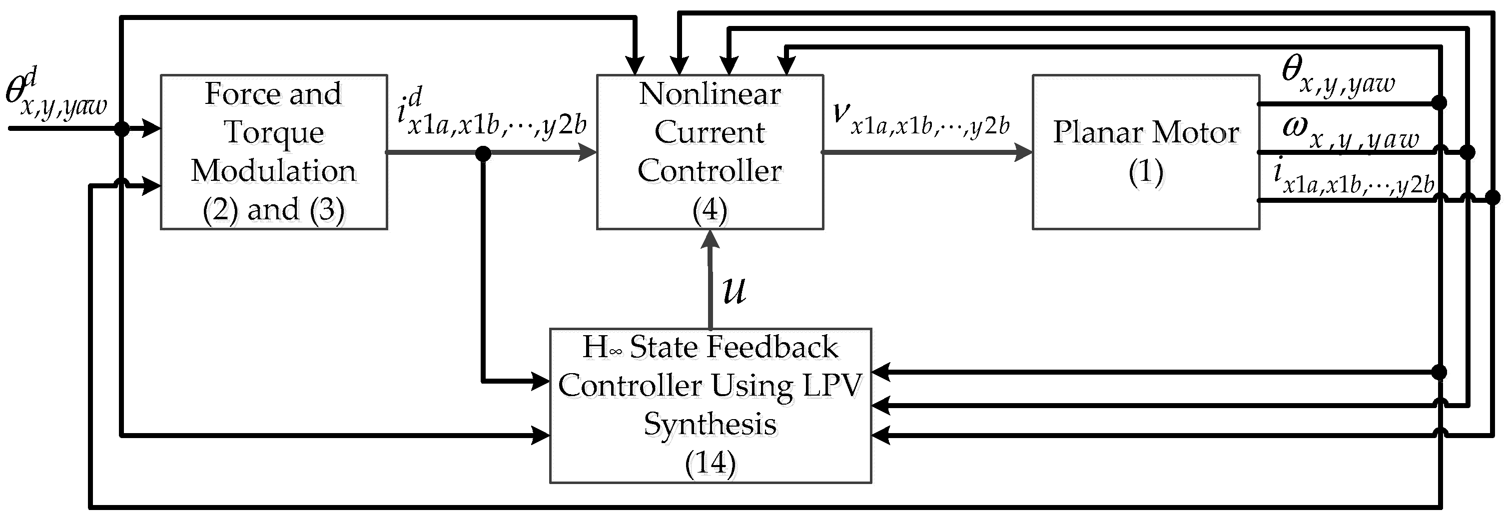
3. H∞ State Feedback Control Using LPV Synthesis
In the previous section, we discussed the derivation of force and torque modulation and the nonlinear current controller to ensure the stability of mechanical error dynamics and electrical error dynamics. In this section, we present the optimal control design of , and (defined in Section 2.2) in the form of a linear system using H∞ optimization:
The nonlinear terms and of the motor are converted into bounded linear varying parameters by the trigonometric function and are defined as follows:
Therefore, the tracking-error dynamics, Equation (7), in the LPV system can be expressed as follows:
where
Further information about the parameter-dependent matrix, , and matrix can be found in Appendix B. The varying parameters, , , , , , , , and , can be determined by measuring , and .
From Equation (8), the parameter-dependent matrix, , can be composed of as follows:
where , and The polytopic decomposition, , can be found in Appendix C.
We can determine the convex interpolation parameter vector by solving
where a vertex matrix is constructed:
Since the V, vertex matrix, cannot implement the inverse, the , expanded vertex matrix, is proposed in [18]:
Thus, the varying parameter vector can be expressed as follows:
The convex interpolation parameter vector is calculated as follows:
We then need to design the optimal controller in the form of a linear system to guarantee the stability of the tracking-error dynamics. The generalized LPV system given by Equation (8) can be defined as follows:
where is the exogenous disturbance signal, is the objective function signal, is the covariance matrix, and and are the weighting matrices of the tracking errors and control inputs, respectively.
The H∞ state feedback controller based on LPV synthesis can be expressed as follows:
where is the interpolated gain scheduling.
To determine the interpolated gain scheduling, , based on the LPV synthesis, we applied the H∞ control in the LMI technique with Assumption 1 in the optimal control design [18]:
Assumption 1.
- (A1) is stable.
- (A2) is invertible.
- (A3) .
- (A4) has no unobservable modes on the imaginary axis.
The H∞ norm of the LPV control system can be represented as follows:
The H∞ state feedback controller based on LPV synthesis determines the bound on the H∞ norm of the LPV control system with the LMI condition. The following statements are equivalent:
- There exists , such that .
- There exists , such that
By designing the H∞ state feedback controller based on an LPV system, can be interpolated by the polytopic decomposition, , in [18]. The LMI given by Equation (12) can therefore be redefined as follows:
We then define a new variable, , such that the interpolated gain scheduling based on the LPV synthesis can be recovered by with the following LMI condition:
Now, we can obtain the interpolated gain scheduling, , based on the parameter-dependent matrix, , in Equation (9) and the convex interpolation parameter in Equation (10), as follows:
Then the H∞ state feedback controller with the interpolated gain scheduling in Equation (13) based on LPV synthesis can be expressed as follows:
Remark 1.
can be computed offline since each value uses a polytopic decomposition matrix, , with fixed constant values, according to Equation (12). Therefore, according to Equation (13), we only need to find the interpolation variables to implement the controller in real time. Therefore, it is not necessary to always find a solution that meets the given LMI condition to generate the control input.
The block diagram of the proposed control method is shown in Figure 2. The proposed method consists of force and torque modulation, a nonlinear current controller, and an H∞ state feedback controller based on LPV synthesis.
Figure 2.
Block diagram of the proposed control method.
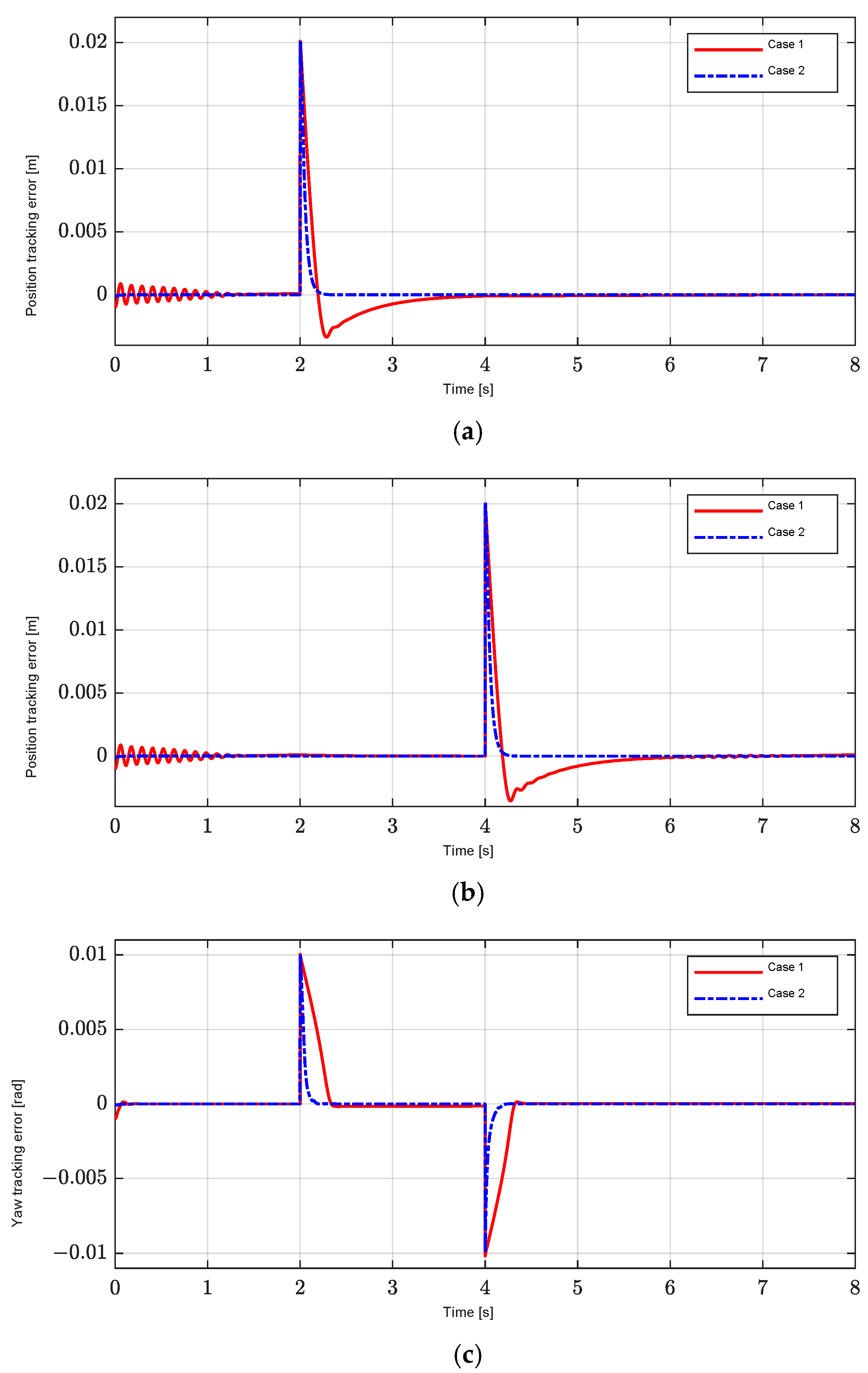
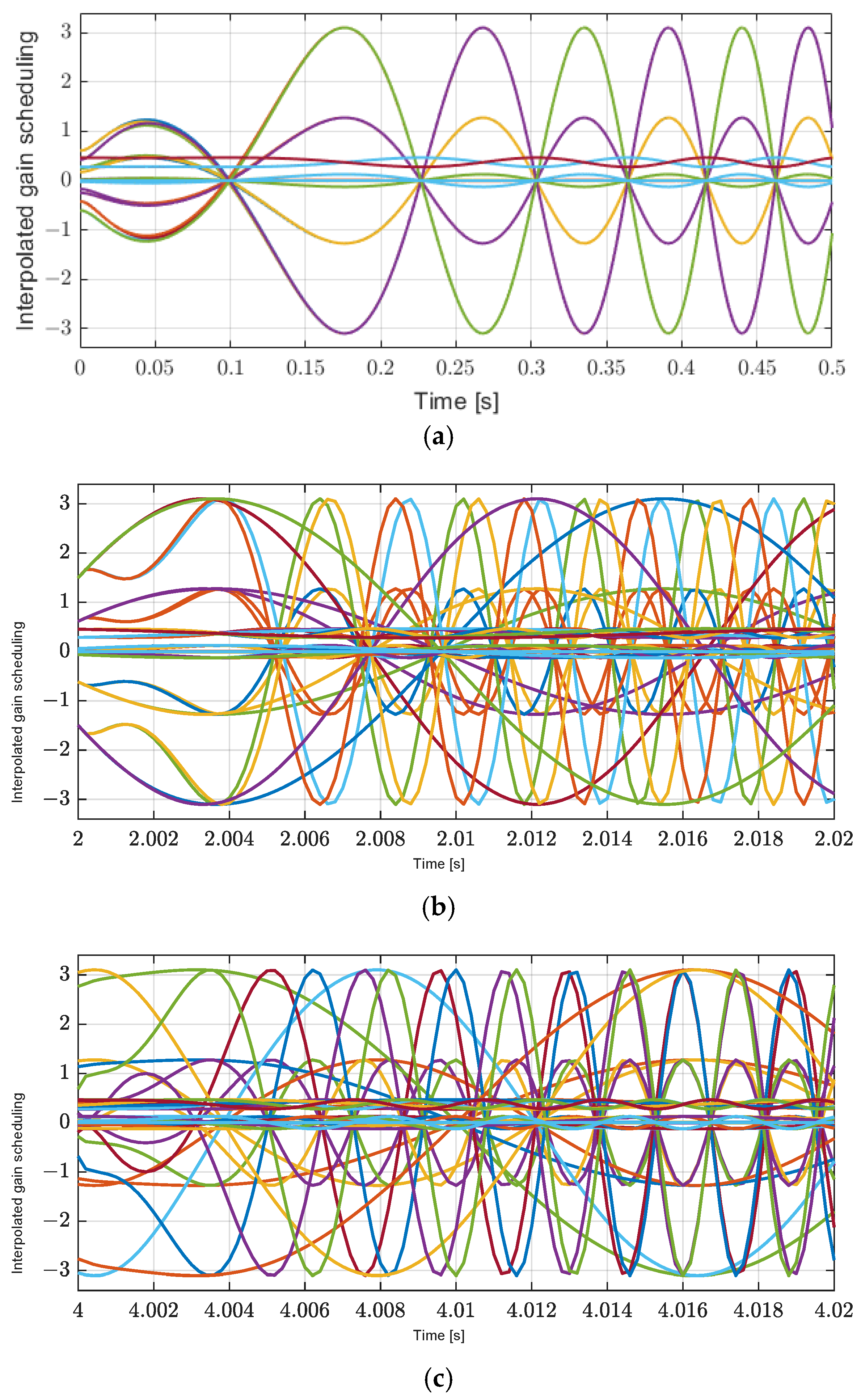
4. Simulation Results
We conducted simulations to evaluate the performance of the proposed control method using MATLAB/Simulink. The planar motor parameters and control gains are listed in Table 1. To verify the position-tracking performance of the proposed controller without disturbance estimation, we conduct simulations with different position profiles and disturbances. The desired yaw profile is set to 0 rad as follows:
Table 1.
Parameters of the planar motor [3,18] and controller gains.
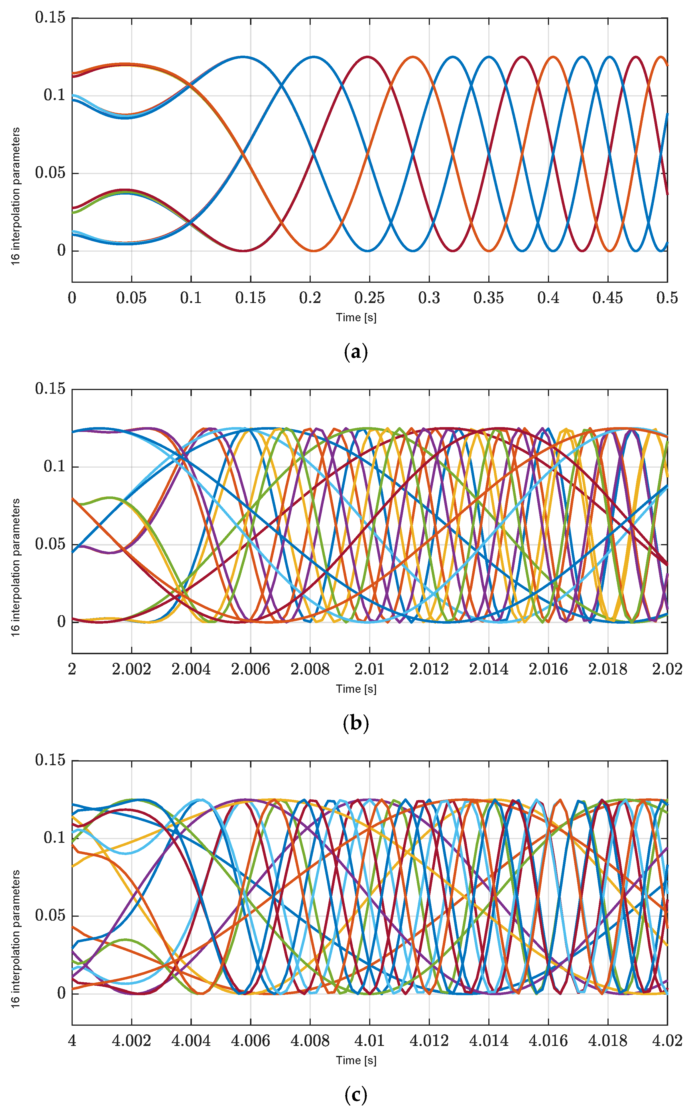
4.1. Seventh-Order Reference Position Profiles
For our analysis of the performance of the proposed LPV controller with respect to seventh-order reference position profiles in Figure 3 under the influence of exogenous disturbances, including load forces and load torque of the X axis at 2 s, the Y axis at 4 s, and the yaw with a period from 2 to 4 s in Figure 4a–c, the sixteen interpolation parameters of eight nonlinearly varying parameters are shown in Figure 5a–c. These results confirm the satisfaction of the convexity constraints that each interpolation is greater than zero and their sum is 1. These results also confirm that the proposed LPV controller is properly implemented.
Figure 3.
Seventh-order reference position profiles for X and Y axes.
Figure 4.
Exogenous disturbance. (a) X-axis exogenous disturbance, , at 2 s. (b) Y-axis exogenous disturbance, , at 4 s. (c) Yaw exogenous disturbance, , with a period from 2 to 4 s.
Figure 5.
Sixteen interpolation parameters for each polytopic decomposition. (a) Zoom-in of the X axis at the start time of interpolation parameters. (b) Zoom-in of the X axis at 2 s of interpolation parameters. (c) Zoom-in of the X axis at 4 s of interpolation parameters.
Validation of the proposed method with respect to the seventh-order reference position profiles in Figure 3 under the influence of exogenous disturbances, including 40% of the load forces and 20% of the load torque in Figure 4, compared to the desired positions in the following two cases:
- Case 1: Conventional PID controller.
- Case 2: Proposed control method.
To analyze the performance of position-tracking errors, Figure 6a–c show the simulation results of Cases 1 and 2. In both cases, the position-tracking errors converge to zero before 2 s in Figure 6a,c and zero before 4 s in Figure 6b; however, Case 1 has an oscillation and a longer transient response than Case 2. For the position-tracking errors of the X and Y axes under the influence of exogenous disturbances including load forces at 2 s in Figure 4a and 4 s in Figure 4b, the PID controller in Case 1 has a longer settling time and larger overshoot during the acceleration and deceleration periods than the method proposed in Figure 6a,b because the large and fixed controller gains result in poor transient performance of the position-tracking controller. We confirm that Case 1 has a poor transient performance in position control. In contrast, in Case 2, the position tracking-error performance of the X and Y axes quickly converges to zero after 2 s in Figure 6a and 4 s in Figure 6b in the steady-state region under the influence of disturbances. In addition, the position tracking-error performance of the X and Y axes in Case 2 is improved under the yaw rotation disturbance caused at 2 and 4 s. As shown in Figure 6c, the yaw motion in Case 2 is effectively controlled under the influence of exogenous disturbance to the load torque in Figure 4c, with a period from 2 to 4 s better than Case 1, because the controller uses the interpolated gain scheduling in Equation (13), as shown in Figure 7, to regulate the position-tracking errors, and the effectiveness of H∞ control is ensured by using the H∞ norm in Equation (11).
Figure 6.
Position tracking-error performance for seventh-order reference. (a) X-axis position-tracking error, . (b) Y-axis position-tracking error, . (c) Yaw-tracking error, .
Figure 7.
Interpolated gain scheduling for each polytopic decomposition. (a) Zoom-in of the X axis at the start time of interpolated gain scheduling. (b) Zoom-in of the X axis at 2 s of interpolated gain scheduling. (c) Zoom-in of the X axis at 4 s of interpolated gain scheduling.
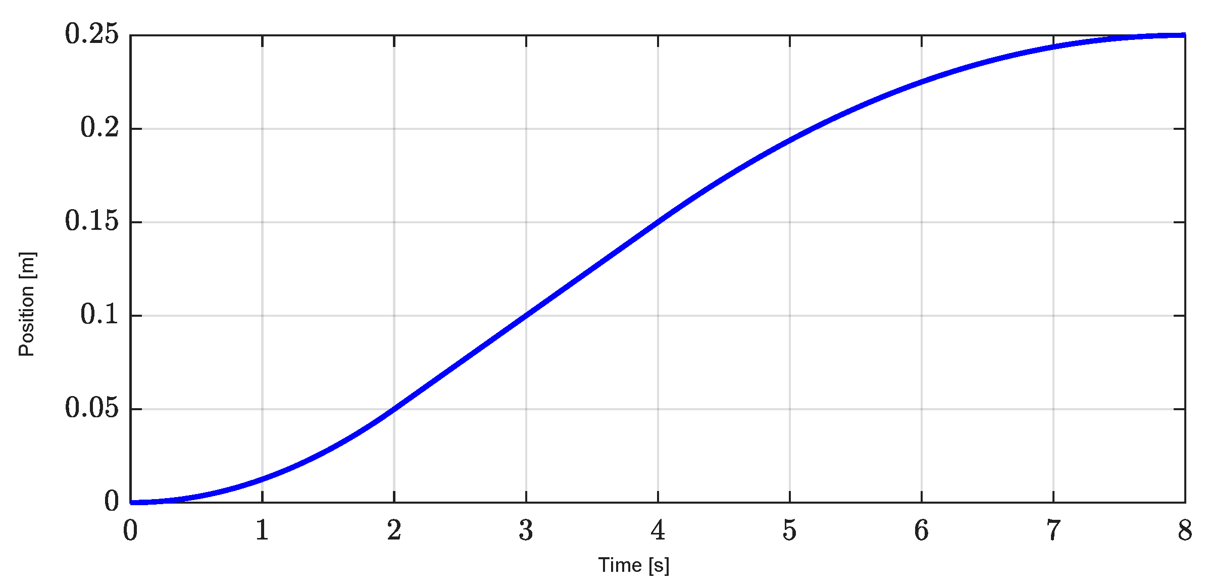
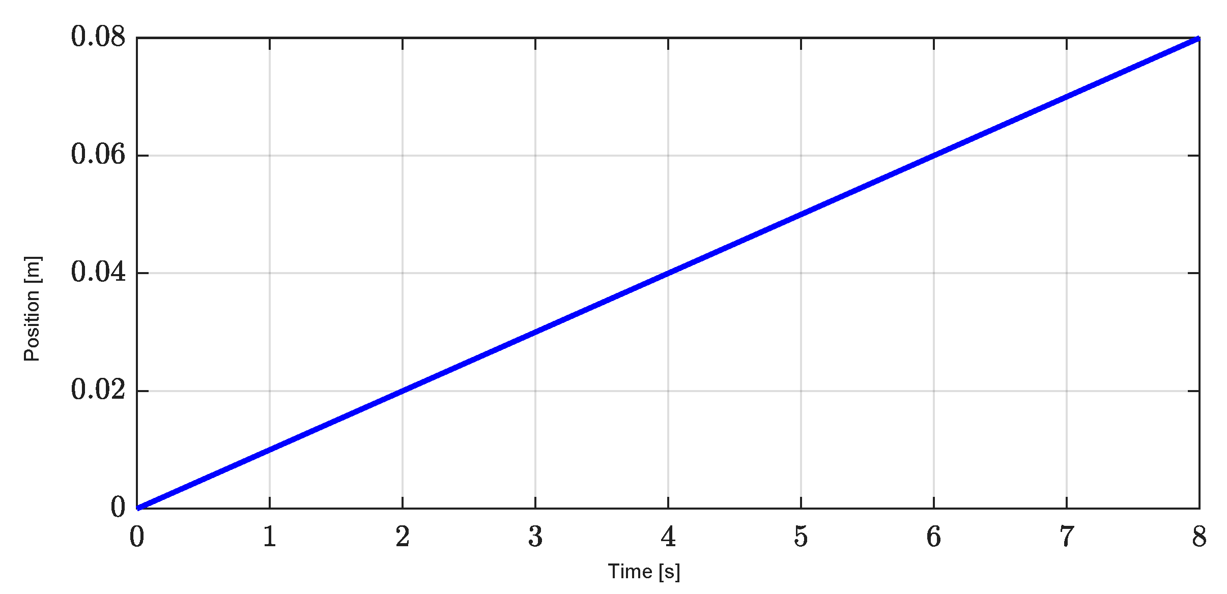
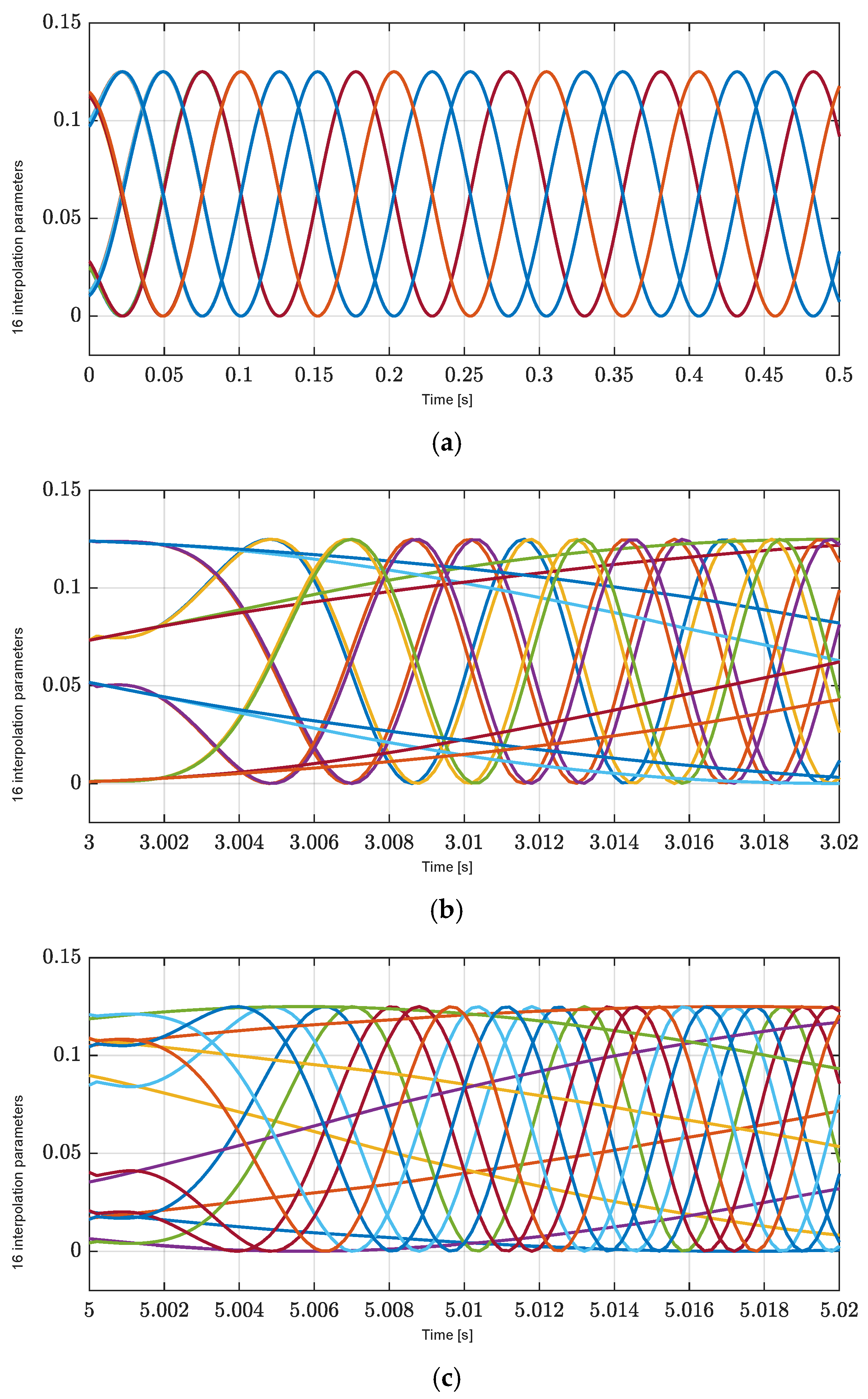
4.2. Ramp Reference Position Profiles
Similar to Section 4.1 for the performance analysis of the proposed LPV controller, we perform simulations with respect to ramp reference position profiles in Figure 8 under the influence of exogenous disturbances, including load forces and load torque of the X axis at 3 s, the Y axis at 5 s, and the yaw with a period from 3 to 5 s in Figure 9a–c. The sixteen interpolation parameters of eight nonlinearly varying parameters are shown in Figure 10a–c. These results also confirm the satisfaction of the convexity constraints that each interpolation is greater than zero and their sum is 1. These results also confirm that the proposed LPV controller is properly implemented.
Figure 8.
Ramp reference position profiles for X and Y axes.
Figure 9.
Exogenous disturbance. (a) X-axis exogenous disturbance, , at 3 s. (b) Y-axis exogenous disturbance, , at 5 s. (c) Yaw exogenous disturbance, , with a period from 3 to 5 s.
Figure 10.
Sixteen interpolation parameters for each polytopic decomposition (a) Zoom-in of the X axis at the start time of interpolation parameters. (b) Zoom-in of the X axis at 3 s of interpolation parameters. (c) Zoom-in of the X axis at 5 s of interpolation parameters.
In this subsection, we also compare the proposed method (Case 2) with a PID controller (Case 1). However, the simulation results are conducted with different position profiles in Figure 8 and disturbances in Figure 9, including 40% of the load forces and 20% of the load torque, compared to the desired positions, to validate the effectiveness of the proposed method under different position profiles and disturbances.
Figure 11a–c show the performance of the position-tracking errors of Cases 1 and 2. In both cases, the position-tracking errors converge to zero before 3 s in Figure 11a,c and zero before 5 s in Figure 11b; however, Case 1 has an oscillation and a longer transient response than Case 2. For the position-tracking errors of the X and Y axes under the influence of exogenous disturbances, including load forces at 3 s in Figure 9a and 5 s in Figure 9b, the position-tracking error performance of the X and Y axes in Case 2 quickly converges to zero in the steady-state region after 3 s in Figure 11a and 5 s in Figure 11b. The method proposed has a better transient position-control performance than the PID controller in Case 1. Since the PID controller has large and fixed controller gains, this results in the poor transient performance of the position-tracking controller. In addition, the position tracking-error performance of the X and Y axes in Case 2 is improved under the yaw rotation disturbance caused at 3 and 5 s.
Figure 11.
Position tracking-error performance for ramp reference. (a) X-axis position-tracking error, . (b) Y-axis position-tracking error, . (c) Yaw-tracking error, .
On the other hand, due to the fact that the controller also uses the interpolated gain scheduling in Equation (13), as shown in Figure 12, to regulate the position-tracking errors, and the effectiveness of H∞ control is also ensured by using the H∞ norm in Equation (11), the yaw motion in Case 2 is also controlled more effectively than in Case 1 under the influence of exogenous disturbances to the load torque in Figure 11c.
Figure 12.
Interpolated gain scheduling for each polytopic decomposition. (a) Zoom-in of the X axis at the start time of interpolated gain scheduling. (b) Zoom-in of the X axis at 3 s of interpolated gain scheduling. (c) Zoom-in of the X axis at 5 s of interpolated gain scheduling.
Based on simulation results with different position profiles and disturbances in Section 4.1 and Section 4.2, we confirm that the proposed control method improves position-tracking performance and attenuates disturbances without requiring disturbance estimation. To show the performance improvement of the proposed controller, the results comparing the time required for the system to converge steady state are summarized in Table 2 and Table 3.
Table 2.
Comparison of tracking performance for two cases in seven-order reference.
Table 3.
Comparison of tracking performance for two cases in ramp reference.
5. Conclusions
In this paper, we presented the controller in the form of a linear system without disturbance estimation to improve the position-tracking performance and disturbance attenuation for planar motors. The force and torque modulation and commutation scheme in the form of LPV synthesis stabilized the mechanical dynamics and generated the desired phase currents. The interpolated gain-scheduling controller based on LPV synthesis was determined using H∞ control in the LMI technique and stabilized the electrical dynamics. Simulation results with different position profiles and disturbances were carried out to verify the effectiveness of the proposed method by comparing with a PID controller. In the steady-state region, the position-tracking errors of the X and Y axes converged to zero more quickly, and the yaw motion was well controlled with the proposed control method under the influence of exogenous disturbances, including load forces and load force. The interpolated gain-scheduling controller had the advantage of attenuating disturbance without disturbance estimation in the motor.
A possible future research direction is to compare the closed-loop performance of the proposed control method with other robust control methods. Since the proposed control method maintained a good tracking performance under input disturbances, it can be comparable to other robust control methods.
Author Contributions
K.H.S. and K.P. designed the algorithm and developed the simulation; Y.L. and Y.S.S. provided guidance in designing the algorithm. All authors have read and agreed to the published version of the manuscript.
Funding
This research received no external funding.
Institutional Review Board Statement
Not applicable.
Informed Consent Statement
Not applicable.
Data Availability Statement
Data will be made available on request.
Acknowledgments
This paper was supported in part by the Korea Institute of Energy Technology Evaluation and Planning grant funded by the Korea Government (MOTIE) (20224000000160, DC Grid Energy Innovation Research Center), in part by the MSIT (Ministry of Science and ICT), Korea, under the ITRC (Information Technology Research Center) support program (IITP-2024-RS-2024-00437756) supervised by the IITP (Institute for Information & Communications Technology Planning & Evaluation).
Conflicts of Interest
The authors declare no conflict of interest.
Appendix A
The tracking-error dynamics are obtained by combining the time derivative of the tracking errors, Equations (5) and (6); the dynamic model of the motor, Equation (1); the force and torque modulation, Equation (2); the desired phase currents, Equation (3); and the nonlinear current controller, Equation (4), in detail as follows:
The time derivative of the tracking errors in Equations (5) and (6) is as follows:
From Equation (2), we obtain the following:
where
From in Equations (1), (A1) and (A2), we obtain the following:
From in Equations (4), (A3) and (A4), we obtain the tracking-error dynamics in Equation (7).
Appendix B
The parameter-dependent matrix, , and can be defined as follows:
where
and , where
Appendix C
The polytopic decomposition, , can be defined as follows:
where
and are real fixed nodal matrices related to and the extreme values of the varying parameters.
References
- Zheng, T.; Xu, F.; Lu, X.; Xu, X. A new multi-objective optimization method of magnetic levitation planar motor. IEEE Trans. Magn. 2019, 55, 1–8. [Google Scholar] [CrossRef]
- Zhang, Y.; Ding, K.; Du, S. Design study of a high loading superconducting magnetically levitated planar motor. IEEE Trans. Appl. Supercond. 2021, 31, 2021–2024. [Google Scholar] [CrossRef]
- Su, K.H.; Yim, J.; Kim, W.; Lee, Y. Lyapunov-based controller using nonlinear observer for planar motors. Mathematics 2022, 10, 2177. [Google Scholar] [CrossRef]
- Ou, T.; Hu, C.; Zhu, Y.; Zhang, M. Generation mechanism and decoupling strategy of coupling effect in maglev planar motor. IEEE/ASME Trans. Mechatron. 2023, 28, 781–791. [Google Scholar] [CrossRef]
- Krishnamurthy, P.; Khorrami, F. Robust Adaptive Control of Sawyer Motors Without Current Measurements. IEEE/ASME Trans. Mechatron. 2004, 9, 689–696. [Google Scholar] [CrossRef]
- Krishnamurthy, P.; Khorrami, F.; Ng, T.L.; Cherepinsky, I. Control Design and Implementation for Sawyer Motors Used in Manufacturing Systems. IEEE Trans. Control Syst. Technol. 2011, 19, 1464–1478. [Google Scholar] [CrossRef]
- Li, X.; Zhu, H.; Ma, J.; Teo, T.J.; Teo, C.S.; Tomizuka, M.; Lee, T.H. Data-driven multiobjective controller optimization for a magnetically levitated nanopositioning system. IEEE/ASME Trans. Mechatron. 2020, 25, 1961–1970. [Google Scholar] [CrossRef]
- Ou, T.; Hu, C.; Zhu, Y.; Zhang, M.; Zhu, L. Intelligent feedforward compensation motion control of maglev planar motor with precise reference modification prediction. IEEE Trans. Ind. Electron. 2021, 68, 7768–7777. [Google Scholar] [CrossRef]
- Proimadis, I.; Custers, C.H.H.M.; Toth, R.; Jansen, J.W.; Butler, H.; Lomonova, E.; Hof, P. Active deformation control for a magnetically levitated planar motor mover. IEEE Trans. Ind. Appl. 2022, 58, 242–249. [Google Scholar] [CrossRef]
- Fu, H.; Hu, C.; Yu, D.; Zhu, Y.; Zhang, M. Cascaded iterative learning motion control of precision maglev planar motor with experimental investigation. ISA Trans. 2023, 139, 463–474. [Google Scholar] [CrossRef]
- Huang, S.D.; Chen, L.; Cao, G.Z.; Wu, C.; Xu, J.; He, Z. Predictive position control of planar motors using trajectory gradient soft constraint with attenuation coefficients in the weighting matrix. IEEE Trans. Ind. Electron. 2021, 68, 821–837. [Google Scholar] [CrossRef]
- Huang, S.D.; Cao, G.Z.; Xu, J.; Cui, Y.; Wu, C.; He, J. Predictive position control of long-stroke planar motors for high-precision positioning applications. IEEE Trans. Ind. Electron. 2021, 68, 796–811. [Google Scholar] [CrossRef]
- Yim, J.; You, S.; Lee, Y.; Kim, W. Chattering Attenuation Disturbance Observer for Sliding Mode Control: Application to PMSM. IEEE Trans. Ind. Electron. 2023, 70, 5161–5170. [Google Scholar] [CrossRef]
- Hou, Q.; Ding, S. GPIO based super-twisting sliding mode control for PMSM. IEEE Trans. Circuits Syst. II Exp. Briefs 2021, 68, 747–751. [Google Scholar] [CrossRef]
- Tian, D.; Xu, R.; Sariyildiz, E.; Gao, H. An adaptive switching-gain sliding-mode-assisted disturbance observer for high-precision servo control. IEEE Trans. Ind. Electron. 2021, 69, 1762–1772. [Google Scholar] [CrossRef]
- Xie, Y.; Qiao, J.; Yu, X.; Guo, L. Dual-disturbance observers-based control for a class of singularly perturbed systems. IEEE Trans. Syst. Man. Cybern. Syst. 2022, 52, 2423–2434. [Google Scholar] [CrossRef]
- Wang, Y.; Yu, H.; Liu, Y. Speed-current single-loop control with overcurrent protection for PMSM based on time-varying nonlinear disturbance observer. IEEE Trans. Ind. Electron. 2022, 69, 179–189. [Google Scholar] [CrossRef]
- Su, K.H.; Byeon, K.; Kim, W.; Lee, Y. LPV H∞ control with an augmented nonlinear observer for sawyer motors. Mathematics 2022, 10, 18. [Google Scholar] [CrossRef]
Disclaimer/Publisher’s Note: The statements, opinions and data contained in all publications are solely those of the individual author(s) and contributor(s) and not of MDPI and/or the editor(s). MDPI and/or the editor(s) disclaim responsibility for any injury to people or property resulting from any ideas, methods, instructions or products referred to in the content. |
© 2024 by the authors. Licensee MDPI, Basel, Switzerland. This article is an open access article distributed under the terms and conditions of the Creative Commons Attribution (CC BY) license (https://creativecommons.org/licenses/by/4.0/).