Abstract
In recent years, increasing attention has been given to reducing energy consumption in hydraulic excavators, resulting in extensive research in this field. One promising solution has been the integration of hydrostatic transmission (HST) and hydraulic pump/motor (HPM) configurations in parallel systems. However, these systems face challenges such as noise, throttling losses, and leakage, which can negatively impact both tracking accuracy and energy efficiency. To address these issues, this paper introduces an intelligent real-time prediction framework for system positioning, incorporating particle swarm optimization (PSO), long short-term memory (LSTM), a gated recurrent unit (GRU), and proportional–integral–derivative (PID) control. The process begins by analyzing real-time system data using Pearson correlation to identify hyperparameters with medium to strong correlations to the positioning parameters. These selected hyperparameters are then used as inputs for forecasting models. Independent LSTM and GRU models are subsequently developed to predict the system’s position, with PSO optimizing four key hyperparameters of these models. In the final stage, the PSO-optimized LSTM-GRU models are employed to perform real-time intelligent predictions of motion trajectories within the system. Simulation and experimental results show that the model achieves a prediction deviation of less than 3 mm, ensuring precise real-time predictions and providing reliable data for system operators. Compared to traditional PID and LSTM-GRU-PID controllers, the proposed controller demonstrated superior tracking accuracy while also reducing energy consumption, achieving energy savings of up to 10.89% and 2.82% in experimental tests, respectively.
Keywords:
energy management; fuel consumption; hybrid hydraulic excavators; energy recuperation; particle swarm optimization; gated recurrent unit; long short-term memory; tracking precision MSC:
93C10; 93D21
1. Introduction
To tackle the challenges of energy shortages and environmental degradation, innovative approaches are crucial, especially in sectors like infrastructure and agriculture, where heavy equipment plays a major role in exacerbating these problems [1]. Considering the considerable contribution of heavy machinery to emissions, prioritizing research on technologies that improve energy efficiency and lower emissions is critical, with a special emphasis on hydraulic excavators (HEs) [2].
A commonly employed solution is the energy regeneration system (ERS), which captures and reuses potential energy in HEs. The boom system, specifically, contains the highest level of potential energy, comprising as much as 51% of the total recoverable energy, largely because of gravitational forces acting during the lowering process [3]. ERSs are typically categorized into three types: mechanical, hydraulic, and electric systems. The implementation of systems like electric energy regeneration systems (EERSs) and hydraulic energy regeneration systems (HERSs) has played a crucial role in enhancing the efficiency of hybrid hydraulic excavators (HHEs) [4]. In an EERS, an electric generator can be utilized to harness and store recovered energy, with storage typically managed by batteries or supercapacitors [5]. When it comes to HERSs, hydraulic valves are employed to store regenerated energy in a hydraulic accumulator [6,7,8]. Overall, ERSs are highly effective in reducing energy consumption in HEs. However, integrating components for capturing, storing, and reusing energy naturally leads to higher investment costs, along with increased size and complexity of the hardware and control systems. An electric hybrid hydraulic excavator was proposed to improve energy efficiency by optimizing the efficiency of the internal combustion engine (ICE) and hydraulic pump (HPu) [9]. In this context, Yu also introduced the electrical hydraulic continuously variable powertrain (EHCVP), which integrates an ICE with an electric motor/generator (EMG) to drive the boom system. The EHCVP design enables the adjustment of the ICE’s operating speed to achieve maximum performance. However, it is crucial to note that the torque control range of the engine at elevated speeds is limited by the HPu’s maximum displacement. When operating under heavy loads and at moderate speeds, the EHCVP faces challenges in maintaining optimal efficiency of the ICE, highlighting the need for further research. Additionally, while these systems emphasize energy savings, they often overlook the challenge of achieving precise control of the actuator’s position.
During the operation of the HEs, accurately controlling the position trajectory of the boom cylinder presents significant challenges, especially when adjustments are made solely based on manual experience. Advancements in fields like artificial intelligence (AI), big data, and control theory have led to the development of an integrated control strategy, which integrates an adaptive neuro-fuzzy inference system (ANFIS) with a proportional–integral–derivative (PID) controller to tackle these challenges [10,11,12]. In a related study, Song et al. [13] introduced a quantum particle swarm optimization algorithm with hybrid adaptive features (HAQPSO) for tuning the parameters of PID controllers, which resulted in improved accuracy for trajectory control in excavator actuators.
Similarly, Ha et al. [14] introduced a neural network–fractional order PID controller (NNFOPID) controller, which was validated on a physical rig simulating the motion of a hydraulic excavator’s boom cylinder. In another approach, Zohaib et al. [15] introduced the HPSO-SSM-RBFNN algorithm, which is effective in identifying and predicting nonlinear systems by employing a radial basis function neural network (RBFNN) in conjunction with a powerful hybrid particle swarm optimization (HPSO) method. Furthermore, Xuanyu et al. [16] presented the BWO-LSTM-GRU model, designed to provide time-sensitive position parameters that enhance operators’ ability to adapt to complex and dynamic working environments. Additionally, Han et al. [17] proposed the GPSO+DFNN algorithm, which demonstrated considerable effectiveness and precision in identifying and controlling nonlinear systems, particularly those with significant time delays. Recently, Wang et al. [18] proposed a dual-competition-based swarm optimizer (DCS-PSO) that efficiently preserves swarm diversity and balances exploration and exploitation in large-scale optimization problems. Likewise, Luo et al. [19] conducted a comparative analysis of heuristic intelligent optimization algorithms, including PSO, WDO, GWO, and OOBO, evaluating their stability, convergence, and computational complexity. Furthermore, a new metaheuristic called the Hiking Optimization Algorithm (HOA) was introduced by Wei et al. [20], inspired by hiking activity to solve optimization problems across various landscapes, which demonstrated competitiveness against 14 well-known metaheuristics. In another study, Owais et al. [21] developed a two-archive Harris Hawk optimization (TwoArchHHO) to solve many-objective optimal power flow (MaOOPF) problems, outperforming existing algorithms across multiple test systems. Additionally, Qu et al. [22] proposed the artificial protozoa optimizer (APO), inspired by the survival mechanisms of protozoa, which showed highly competitive results in solving both continuous and discrete optimization problems. The main drawbacks of previous algorithms for hydraulic systems include difficulties in handling the strong nonlinearity and time delays inherent in these systems. Additionally, the computational complexity of optimization methods may hinder real-time performance, and the algorithms may struggle to adapt to noise and environmental fluctuations in hydraulic systems.
Building upon the previous analysis, this paper emphasizes two major advancements in the energy efficiency of boom systems. Firstly, it introduces an advanced structural design incorporating an HST, which significantly improves torque control and the adaptability of the ICE. By integrating the HST with a planetary gearbox and an HPM, the design broadens the operational range of the ICE, resulting in superior performance compared to existing systems. This innovation not only optimizes engine efficiency but also enables the handling of heavier loads, marking a substantial improvement in operational capabilities. Secondly, this paper proposes a novel control strategy called Particle Swarm Optimization–Long Short-Term Memory–Gated Recurrent Unit–Proportional Integral Derivative (PSO-LSTM-GRU-PID). In this approach, real-time data from HEs are initially processed and utilized as input variables for predictive modeling. An LSTM-GRU-PID model is then specifically developed to predict the position parameters of the boom cylinder, with hyperparameter optimization performed through PSO. The optimized PSO-LSTM-GRU-PID models are subsequently applied to achieve intelligent real-time motion trajectory predictions at four different positions of the boom cylinder. The simulation outcomes show that the position prediction model consistently achieves a deviation of less than 3 mm, effectively meeting the requirements for real-time prediction and providing critical real-time data support for HE operators. The key contributions of this paper include the following:
- This study represents the first implementation of the PSO-LSTM-GRU-PID controller on a physical test bench designed to simulate the movement of the boom cylinder in a hydraulic excavator, alongside a simulation model in AMESim software 2310.The key benefit of this controller lies in its model-free nature, allowing it to be implemented without the need for system identification, thereby reducing the computational load and hardware requirements on the hydraulic excavator.
- The PSO algorithm was utilized to optimize four hyperparameters within the LSTM-GRU-PID controller, aiming to improve tracking accuracy and energy efficiency. The effectiveness of the proposed controller was confirmed through both co-simulation and experimental testing.
- In comparison to the PID and LSTM-GRU-PID controllers, the proposed controller demonstrated superior tracking accuracy while also reducing energy consumption, achieving savings of up to 10.89% and 2.82% in experimental tests, respectively.
The organization of this paper is as follows. First, Section 2 details the proposed enhancements to the EHCVP powertrain. Section 3 presents the fundamental theorem for hybrid algorithm control. Section 4 presents the simulation and experimental results. Finally, the conclusions are summarized in Section 5.
2. System Description
2.1. Powertrain Calculation
To improve energy-saving efficiency, this study introduces a novel system specifically designed for the boom mechanism. As depicted in Figure 1, the new design aims to reduce the ICE energy consumption during boom extension while also enabling dual energy regeneration during boom retraction. The HST and HPM serve as the two pivotal components in the proposed system. The output shaft of the planetary gear is precisely managed by both the HST and HPM, allowing for versatile integration with either the HPM or the hydraulic motor (HM). This innovative system introduces control mechanisms that have not been explored in previous designs. The refined control strategy supports smooth transitions between two operational modes, ‘boom-up’ and ‘boom-down’, regardless of how the HST is connected to the HPM. This paper presents an advanced electrical hydraulic continuously variable powertrain as shown in Figure 1. In practical engineering scenarios, the proposed system enhances fuel economy across various speeds by effectively adjusting to different operational conditions.
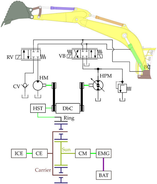
Figure 1.
Structure of the proposed system.
In the proposed system setup, the ICE, EMG, and HST components correspond to the carrier, sun, and ring gears, respectively. The rotational speeds of these gears are determined by Equation (1) [9]:
where the number of teeth and speed are considered, denoted as and for the ring gear and and for the sun gear. The carrier’s speed is indicated by .
The HST ratio is described by Equation (2):
where denotes the speed of the HPM’s speed and indicates the HST ratio. The joystick signal specifies the desired flow rate, as described by Equation (3):
where represents the volumetric efficiency of the HPM and indicates its flow rate. By applying Equations (2) and (3), the appropriate HPM displacement and HST ratio can be identified based on the necessary flow rate. This approach leads to numerous potential combinations for the ICE and EMG speeds, as described by Equation (1).
The torque for each gear is determined by the Equation (4) [9]:
where , and denote the torques for the ring gear, sun gear, and carrier, respectively. The HPM’s torque is influenced by the pressure at its output, as shown in Equation (5):
where represents the torque of the HPM, and indicates the pressure at the HPM’s output. Additionally, specifies the HPM’s displacement, while denotes its hydro-mechanical efficiency. The torque of the HPM, symbolized by , influences the torque of the ring gear.
Utilizing Equations (4) and (5), we can calculate and , which are then shown in Equations (6) and (7):
The transmission ratio for the whole system is defined in the following way:
where is the ratio of the planetary gearbox.
In Equations (6) and (7), the cylinder pressure is measured by the pressure sensor in the proposed system. Consequently, an EMS is necessary for the proposed system. Moreover, Equation (9) provides the calculation for the pressure :
where F denotes the force exerted on the boom cylinder. The rod chamber’s area is indicated by .
During lifting and lowering operations, the cylinder’s speed is directly affected by the operator’s control input, as explained in Equation (10):
where denotes the operator’s control input signal, and and indicate the desired and maximum velocities of the cylinders, respectively. The value ranges from 0 to . The maximum velocity is . Additionally, the required flow rate can be calculated using Equation (11):
2.2. Investigation of Key Parameters
The proposed system utilizes the components listed in Table 1, which presents the parameters for the main components. In the proposed system, a variable HPM is employed. The hydro-mechanical and volumetric efficiencies of the HPM, as well as the efficiency map of the fixed displacement HM, can be found in [9]. The ICE and the EMG play crucial roles in supplying power to the system. The efficiency maps for these components can be found in [23]. Additionally, it is essential to consider the battery’s capacity. To extend the lifespan of the battery and prevent severe depletion or excessive charging, the operational range is usually maintained between 30 and 90% of its total capacity [24].

Table 1.
Parameters of the key components.
2.3. Energy Management Strategy
As mentioned earlier, the EMS has a significant impact on the energy efficiency of the proposed system. To improve this efficiency, an ECMS has been applied. This ECMS was used with an HE to identify the conditions that resulted in minimal fuel consumption. Due to the distinct characteristics of the proposed system, an ECMS is recommended for the EMS. The cost function associated with this ECMS is described in Equation (12) [25]:
where represents the total fuel usage, and and are the energy usages of the engine and electric motor, respectively. The function translates electrical usage into corresponding fuel usage, as described in Equation (13) [26]:
where and denote the coefficients for discharge and charging, respectively. These coefficients can be defined as shown in Equation (14) [27]:
where represents the ICE efficiency; indicates the efficiency of the motor while generating power; denotes the motor’s efficiency while driving; and and are the battery’s charge and discharge efficiencies, respectively.
The SOC of a battery is defined in Equation (15) [28], which considers several factors: the initial , the coulombic efficiency , the power output , and the battery’s nominal energy capacity :
where can be expressed by Equation (16):
In the ECMS, and can be expressed by Equations (17) and (18) [29]:
where , and represent the efficiencies of the engine, motor, and battery, respectively. , refer to the ICE’s output and the battery’s equivalent energy output. According to Equation (18), when the EMG operates as a motor, the speed and torque are in the same direction (). On the other hand, when (), it signifies that the EMG is operating as a generator. The ECMS for the proposed system is different from that of a typical vehicle due to its unique design. Calculating the ECMS requires considering the efficiencies of both the hydraulic system and the HST. The ECMS outlined in Equations (12), (17) and (18) includes the efficiencies of the ICE, battery, HPM, battery SOC, HST efficiency , and HST gear ratio. The proposed ECMS integrates the traditional ECMS with the unique attributes of the proposed system, aiming to lower fuel consumption.
3. Fundamental Theorem for Hybrid Algorithm Control
In order to improve tracking accuracy and energy efficiency in the proposed system, coordinated management of the components is implemented using the PSO-LSTM-GRU-PID controller. Specifically, valve control improves the cylinder’s positioning accuracy by modifying the opening size of the control valve. At the same time, the HST is responsible for regulating the system’s energy consumption. The structure of the PSO-LSTM-GRU-PID algorithm is illustrated in Figure 2, and its operation is explained in detail in the following section. In the diagram, represents the desired value (reference input), such as the target position or velocity for the system to achieve. is the actual output, the measured value from the system, used as feedback to compare against and adjust the control to minimize error.
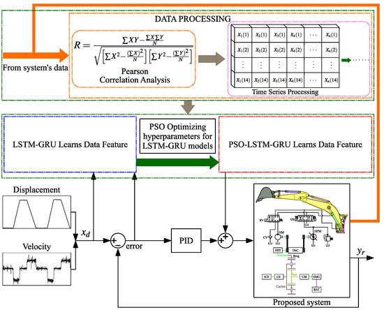
Figure 2.
Design diagram of proposed system position prediction scheme.
3.1. Particle Swarm Optimization (PSO) Algorithm
PSO is an effective stochastic search algorithm that simulates the collective behavior seen in schools of fish and flocks of birds [15,18]. In PSO, each particle represents a potential solution within the search space. In this study, each particle refines its trajectory based on its best-known position and the best-known positions of other particles to eventually arrive at a global optimal solution that is sought. A vector represents the prior position of particle i during the search process, as shown in the following Equation (19):
where, D defines the dimension of the search space and N represents the swarm size, with . Each particle is associated with a velocity, as described by Equation (20):
The velocity of each particle is influenced by its stored memory, allowing it to explore the entire search space. Let pbesti represent the best previous position of particle i, denoted as pbesti = pbesti1 =, pbesti2, pbesti3,… pbestiD. Similarly, gbesti = gbest1, gbest2,… gbestD refers to the optimal position identified by the entire swarm.
In the enhanced PSO algorithm, the flight velocity and position must be updated with each iteration. The velocity and position of the particle in the iteration and d-dimension are calculated using Equations (21) and (22):
where, and are random values from 0 to 1; denotes the inertia weight; and and refer to the position constants, commonly known as acceleration constants.
3.2. Long Short-Term Memory (LSTM) Algorithm
LSTM [30,31,32], a variant of Recurrent Neural Networks (RNNs), is designed to store long-term information and update units by effectively capturing relationships within the data. It addresses the issue of gradient vanishing by efficiently managing long-range dependencies through the use of three gates: the forget gate, the output gate, and the input gate. The internal structure of LSTM is demonstrated in Figure 3. The forget gate, which employs a Sigmoid function, determines the weight for retaining the previous state. A value of 1 means full retention, while 0 signifies complete erasure, as expressed by the following equation:
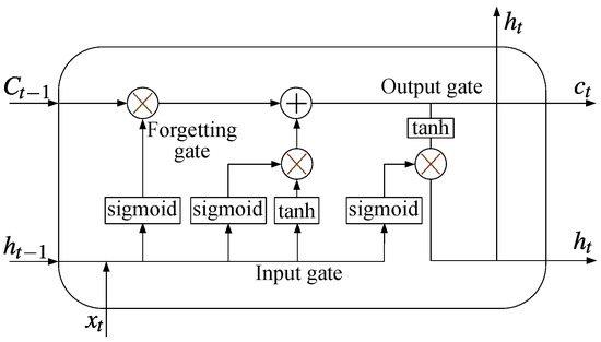
Figure 3.
Structure of LSTM.
The input gate controls the fraction of new input states and handles the information, which is represented as
The output gate produces results by merging the past input state with the current input state, which can be represented as
Among them, denotes the input vector at a given moment. The terms , , refer to the weight matrices and bias vectors for the forget gate, input gate, and output gate, respectively. refers to the stored value at a previous time step. The terms , , and correspond to the values of the forget, input, and output gates, respectively. represents the current state of the cell, while refers to the candidate state. The parameters and control the input gate, determining which information gets added to the candidate cell state.
3.3. Gated Recurrent Unit (GRU) Algorithm
The GRU, a type of Recurrent Neural Network (RNN) variant, was developed to address issues related to short-term memory and backpropagation gradients [31,32,33]. Unlike traditional RNNs, GRUs incorporate update and reset gates, which help integrate both current inputs and past information more effectively. The update gate works in tandem with the reset gate to manage both current and previous data. This structure allows a GRU to better retain long-term dependencies within time series data, thereby mitigating problems such as vanishing and exploding gradients. The internal structure of a GRU is displayed in Figure 4. The reset gate applies a Sigmoid function to convert the previous time step’s state into a value between 0 and 1. This value determines how much of the prior state should be kept, and it can be represented as follows:
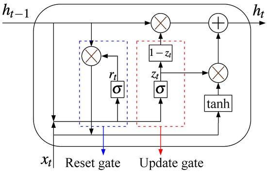
Figure 4.
Structure of GRU network.
The update gate employs a Sigmoid function to map the prior time information into the range , which determines how much of the previous information should be discarded. This process can be expressed as
In this context, and represent the weight and bias matrices for the reset gate, while denotes the input vector. The weight and bias matrices for the hidden layer are and , with as the candidate state of the hidden layer. Similarly, and are the weight and bias matrices for the update gate, and and are the inputs for the reset and update gates, respectively. The output value is represented by .
3.4. Proportional Integral Derivative (PID) Algorithms
The PID controller is an automatic feedback control mechanism that uses three components: proportional (P), integral (I), and derivative (D). The proportional component reacts to the current error between the actual and desired values, while the integral component accumulates the error over time to gradually correct persistent deviations. The derivative component predicts the future trend of the error by calculating its rate of change over time. The PID controller is included in the comparison, as outlined below:
The structure of the PID controller, as shown in Figure 5, is often used in industrial control systems to enhance system stability and performance.
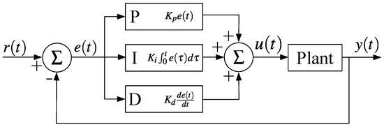
Figure 5.
Structure of PID.
3.5. Evaluation Criteria for Controller Performance
In this paper, the effectiveness of the proposed controller is evaluated based on two criteria: tracking precision and energy consumption of the system. To assess the tracking precision, the displacement error of the cylinder is evaluated using the root mean square error (RMSE) and the mean absolute error (MAE). The RMSE and MAE methods allow for a quantitative comparison of the proposed controller and other controllers, enabling informed conclusions about their effectiveness in achieving accurate and precise control over the cylinder’s displacement. The RMSE and MAE methods are defined as follows:
where n represents the number of displacement error samples .
4. Simulation and Experiment Results
To thoroughly assess the solution’s effectiveness, various scenarios were tested using both simulations and experiments.
In this paper, the correctness and efficiency of the proposed system are validated using data obtained from a test bench. A test bench was constructed to highlight the energy-saving potential and precise control of the boom cylinder position of the hybrid excavator equipped with the proposed system compared to the conventional system. The control algorithm, PSO-LSTM-GRU-PID, was combined with the ECMS for energy management, and the entire system was controlled via Simulink. Simultaneously, a simulation model for the proposed system, incorporating the PSO-LSTM-GRU-PID control algorithm and the ECMS, was developed and evaluated in Python 3.10.11. The lifting system of the proposed simulation model was validated through an experimental test on the test bench. The results from both the experimental system and the simulation model closely align, demonstrating the model’s accuracy, with simulation results only slightly deviating from real-world data.
4.1. Simulation Model Development
4.1.1. Simulation Model
A simulation model was developed using AMESim software version 2310, as illustrated in Figure 6, to evaluate the model’s controllability and confirm the energy savings of the proposed system.
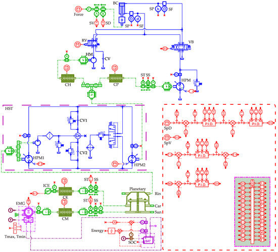
Figure 6.
AMESim model of the proposed system.
4.1.2. Comparison Simulation Results and Discussion
Figure 7 presents a comparison of the boom cylinder’s displacement and displacement error. Throughout the raising and lowering phases of the cylinder, the LSTM-GRU-PID and PSO-LSTM-GRU-PID controllers exhibit superior tracking performance compared to the PID controller. By optimizing the four hyperparameters in the LSTM-GRU-PID controller, the proposed PSO-based controller achieves both superior tracking accuracy and a quicker convergence rate. Furthermore, to maintain a fair comparison, the MAE and RMSE values for the three controllers are shown in Figure 8a,b. The results clearly show that the PSO-LSTM-GRU-PID controller consistently achieves a lower RMSE than the other two controllers, about and of those from LSTM-GRU-PID and PID controllers, and the MAE results follow a similar trend as the RMSE, with the proposed controller showing the lowest MAE value. This demonstrates that the system’s tracking accuracy has been enhanced through the optimization of the control coefficients.
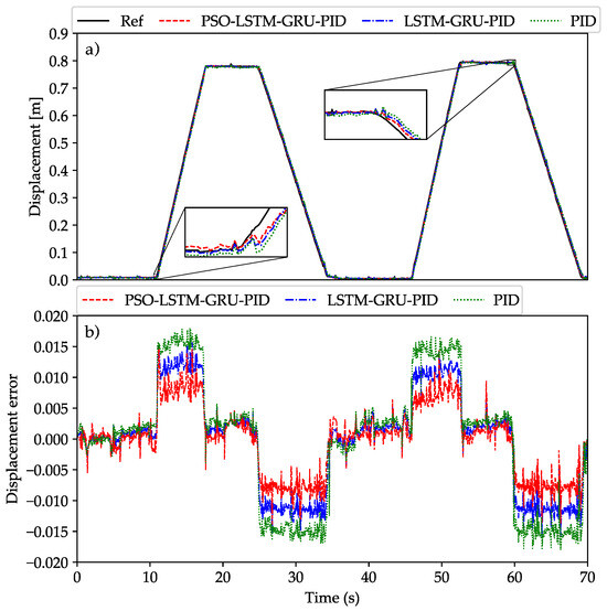
Figure 7.
Evaluation of the system’s tracking accuracy in the simulation model. (a) Displacement of the boom cylinder (b) Displacement error.
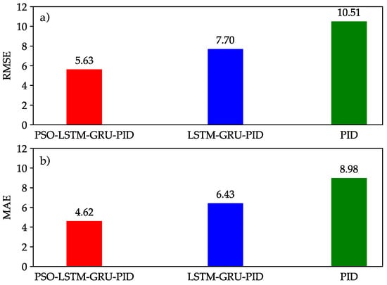
Figure 8.
The chart displays RMSE and MAE for the operating modes in the simulation. (a) RMSE (b) MAE.
Most of the time, the proposed controller always has better tracking precision. This advantage is achieved through the seamless coordination between the components in the system. Figure 9 represents the speed, torque, and energy consumption of the ICE. Besides tracking accuracy, energy consumption is a key factor in assessing the performance of the proposed controller. When conducting a detailed analysis of energy consumption for each individual mode, the PSO-LSTM-GRU-PID controller consumes 2.376 kJ less energy than the LSTM-GRU-PID controller and 8.85 kJ less than the PID controller. In summary, the proposed controller exhibits excellent energy efficiency for the system.
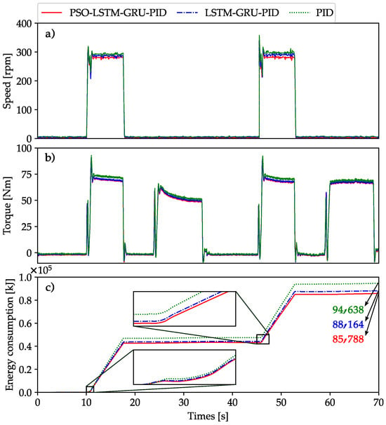
Figure 9.
Comparison of system performance in terms of speed (a), torque (b), and energy consumption (c) of the ICE based on simulation results.
In conclusion, the simulation results provide a thorough assessment of the PSO-LSTM-GRU-PID controller’s effectiveness within the proposed system. Despite the presence of complex noise, the controller maintains excellent tracking precision while achieving notable energy savings across four operating modes. Specifically, it reduces energy consumption by compared to the LSTM-GRU-PID controller and by relative to the PID controller.
Based on the comparison of algorithm running times, the PSO-LSTM-GRU-PID has the longest training time at 1975.72 s, followed by LSTM-GRU-PID at 1555.53 s, as shown in Table 2. The addition of PSO increases the training duration compared to the LSTM-GRU-PID combination. The PID algorithm, being a simpler controller, requires no training time. All three algorithms have the same testing time of 70 s, indicating that testing efficiency is consistent across them despite differences in training complexity.
Table 2.
Comparison of algorithm running times based on simulation results.
4.2. Experimental System
4.2.1. Experiment SETUP
A physical test bench was employed to validate the practical effectiveness of the PSO-LSTM-GRU-PID controller within the proposed system. Figure 10 presents the test bench, meticulously crafted to simulate the hydraulic boom excavator in a controlled lab environment. The controller was deployed on a computer running MATLAB/Simulink R2023a and operated through the Simulink Desktop Real-Time interface. Signals were sent to the electrical box via a PCI card, overseeing the operation of the ICE (1) and other components. A speed and a torque sensor were installed on the ICE shaft to gather data related to energy usage analysis. Additionally, a position sensor was installed on the cylinder to monitor tracking accuracy.
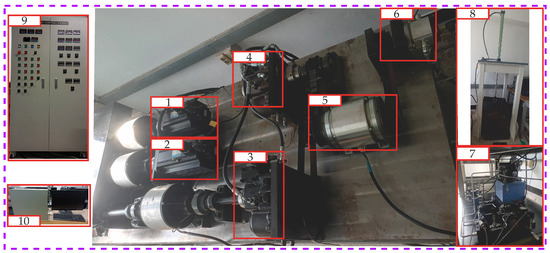
Figure 10.
The experimental test bench for the proposed boom system. (1) ICE, (2) EMG, (3) HST, (4) HPM, (5) double clutch, (6) HM, (7) hydraulic system, (8) load, (9) electrical box, (10) PC.
As in the simulation phase, a comparison of three controllers was conducted to highlight the benefits of the proposed controller for practical implementation in the system.
During the cylinder extraction, considering the efficiency map of the ICE reveals that efficiency is decided upon torque and speed as depicted in Figure 11.
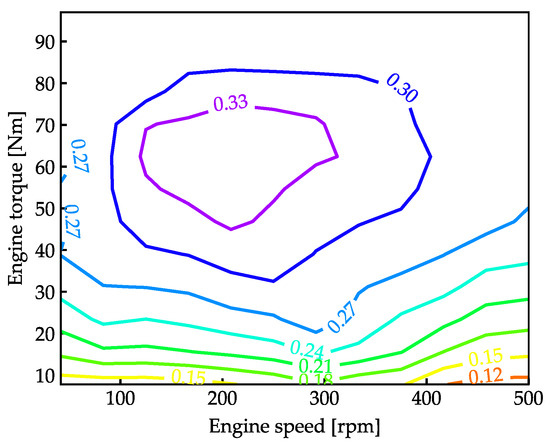
Figure 11.
Engine efficiency map.
A comprehensive Simulink model was developed using MATLAB software R2023a, as depicted in Figure 12, to implement advanced control algorithms and ensure precise control of a hydraulic cylinder. The model seamlessly integrates with the real-world system, not only validating the controllability of the proposed approach but also evaluating its practical performance, particularly in terms of energy efficiency. Within this Simulink environment, the dynamic behavior of the hydraulic system is meticulously emulated, allowing for detailed analysis and optimization of control strategies to achieve accurate cylinder positioning and enhanced energy savings, demonstrating the model’s capability to effectively manage both control precision and energy conservation.
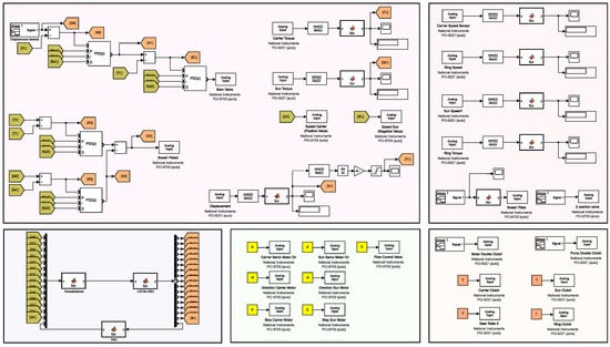
Figure 12.
Simulink model of the experiment setup of the proposed system.
Table 3 provides an overview of the algorithm parameters and characteristics used in this study, detailing the architecture of the LSTM-GRU model and its training process. It highlights key features like sequence length, activation functions, and the optimizer (Adam), whose learning rate is tuned by PSO. Additionally, PSO is used for hyperparameter optimization, aiming to minimize the MSE.
Table 3.
Algorithm parameters and characteristics.
4.2.2. Comparison Results and Discussion
The tracking position outcomes for the three controllers in the proposed system are presented in Figure 13 and Figure 14. Based on these results, the proposed controller outperforms both the PID and LSTM-GRU-PID controllers, maintaining a maximum error below 0.02 m, as illustrated in Figure 13. Moreover, the proposed controller demonstrates quicker response times and faster convergence across all modes (i.e., the processes of raising and lowering with different velocities and loads), benefiting from the optimized control parameters in the PSO-LSTM-GRU-PID system. This finding is further supported by Figure 14a,b, where the suggested controller consistently achieves the smallest RMSE and MAE values during the operation. The results clearly show that the PSO-LSTM-GRU-PID controller consistently achieves a lower RMSE than the other two controllers, about and of those from LSTM-GRU-PID and PID controllers.
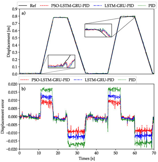
Figure 13.
Evaluation of the system’s tracking accuracy in the experimental platform. (a) Displacement of the boom cylinder (b) Displacement error.
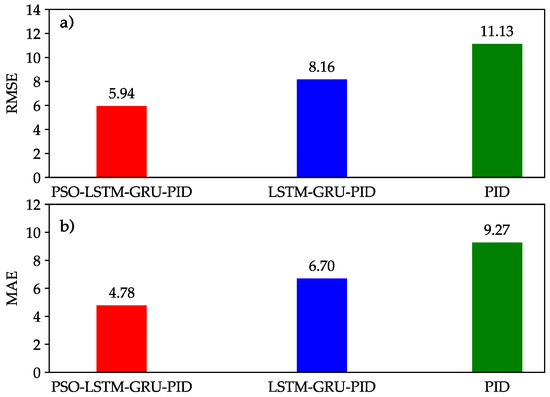
Figure 14.
The chart displays RMSE and MAE for the operating modes in the experiments. (a) RMSE (b) MAE.
From the speed and torque data, the efficiency of each working point can be determined by leveraging the ICE efficiency map illustrated in Figure 15. Using these data, the energy usage of the ICE is calculated.
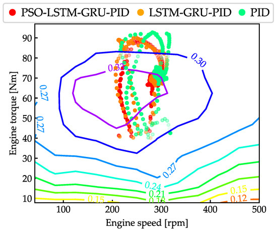
Figure 15.
Operational points for the ICE of proposed system.
Thanks to the advantages of the proposed controller, the ICE speed increases rapidly between 10.5 and 11 s, as depicted in Figure 16a, which leads to faster reaction time for the cylinder in this operation. The speed of the ICE reaches 280 rpm during this interval, enabling a faster reduction in displacement error.
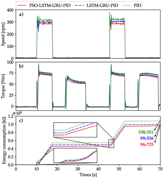
Figure 16.
Comparison of system performance in terms of speed (a), torque (b), and energy consumption (c) of the ICE based on experimental results.
The energy consumption comparison is illustrated in Figure 16c. The proposed system, utilizing the PSO-LSTM-GRU-PID controller, demonstrates lower energy usage across all four working modes, achieving energy savings of compared to the LSTM-GRU-PID controller and compared to the PID controller.
Based on the comparison of algorithm running times, the PSO-LSTM-GRU-PID has the longest training time at 2004.32 s, followed by LSTM-GRU-PID at 1584.24 s, as shown in Table 4. The addition of PSO increases the training duration compared to the LSTM-GRU-PID combination. The PID algorithm, being a simpler controller, requires no training time. All three algorithms have the same testing time of 70 s, indicating that testing efficiency is consistent across them despite differences in training complexity. In a MATLAB environment, the training times for these algorithms are expected to be similar to those observed in Python simulations, as the underlying computational processes and algorithmic structures are equivalent across both platforms.
Table 4.
Comparison of algorithm running times based on experimental results.
The results indicate that the proposed controller successfully mitigates disturbance factors such as system leakage, throttling loss, and noise while maintaining high tracking accuracy and energy efficiency within the system. Experimental validation confirms that the PSO-LSTM-GRU-PID controller performs efficiently in real-world applications, specifically in the boom excavator system.
5. Conclusions
In this study, we introduced the PSO-LSTM-GRU-PID control method to enhance tracking accuracy and energy efficiency in boom excavator systems. The following key highlights summarize our findings and contributions:
- Enhanced precision and stability: The LSTM-GRU-PID controller significantly improved the precision, stability, and response time of the boom excavator system, offering a more accurate control performance.
- Automated parameter optimization: The PSO method was utilized to automatically fine-tune four critical parameters of the LSTM-GRU-PID controller (GRU units, LSTM units, dropout rate, and learning rate), resulting in a robust and reliable performance even in the presence of external disturbances.
- Superior control in various conditions: The proposed control system demonstrated excellent control capabilities under different conditions, such as variations in cylinder velocity and load changes, validated through both simulation and experimental results.
- Energy efficiency and tracking improvements: Compared to traditional controllers, the system achieved better tracking and energy savings: 2.82% improvement in tracking accuracy over the LSTM-GRU-PID controller and 10.89% reduction in energy consumption compared to the PID controller.
Future work and directions: We aim to focus on further reducing the cylinder’s response time to enhance tracking accuracy in hydraulic excavators. Additionally, future research will explore methods for capturing and reusing gravitational potential energy to increase the system’s overall energy efficiency.
Author Contributions
V.-H.N. carried out the investigation and methodology, built and validated the model and the proposed algorithm through AMESim simulation and Python, set up the simulation, and wrote the original manuscript. T.C.D. supported the simulation setup and checked the manuscript. K.-K.A. was the supervisor providing funding and administrating the project, as well as reviewing and editing the manuscript. All authors have read and agreed to the published version of the manuscript.
Funding
This work was supported by “Regional Innovation Strategy (RIS)” through the National Research Foundation of Korea (NRF) funded by the Ministry of Education (MOE), South Korea (2021RIS-003), and by University of Economics Ho Chi Minh City, Vietnam.
Data Availability Statement
Data are contained within the article.
Conflicts of Interest
The authors declare no conflicts of interest.
Abbreviations
| HEs | Hydraulic excavators |
| HHEs | Hybrid hydraulic excavators |
| EERSs | Electric energy regeneration systems |
| HERSs | Hydraulic energy regeneration systems |
| ICE | Internal combustion engine |
| EMG | Electric motor/generator |
| BAT | Battery |
| HST | Hydrostatic transmission |
| HPM | Hydraulic pump/motor |
| HM | Hydraulic motor |
| EHCVP | Electrical hydraulic continually variable powertrain |
| EMS | Energy management strategy |
| ECMS | Equivalent consumption minimization strategy |
| A-ECMS | Adaptive equivalent consumption minimization strategy |
| SOC | State of charge |
| BC | Boom cylinder |
| VB | Control valve of boom cylinder |
| RV | Regeneration valve of boom cylinder |
| CV | Check valve |
| CE | Clutch of ICE |
| CM | Clutch of EMG |
| CP (DbC) | Clutch of HPM (double clutch) |
| CH (DbC) | Clutch of HM (double clutch) |
| Ring | Ring gear |
| Sun | Sun gear |
| ST | Sensor torque |
| SS | Sensor speed |
| SD | Sensor displacement |
| SV | Sensor velocity |
| PSO | Particle swarm optimization |
| LSTM | Long short-term memory |
| GRU | Gated recurrent unit |
| PID | Proportional integral derivative |
References
- Ding, R.; Zhang, J.; Xu, B.; Cheng, M.; Pan, M. Energy efficiency improvement of heavy-load mobile hydraulic manipulator with electronically tunable operating modes. Energy Convers. Manag. 2019, 188, 447–461. [Google Scholar] [CrossRef]
- Chen, M.; Zhao, D. The gravitational potential energy regeneration system with closed-circuit of boom of hydraulic excavator. Mech. Syst. Signal Process. 2017, 82, 178–192. [Google Scholar] [CrossRef]
- He, X.; Xiao, G.; Hu, B.; Tan, L.; Tang, H.; He, S.; He, Z. The applications of energy regeneration and conversion technologies based on hydraulic transmission systems: A review. Energy Convers. Manag. 2020, 205, 112413. [Google Scholar] [CrossRef]
- Lin, T.; Wang, Q.; Hu, B.; Gong, W. Development of hybrid powered hydraulic construction machinery. Autom. Constr. 2010, 19, 11–19. [Google Scholar] [CrossRef]
- Yang, C.; Zhou, L.; Wang, J.; Xu, T.; Yang, C.; Ye, G. Research on energy saving system of hydraulic excavator based on three-chamber accumulator. J. Energy Storage 2023, 72, 108571. [Google Scholar] [CrossRef]
- Zhang, W.; Wang, J.; Du, S.; Ma, H.; Zhao, W.; Li, H. Energy Management Strategies for Hybrid Construction Machinery: Evolution, Classification, Comparison and Future Trends. Energies 2019, 12, 2024. [Google Scholar] [CrossRef]
- Xia, L.; Quan, L.; Ge, L.; Hao, Y. Energy efficiency analysis of integrated drive and energy recuperation system for hydraulic excavator boom. Energy Convers. Manag. 2018, 156, 680–687. [Google Scholar] [CrossRef]
- Ho, T.H.; Le, T.D. Development and Evaluation of Energy-Saving Electro-Hydraulic Actuator. Actuators 2021, 10, 302. [Google Scholar] [CrossRef]
- Do, T.C.; Dinh, T.Q.; Yu, Y.; Ahn, K.K. Innovative powertrain and advanced energy management strategy for hybrid hydraulic excavators. Energy 2023, 282, 128951. [Google Scholar] [CrossRef]
- Han, J.; Wang, F.; Sun, C. Trajectory Tracking Control of a Manipulator Based on an Adaptive Neuro-Fuzzy Inference System. Appl. Sci. 2023, 13, 1046. [Google Scholar] [CrossRef]
- Nayak, N.; Das, S.R.; Panigrahi, T.K.; Das, H.; Nayak, S.R.; Singh, K.K.; Askar, S.S.; Abouhawwash, M. Overshoot Reduction Using Adaptive Neuro-Fuzzy Inference System for an Autonomous Underwater Vehicle. Mathematics 2023, 11, 1868. [Google Scholar] [CrossRef]
- Wang, X.; Abtahi, S.M.; Chahari, M.; Zhao, T. An Adaptive Neuro-Fuzzy Model for Attitude Estimation and Control of a 3 DOF System. Mathematics 2022, 10, 976. [Google Scholar] [CrossRef]
- Song, H.; Li, G.; Li, Z.; Xiong, X. Trajectory Control Strategy and System Modeling of Load-Sensitive Hydraulic Excavator. Machines 2023, 11, 10. [Google Scholar] [CrossRef]
- Nguyen, T.H.; Do, T.C.; Phan, V.D.; Ahn, K.K. Working Performance Improvement of a Novel Independent Metering Valve System by Using a Neural Network-Fractional Order-Proportional-Integral-Derivative Controller. Mathematics 2023, 11, 4819. [Google Scholar] [CrossRef]
- Ahmad, Z.; Li, J.; Mahmood, T. Adaptive Hyperparameter Fine-Tuning for Boosting the Robustness and Quality of the Particle Swarm Optimization Algorithm for Non-Linear RBF Neural Network Modelling and Its Applications. Mathematics 2023, 11, 242. [Google Scholar] [CrossRef]
- Xuanyu, L.; Mengting, J.; Wenshuai, Z.; Yudong, W. Intelligent real-time prediction for shield machine position on the basis of BWO-LSTM-GRU. Eng. Res. Express 2024, 6, 015105. [Google Scholar] [CrossRef]
- Han, M.; Fan, J.; Wang, J. A Dynamic Feedforward Neural Network Based on Gaussian Particle Swarm Optimization and its Application for Predictive Control. IEEE Trans. Neural Netw. 2011, 22, 1457–1468. [Google Scholar] [CrossRef]
- Gao, W.; Peng, X.; Guo, W.; Li, D. A Dual-Competition-Based Particle Swarm Optimizer for Large-Scale Optimization. Mathematics 2024, 12, 1738. [Google Scholar] [CrossRef]
- Huang, X.; Xu, R.; Yu, W.; Wu, S. Evaluation and Analysis of Heuristic Intelligent Optimization Algorithms for PSO, WDO, GWO and OOBO. Mathematics 2023, 11, 4531. [Google Scholar] [CrossRef]
- Oladejo, S.O.; Ekwe, S.O.; Mirjalili, S. The Hiking Optimization Algorithm: A novel human-based metaheuristic approach. Knowl.-Based Syst. 2024, 296, 111880. [Google Scholar] [CrossRef]
- Khunkitti, S.; Premrudeepreechacharn, S.; Siritaratiwat, A. A Two-Archive Harris Hawk Optimization for Solving Many-Objective Optimal Power Flow Problems. IEEE Access 2023, 11, 134557–134574. [Google Scholar] [CrossRef]
- Wang, X.; Snášel, V.; Mirjalili, S.; Pan, J.S.; Kong, L.; Shehadeh, H.A. Artificial Protozoa Optimizer (APO): A novel bio-inspired metaheuristic algorithm for engineering optimization. Knowl.-Based Syst. 2024, 295, 111737. [Google Scholar] [CrossRef]
- Nguyen, V.H.; Do, T.C.; Ahn, K.K. Investigation and Optimization of Energy Consumption for Hybrid Hydraulic Excavator with an Innovative Powertrain. Actuators 2023, 12, 382. [Google Scholar] [CrossRef]
- Hu, B.; Li, J. A Deployment-Efficient Energy Management Strategy for Connected Hybrid Electric Vehicle Based on Offline Reinforcement Learning. IEEE Trans. Ind. Electron. 2022, 69, 9644–9654. [Google Scholar] [CrossRef]
- Tian, X.; Cai, Y.; Sun, X.; Zhu, Z.; Xu, Y. An adaptive ECMS with driving style recognition for energy optimization of parallel hybrid electric buses. Energy 2019, 189, 116151. [Google Scholar] [CrossRef]
- Wei, C.; Chen, Y.; Sun, X.; Zhang, Y. Optimal Equivalent Consumption Minimization Strategy for Plug-In Hybrid Electric Vehicle with Improved Genetic Algorithm. SAE Int. J. Electrified Veh. 2020, 9, 143–154. [Google Scholar] [CrossRef]
- Liu, X.; Qin, D.; Wang, S. Minimum Energy Management Strategy of Equivalent Fuel Consumption of Hybrid Electric Vehicle Based on Improved Global Optimization Equivalent Factor. Energies 2019, 12, 2076. [Google Scholar] [CrossRef]
- Zhou, D.; Al-Durra, A.; Matraji, I.; Ravey, A.; Gao, F. Online Energy Management Strategy of Fuel Cell Hybrid Electric Vehicles: A Fractional-Order Extremum Seeking Method. IEEE Trans. Ind. Electron. 2018, 65, 6787–6799. [Google Scholar] [CrossRef]
- Yang, C.; Du, X.; Wang, W.; Yuan, L.; Yang, L. Variable optimization domain-based cooperative energy management strategy for connected plug-in hybrid electric vehicles. Energy 2024, 290, 130206. [Google Scholar] [CrossRef]
- Hochreiter, S.; Schmidhuber, J. Long Short-Term Memory. Neural Comput. 1997, 9, 1735–1780. [Google Scholar] [CrossRef]
- Ibrahim, M.S.; Abbas, W.; Waseem, M.; Lu, C.; Lee, H.H.; Fan, J.; Loo, K.H. Long-Term Lifetime Prediction of Power MOSFET Devices Based on LSTM and GRU Algorithms. Mathematics 2023, 11, 3283. [Google Scholar] [CrossRef]
- Kim, G.I.; Jang, B. Petroleum Price Prediction with CNN-LSTM and CNN-GRU Using Skip-Connection. Mathematics 2023, 11, 547. [Google Scholar] [CrossRef]
- Tjandra, A.; Sakti, S.; Manurung, R.; Adriani, M.; Nakamura, S. Gated Recurrent Neural Tensor Network. In Proceedings of the 2016 International Joint Conference on Neural Networks (IJCNN), Vancouver, BC, Canada, 24–29 July 2016; pp. 448–455. [Google Scholar] [CrossRef]
Disclaimer/Publisher’s Note: The statements, opinions and data contained in all publications are solely those of the individual author(s) and contributor(s) and not of MDPI and/or the editor(s). MDPI and/or the editor(s) disclaim responsibility for any injury to people or property resulting from any ideas, methods, instructions or products referred to in the content. |
© 2024 by the authors. Licensee MDPI, Basel, Switzerland. This article is an open access article distributed under the terms and conditions of the Creative Commons Attribution (CC BY) license (https://creativecommons.org/licenses/by/4.0/).