Abstract
In this paper, we present an electric field analysis for the optimal structural design of lightning rods for high performance with a charge transfer system (CTS). In the case of a conventional rod that is produced with an empirical design and structure without quantitative data because the design is structurally very simple, only the materials and radius of curvature of the lightning rod to concentrate the electric field at the tip part of the rod are considered. Recently, the development of new types of lightning rods, such as early streamer emission (ESE) and charge transfer system (CTS), has been introduced through simulation analysis and experiments, but detailed specifications and information about the optimal design and structure have not been fully reported. In this paper, we performed an electric field analysis of the structures and materials for the optimal structural design of lightning rods with a function of CTS through computer software analysis with consideration for the radius of curvature, the size of corona ring, and optimal position (X-axis and Y-axis) of the floating electrode. For optimal structural design of lightning rods based on electric field analysis, we used a source of lightning voltage with 1.2/50 µs based on a double exponential equation. The results revealed that the electric field on the relaxation part decreases as the radius of curvature and corona ring increases. For the radius of curvature, the electric field first decreases and then increases with increasing radius of curvature and reaches a minimum at 7 mm and a maximum above 8 mm. For the case of the corona ring, the electric field decreases with increasing corona ring, and the optimal size of the corona ring was selected as 4 mm; the size of the 4 mm corona ring uniformly formed the electric field both at the tip part of the ground current collector and the corona ring. For the electric field concentration part, we found that the optimal X-axis position of the floating electrode and the Y-axis position between the ionizer conductor and floating electrode are 7 mm and 0.1 mm, respectively. These simulation results in this paper are expected to provide useful information for the design of optimized CTS-type lightning rods.
Keywords:
lightning rod protection; charge transfer system (CTS); electric field analysis; numerical analysis; optimal design; finite element method; corona discharge; air insulation MSC:
65K10
1. Introduction
Direct or indirect lightning strikes cause power outages, forest fires, and other damages to various electronic systems as well as infrastructure, with associated costs of billions of euros each year [,]. Despite technological advances, lightning protection rods still rely on the nearly 300-year-old basic concept of the lightning rod as invented by Benjamin Franklin [].
The purpose of a lightning rod is to induce lightning strikes at a particular point with a very sharp tip and low-impedance paths for concentrating the local electric field from direct or indirect lightning strikes. In the case of conventional Franklin lightning rods, the structure and design are very simple; in other words, only the materials, radius of curvature, installation position, height and quantity needed to induce a high local electric field at the tip part of the Franklin rod after lightning strikes need to be considered. However, recently the structure and design of lightning rods have been advanced and diversified, and various types of lightning rods have been developed and introduced, such as early streamer emission (ESE) and charge transfer system (CTS), to effectively protect facilities from indirect or direct lightning strikes [,,]. In other words, to ensure optimal performance, quantitative analysis of the structures and materials of various types of lightning rods is required. However, studies do not report detailed specifications and information on the structures and materials utilized.
For this reason, a lot of work has recently been devoted to improving lightning rods based on the results of simulation analysis and experimentation methods that quantitatively optimize the performance of lightning rods. Dong-Jin Kim et al. [] suggested the HEC (Hybrid ESE Conductor) method, which mixes a horizontal conductor and an ESE lightning rod. Their results revealed that the starting point of a corona discharge current is low, and HEC is efficient for lightning protection compared with other methods based on experiment and simulation analysis. Vernon Cooray and Marley Becerra et al. [,] investigated the early streamer emission-enhanced ionizing air terminal and multi-points discharge system and conceptual future methods of lightning protection; the ESE lightning rod proposed in NF C 17-102 was compared to the conventional Franklin rods proposed in IEC 62305 using simulation analysis under laboratory conditions. Myung-Ki Baek et al. [] presented a numerical analysis method and experimental results for the discharge characteristic associated with the presence of a floating conductor with consideration of space charge on the surface of the floating electrode. The results revealed that the floating conductor can generate more electrons than other discharge systems without the floating electrode and that the corona discharge can be controlled using a floating conductor. Bok-hee Lee et al. [,] have introduced simulation analysis and experimentation for the validation of the CTS-type lightning rods. They introduced a new type of CTS lightning rod consisting of a floating electrode, 250 brushes, and a cylindrical conducting body. Their results obtained by experiment and simulation analysis showed the CTS-type lightning rods significantly decreased electric field intensification, which reduced the probability of direct lightning strikes. Thomas Produit et al. [] suggested a new approach for diverting lightning strikes: the laser lightning rod. For experiment and validation of the laser’s ability to initiate upward discharge from the tip of a lightning rod, the laser experiment at Säntis Tower was conducted. The results revealed that lasers would allow the protection of industrial sites, including chemical and nuclear power plants, and that creating protected corridors along runways would reduce breaks in airport operations during thunderstorms. However, in the aforementioned studies, a lot of them have only focused on the technology as well as the modification of the structure and shape. In other words, the detailed specifications and information about the optimal design and structure of lightning rods for high performance were not fully reported quantitatively.
From this perspective, the scientific aim of our research work is to investigate the electric potential and electric field distribution for the optimal design of lightning rods that have a charge transfer system (CTS) using a finite element method (FEM). In CTS-type lightning rods, the most important factors for optimal design are divided into two parts: the electric field concentration part and the electric field relaxation part. The optimal design of CTS-type lightning rods in two parts could be to create a non-uniform electric field with a large electric field enhancement, which can delay the upward streamer by generating a corona discharge in the air insulation system [,].
In this paper, there are two important parts needed to obtain an optimal design of CTS-type lightning rods. For the electric field relaxation part, we considered the variables of radius of curvature and corona ring size. To maximize the electric field concentration between the ionizer conductor and floating electrode, the positions of the X-axis and Y-axis were varied.
In this paper, Section 1 describes the introduction of the research work, Section 2 presents a model for electric field analysis and a detailed description of the analysis approach, Section 3 describes the results and discussion, and Section 4 presents the final conclusions and future directions of the research in this field. These simulation results are expected to offer useful information for optimizing the design of CTS-type lightning rods as well as lightning rods of other types.
2. Modeling for Electric Field Analysis
The optimized design for CTS-type lightning rods has focused on electric field distribution under lightning impulse voltage using an FEA software package. The basic equations used to calculate the electric field are Maxwell’s equations [], as follows:
The general expression of Poisson’s equation for electric field analysis from the above three Equations (1)–(3) is as follows []:
where is the relative permittivity of each material and E is the electric field. In this paper, space charge is negligible such that , i.e.,
Calculation of current density depending on time variation can be expressed as a current continuity equation, and the relationship between current density and bulk charge density satisfies the current continuity equation, as follows:
by substituting Formula (4) into Equation (5), the relationship between current density and field strength can be established.
if the current density conforms to Ohm’s Law:
where J is the current density, and it can be calculated following Equation (6) from Equations (5)–(7) using Ohm’s law as follows:
where is the electrical conductivity of each material, and the electric field is determined by the conductivity from Equation (8).
By substituting Equation (8) into Equation (5), the current continuity equation can be expressed as Equations (9) and (10) as follows:
Since the electric field is the result of the spatial differentiation of the electric potential, it can be expressed as follows:
Table 1 describes the significance of various abbreviations and acronyms used throughout the paper.

Table 1.
Abbreviations and acronyms used in this paper.
Figure 1 shows computer-aided numerical model geometry in COMSOL Multiphysics. In order to perform the electric field analysis of the CTS-type lightning rod under lightning impulse voltage, it is necessary to understand the structure of the model and the type of materials. The CTS-type lightning rod consists of not only copper and aluminum conductors but also ionizer conductors and insulating support structures such as epoxy resin, as shown in Figure 1. Equations (5), (8) and (11) are applied to all areas of the simulation model as shown in Figure 1. In addition, the zero charge node adds the condition that there is zero charge on the boundary . This is the default boundary condition for exterior boundaries. At interior boundaries, it means that no displacement field can penetrate the boundary and that the electric potential is discontinuous across the boundary. The boundary condition for V in Figure 1 is applied to the ground and CTS-type lightning rod as , while the electric potential considers that the potential voltage is 300 kV (standard lightning impulse voltage is applied until 1.2 . The air space between the tip part of the ground current collector and the opposite conductor is 300 mm.
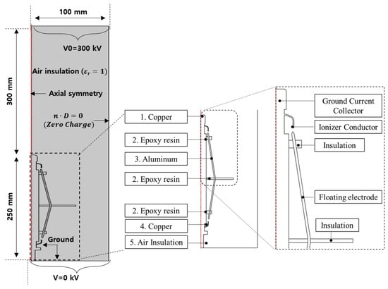
Figure 1.
Computer-aided design representation of the numerical model geometry.
The following Table 2 describes the name and function of the main components used throughout the paper [,].
Table 2.
Name and function of the main components of a CTS-type lightning rod.
Figure 2 shows the main two parts of this simulation: one part is electric field relaxation, and another part is electric field concentration. The main concept of the CTS lightning rod is to form a non-uniform electric field with a large electric field enhancement at the point of the electric field concentration part to delay the upward streamer. However, the tip part of the ground current collector suppresses the upward streamer through electric field relaxation.
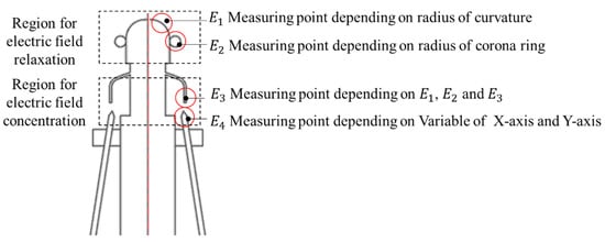
Figure 2.
Main measuring points (E1, E2: part for electric field relaxation; E3, E4: part for electric field concentration)
3. Results and Discussion
3.1. Electric Field Relaxation Part
Figure 3 shows the results of the electric field distribution (contour) and electric potential (solid line) depending on the radius of curvature of the tip part of the grounding current collector in air insulation under 300 kV impulse voltage. The is a maximum electric field at the tip part of the grounding current collector, is the decrease rate (%) of the electric field compared with the reference model (2 mm). To reduce the electric field on the relaxation part, the radius of curvature was changed from 2 mm to 8 mm. The electric field decreases with increasing radius of curvature and reaches a minimum at 7 mm (: 4.88 kV/mm, : −23%), and then the electric field shows an increasing trend at 8 mm (5.21 kV/mm, : −17%), as shown in Figure 4. The electric potential also widens the contour gap with increasing radius of curvature; the electric potential distribution at 8 mm curvature radius is formed in the vicinity of the tip part of the ground current collector as dense contour lines.
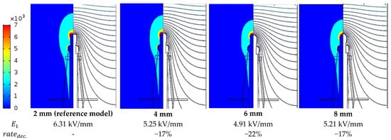
Figure 3.
Electric field (contour) and electric potential distribution (solid line) based on the radius of curvature [mm] under lightning impulse voltage.
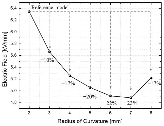
Figure 4.
Electric field level based on the radius of curvature.
The reason for the increased electric field at 8 mm radius of curvature is that the tip part of the grounding current collector formed a complete spherical shape at 8 mm radius of curvature, and the electric field was concentrated in the vicinity of the sphere tip part. From the above results, we selected the optimal curvature radius as 7 mm in this simulation model.
Figure 5 shows the electric field and electric potential distribution depending on the size of the corona ring. To reduce the electric field concentration, the size of the corona ring was changed from 2 mm to 15 mm. Electric field and electric potential were measured at three points (, and ) to select the optimal design criteria. The And In Figure 5 are the electric field decrease rates at points and , respectively, compared to the model without the corona ring.
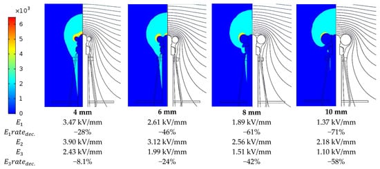
Figure 5.
Electric field (contour) and electric potential distribution (solid line) depending on the size of the corona ring [mm] under lightning impulse voltage.
The results revealed that the electric field at both the tip part of the ground current collector and the corona ring part decreases with increasing the size of the corona ring. In other words, it is found that the corona ring with a large radius of curvature has a definite effect on the electric field relaxation of the tip part compared with the model without a corona ring. However, in order to design a CTS-type lightning rod, the following two points should be considered.
(1) There should be uniform electric field formation in both the corona ring () and the tip part of the grounding current collector ().
(2) There should be no reduction in the electric field of the ionizer conductor () due to the increase in the corona ring size.
As shown in Figure 6, the electric field of the part is relaxed, and the electric field of the part is also relaxed at the same time as the size of the corona ring increases.
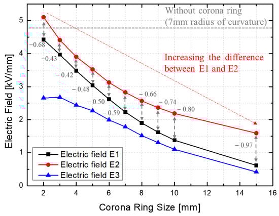
Figure 6.
Electric field level depending on the size of the corona ring compared with that without a corona ring.
Firstly, the difference between and was calculated and compared according to the corona ring size to select the corona ring size where the electric field difference between the corona ring part and the tip part of the grounding current collector was the minimum. The minimum difference between and depending on corona ring size was 4 mm, as shown in Figure 6. On the other hand, as the corona ring size increases, it might be possible that the electric field concentration occurs at the corona ring part, and it could be the starting point of early corona discharge inception under a high electric field.
Secondly, the electric field of is higher than that of others at the 3 mm corona ring, compared to the 3 mm corona ring, the size with the lowest were 2 mm and 4 mm. From the above results, we selected an optimal design that satisfies two conditions; the most reasonable design was the 4 mm corona ring.
3.2. Local Electric Field Concentration Part
Figure 7 shows the locations of the variable Y-axis and X-axis for simulation. In this Section 3.2, we have focused on electric field concentration, which is different from the results of Section 3.1’s electric field relaxation. The reference X-axis and Y-axis are 3 mm and 6 mm, respectively. In the case of the Y-axis, the simulation analysis was conducted by changing from 0.05 mm to 5 mm based on the reference model. The X-axis was also changed from 4 mm to 9 mm. The results revealed that the electric field increases with a decreasing air space by adjusting the Y-axis position of the floating electrode, as shown in Figure 8. The electric field strength at 0.1 mm of air space was higher than that of the other results for air space (mm). In other words, when the air space is above 1 mm, the electric field decreases by 30% compared to the 0.1 mm air space. The discussion on electric field distribution according to variable air space has been discussed by introducing the electron mean free path (MFP) theory in our previous research work []. If the air space is too far, the generated free electron could not excite another free electron for the electron avalanche between the ionizer conductor and grounding current collector. In other words, the first free electron cannot play a role as the seed of the secondary and tertiary electron avalanches []. In contrast, if the floating electrode is located near the ionizer conductor, the positive and negative charges are equally induced on the ionizer conductor and the floating electrode, and then the local electric field strength near them increases. This electric field concentration can cause the ionization process of the surrounding air insulation, and the corona discharge could have a different starting point at the electric field concentration part than at other parts [].
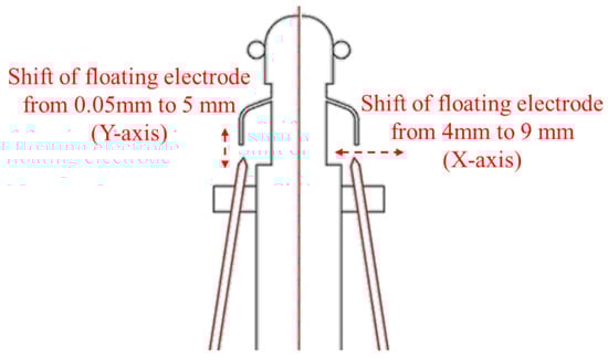
Figure 7.
Locations of X-axis and Y-axis for simulation analysis.
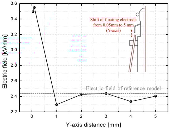
Figure 8.
Electric field results according to different Y-axis distances.
For the results of the variable X-axis as shown in Figure 9, element design was performed to increase the maximum electric field value by adjusting the X-axis position of the floating electrode. As a result, it is found that the high electric field distribution is formed at positions where the ionizer conductor and the floating electrode tip part coincide with each other. In addition, the distance of the electric potential line was densely formed at 7 mm on the X-axis model. In the case of a 7 mm X-axis, the maximum electric field value was 4.72 kV/mm, and the electric field value gradually decreased when moved away by 1 mm from the 7 mm X-axis. In our work, it is possible to reduce the electric field strength of the tip part of the grounding current collector by introducing the optimum design of curvature radius and corona ring. By introducing the optimal distance of X-axis and Y-axis, a high local electric field can be formed between the ionizer conductor and the floating electrode.
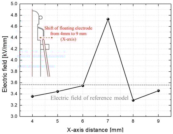
Figure 9.
Electric field results according to different X-axis distances.
From the above results, if the maximum electric field distribution is formed at the electric field concentration part rather than the tip part of the ground current collector, the concentration part could be causing the very first ionization and the starting point of early corona discharge inception under a high electric field as a possibility.
However, further experimental research is needed for validation of the above simulation research on the optimal design of CTS-type lightning rods in terms of electric potential and electric field distribution. Also, consideration of the temperature parameter is needed. The characteristics of conductivity materials are dependent on temperature variation by concentrated local electric field distribution.
4. Conclusions
Some researchers have focused more on the performance improvement of lightning rods according to modifications of the structure and shape than the optimal design and performance improvement based on quantitative data. For the aforementioned reason, it is not possible to obtain a detailed rationale for the location and size of each component. This research work has focused on the optimal design of CTS-type lightning rods for high performance. To investigate the optimal structure design, the following four factors are considered:
- (1)
- Radius of curvature (electric field relaxation)
- (2)
- Corona ring size (electric field relaxation)
- (3)
- The position of the floating electrode in the direction of the X-axis (electric field concentration)
- (4)
- The position of the floating electrode in the direction of the Y-axis (electric field concentration)
The results for electric field relaxation revealed that the electric field decreases with increasing radius of curvature and reaches a minimum at 7 mm, with an increasing trend above 8 mm. In addition, electric potential distribution also widens the contour gap with increasing radius of curvature at 7 mm. From the above results, we selected an optimized radius of curvature of 7 mm.
For the optimized size of the corona ring, the electric field of both parts (the tip part of the ground current collector and the corona ring part) decreases with increasing the size of the corona ring. We found that the optimized size of the corona ring was 4 mm due to the following two factors:
- (1)
- Uniform electric field formation, both at the corona ring and tip part of the grounding current collector.
- (2)
- The reduction in the electric field of the ionizer conductor due to the increase in corona ring size.
The optimized position of the floating electrode in the direction of the X-axis and Y-axis was 7 mm and 0.1 mm, respectively. If it is possible to locate the floating electrode near the ionizer conductor, the positive and negative charges are equally induced on the ionizer conductor and a floating electrode, and then the local electric field strength near them increases. In addition, this electric field concentration can cause the ionization of the surrounding air insulation, and the corona discharge could have a different starting point at the electric field concentration part than other parts.
For further work, experiments on the optimized design of a CTS-type lightning rod under standard lightning impulse voltage should be performed while considering neighboring grounded objects. Besides, a comparison with experimental and simulation results should be performed. For further computational work, some parameters such as electron mobility, positive and negative ion mobility under high electric field distribution, temperature, and melting of the electrode as a result of a local heat source from a lightning strike should be considered. A comparison between a conventional lighting rod and a CTS-type lightning rod should be performed to verify the performance of the CTS-type lightning rod.
Author Contributions
K.-H.J., contributed to conceptualization, methodology, analysis, and writing. S.-W.S., contributed to validation, formal analysis, data curation, and visualization. D.-J.K., contributed to reviewing and editing. All authors have read and agreed to the published version of the manuscript.
Funding
This study was supported by the Korea Institute of Energy Technology Evaluation and Planning (KETEP), and we were granted financial resources from the Ministry of Trade, Industry and Energy (MOTIE) (20212020800090, Development and Demonstration of Energy-Efficiency Enhanced Technology for Temperature-Controlled Transportation and Logistics Center).
Institutional Review Board Statement
Not applicable.
Informed Consent Statement
Not applicable.
Data Availability Statement
Not applicable.
Conflicts of Interest
The authors declare no conflict of interest.
References
- Lightning Costs and Losses from Attributed Sources, Lightning Costs and Losses from Attributed Sources—National Lightning Safety Institute. 2020. Available online: https://lightningelectricity.com/ (accessed on 22 March 2020).
- Facts + Statistics: Lightning. 2022. Available online: https://www.iii.org/fact-statistic/facts-statistics-lightning (accessed on 22 March 2020).
- History.com Editors. Benjamin Franklin. A&E Television Networks, 2022 (Last Updated). Available online: https://www.history.com/topics/american-revolution/benjamin-franklin (accessed on 22 March 2022).
- Kim, H.-G.; Lee, K.-S. The Change of Lightning Air Terminal and Trend of the World. In Proceedings of the International Symposium on High Voltage Engineering, Hannover, Germany, 22–26 August 2011. [Google Scholar]
- Cooray, V. The Similarity of the Action of Franklin and ESE Lightning Rods under Natural Conditions. Atmosphere 2018, 9, 225. [Google Scholar] [CrossRef]
- Cooray, V. Non-Conventional Lightning Protection System. In Proceedings of the 30th International Conference on Lightning Protection (ICLP), Cagliari, Italy, 13–17 September 2010. [Google Scholar]
- Kim, D.-J. A Study on the HEC (Hybrid ESE Conductor) Method for Lightning Protection of Buildings. Trans. Korean Inst. Electr. Eng. 2008, 57, 2. [Google Scholar]
- Mladen, B. Early Streamer Emission Vs Conventional Lightning Protection Systems. B&H Electr. Eng. 2019, 13, 24–34. [Google Scholar]
- Becerra, M.; Cooray, V. The Early Streamer Emission Principle Does Not Work Under Natural Lightning. In Proceedings of the International Symposium on Lightning Protection, Foz do Iguaçu, Brazil, 26–30 November 2007. [Google Scholar]
- Baek, M.K.; Chung, Y.K.; Park, I.H. Experiment and Analysis for Effect of Floating Conductor on Electric Discharge Characteristic. IEEE Trans. Magn. 2013, 49, 5. [Google Scholar] [CrossRef]
- Lee, B.-H. Effect of the Corona Shield of the OMNI Bipolar Conventional Air Terminals. In Proceedings of the 2016 International Conference on ElectroMagnetic Interference & Compatibility (INCEMIC), Bengaluru, India, 8–9 December 2016. [Google Scholar]
- Lee, B.-H. Analysis and Test on Electric Field Concentration Effect of Bipolar Conventional Air Terminal. In Proceedings of the International Conference on Lightning Protection (ICLP), Shanghai, China, 11–18 October 2014. [Google Scholar]
- Produit, T. The Laser Lightning Rod Project. Eur. Phys. J. Appl. Phys. 2020, 92, 30501. [Google Scholar] [CrossRef]
- Jang, K.-H. Corona Discharge Behaviors with Presence of Floating Electrode in Air Insulation using Numerical Model Analysis. J. Mater. Sci. Manuf. Res. 2023, 4, 1–4. [Google Scholar] [CrossRef]
- Jang, K.-H. Numerical Simulation Analysis on Non-Conventional Lightning Protection System. In Proceedings of the IEEE 4th Eurasia Conference on IOT, Communication and Engineering (ECICE), Yunlin, Taiwan, 28–30 October 2022. [Google Scholar]
- Jackson, J.D. Classical Electrodynamics, 3rd ed.; Wiley: New York, NY, USA, 1999. [Google Scholar]
- Benguesmia, H.; M’ziou, N. Simulation of the Potential and Electric Field Distribution on High Voltage Insulator using the Finite Element Method. Diagnostyka 2018, 19, 2. [Google Scholar] [CrossRef]
- Shi, Y.; Xie, G.; Wang, Q. Simulation Analysis and Calculation of Electric Field Distribution Characteristics of UHV Wall Bushing. In Proceedings of the 4th International Conference on Electrical Engineering and Green Energy CEEGE, Munich, Germany, 10–13 June 2021. [Google Scholar]
- Liao, L.; Xue, T.; Xiong, J.; Lu, B. Research on the Influence of the Relative Permittivity of the Reinforced Insulation of the Cable Intermediate Joint on the Electric Field Intensity. J. Phys. Conf. Ser. 2021, 1815, 012037. [Google Scholar] [CrossRef]
- Jang, K.-H.; Seo, S.-W.; Kim, D.-J. Electric Field Analysis on the Corona Discharge Phenomenon according to the Variable Air Space between the Ionizer and Ground Current Collector. Appl. Syst. Innov. 2023, 6, 10. [Google Scholar] [CrossRef]
- Lee, J.-H. Local Electric Field Analysis for Evaluation of Charge Transfer System Using Sequential Subwindow Technique. IEEE Trans. Magn. 2004, 40, 2. [Google Scholar] [CrossRef]
Disclaimer/Publisher’s Note: The statements, opinions and data contained in all publications are solely those of the individual author(s) and contributor(s) and not of MDPI and/or the editor(s). MDPI and/or the editor(s) disclaim responsibility for any injury to people or property resulting from any ideas, methods, instructions or products referred to in the content. |
© 2023 by the authors. Licensee MDPI, Basel, Switzerland. This article is an open access article distributed under the terms and conditions of the Creative Commons Attribution (CC BY) license (https://creativecommons.org/licenses/by/4.0/).