
Mitigation of Circulating Bearing Current in Induction Motor Drive Using Modified ANN Based MRAS for Traction Application

 ,
,  , , ,
, , , 
Abstract
1. Introduction
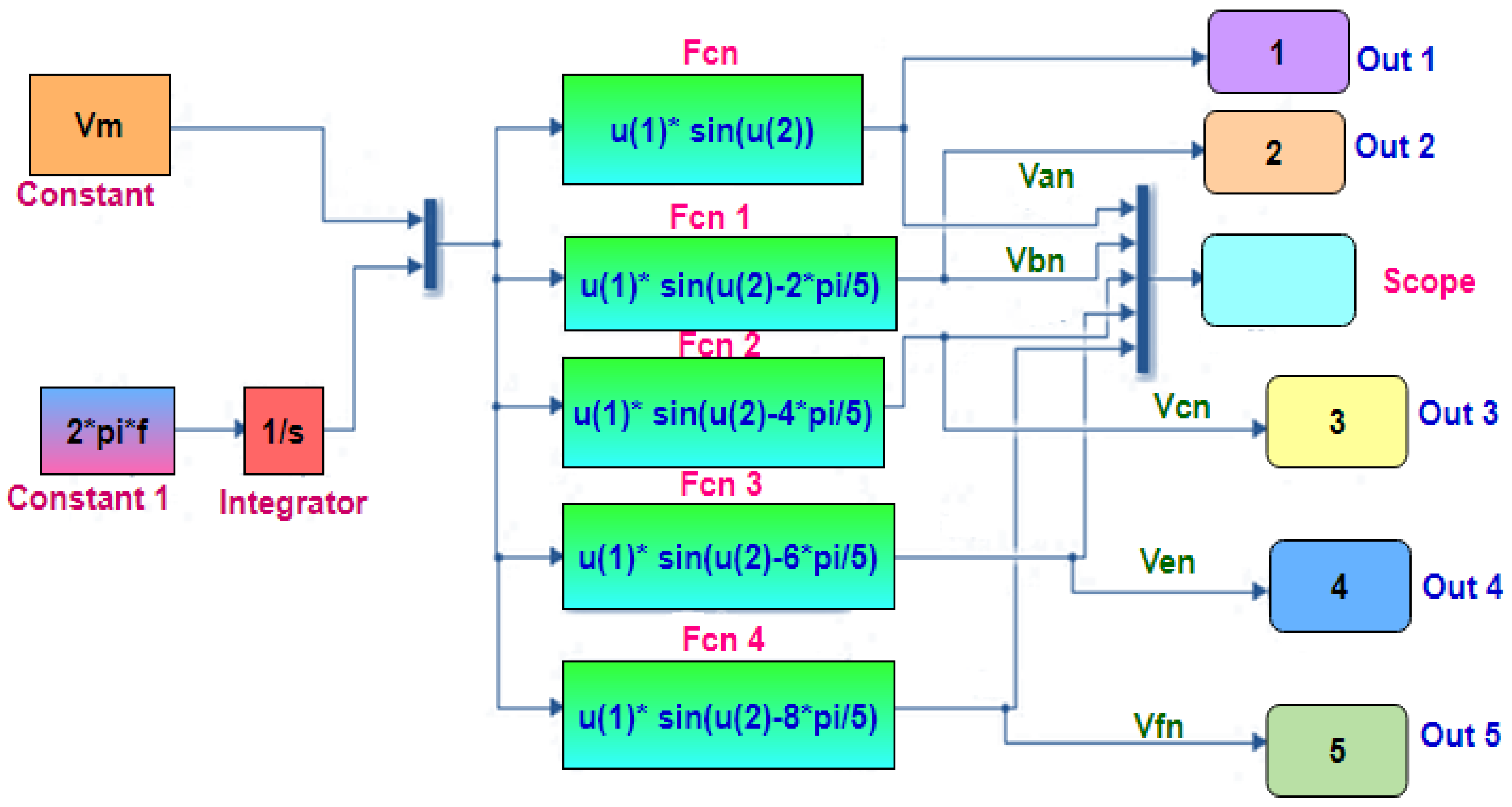
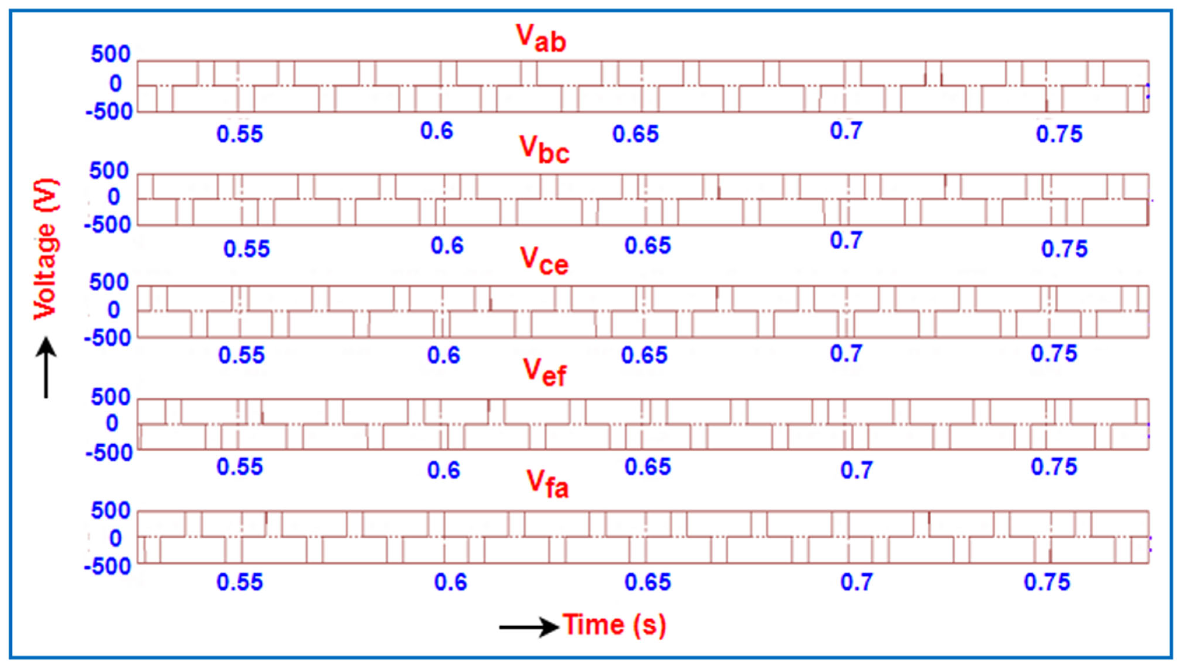
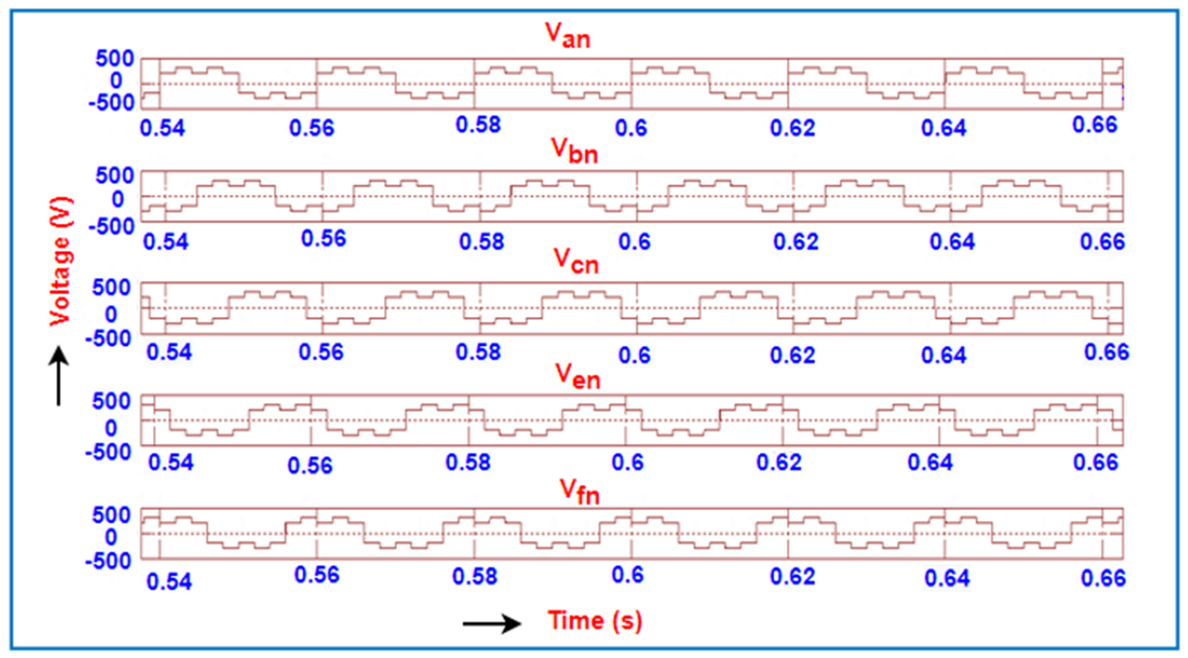
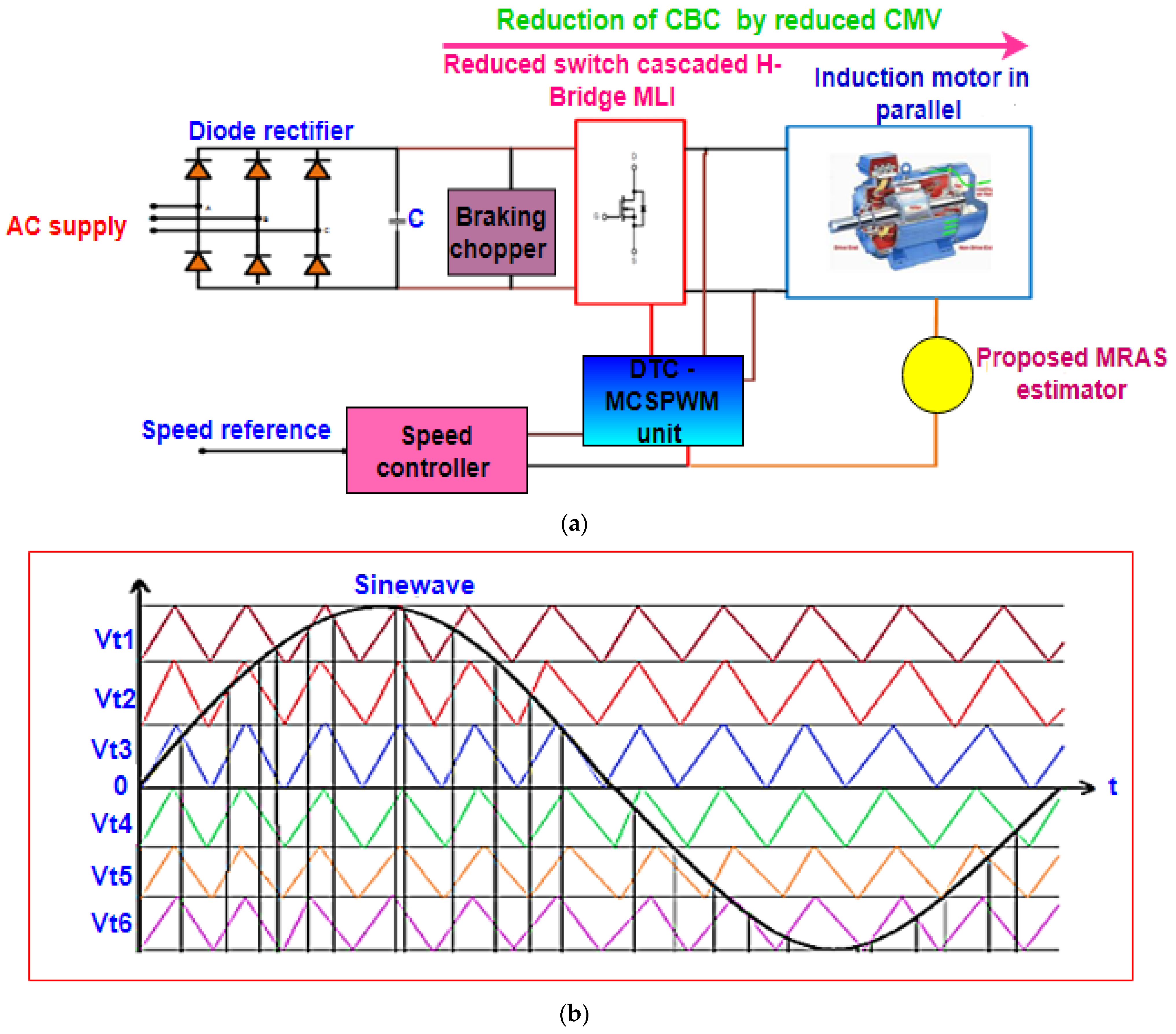
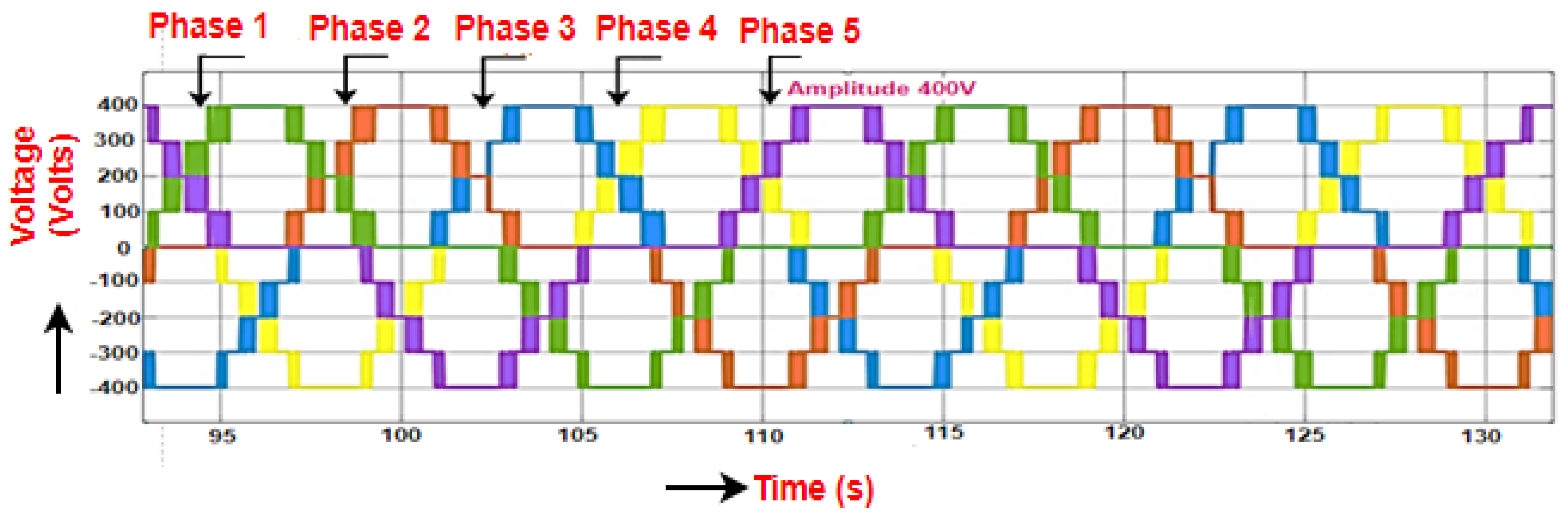
2. Modelling and Analysis of Five-Phase Inverter
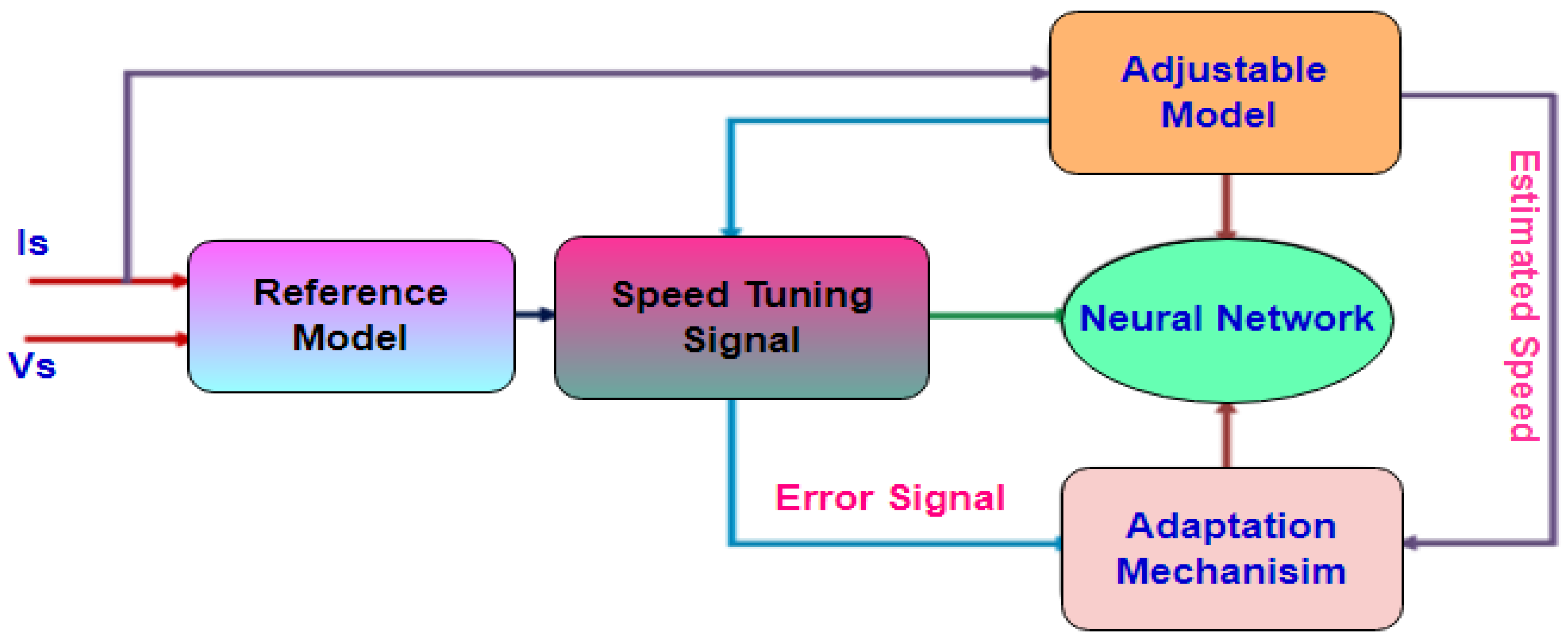
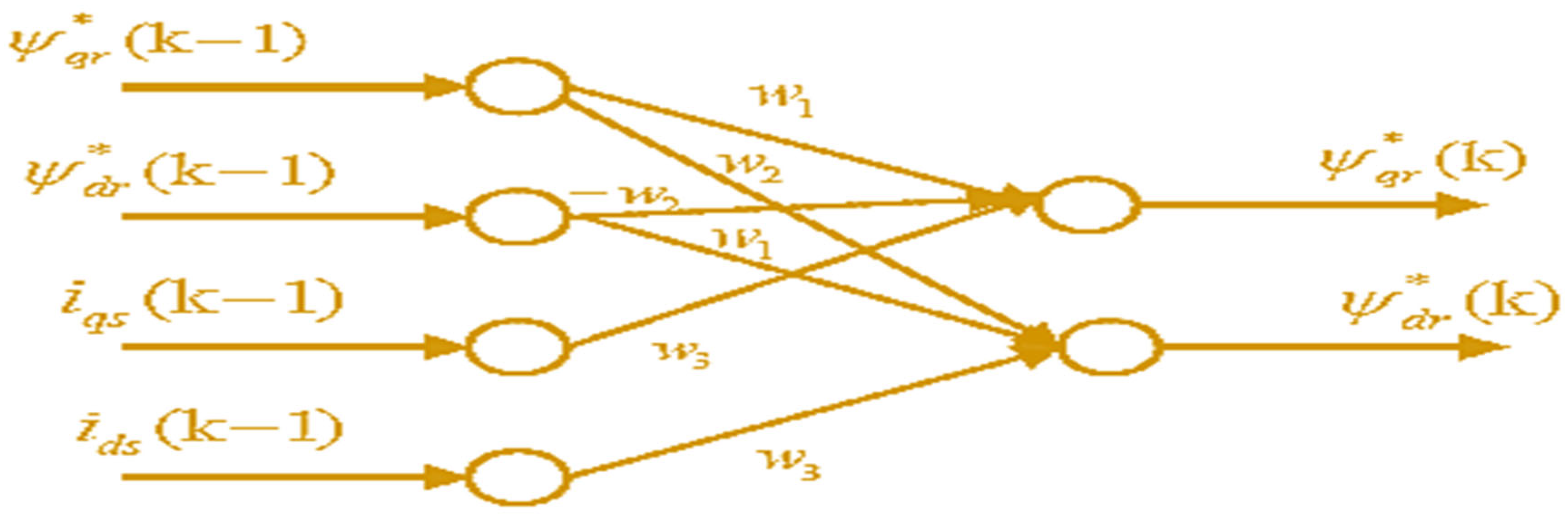
3. Artificial Neural Network Controlled Proposed Model Reference Adaptive System Technique
4. Modelling and Its Analysis of Multilevel Inverter Topologies for Induction Motor Traction Drive
4.1. T-Type Multilevel Inverter
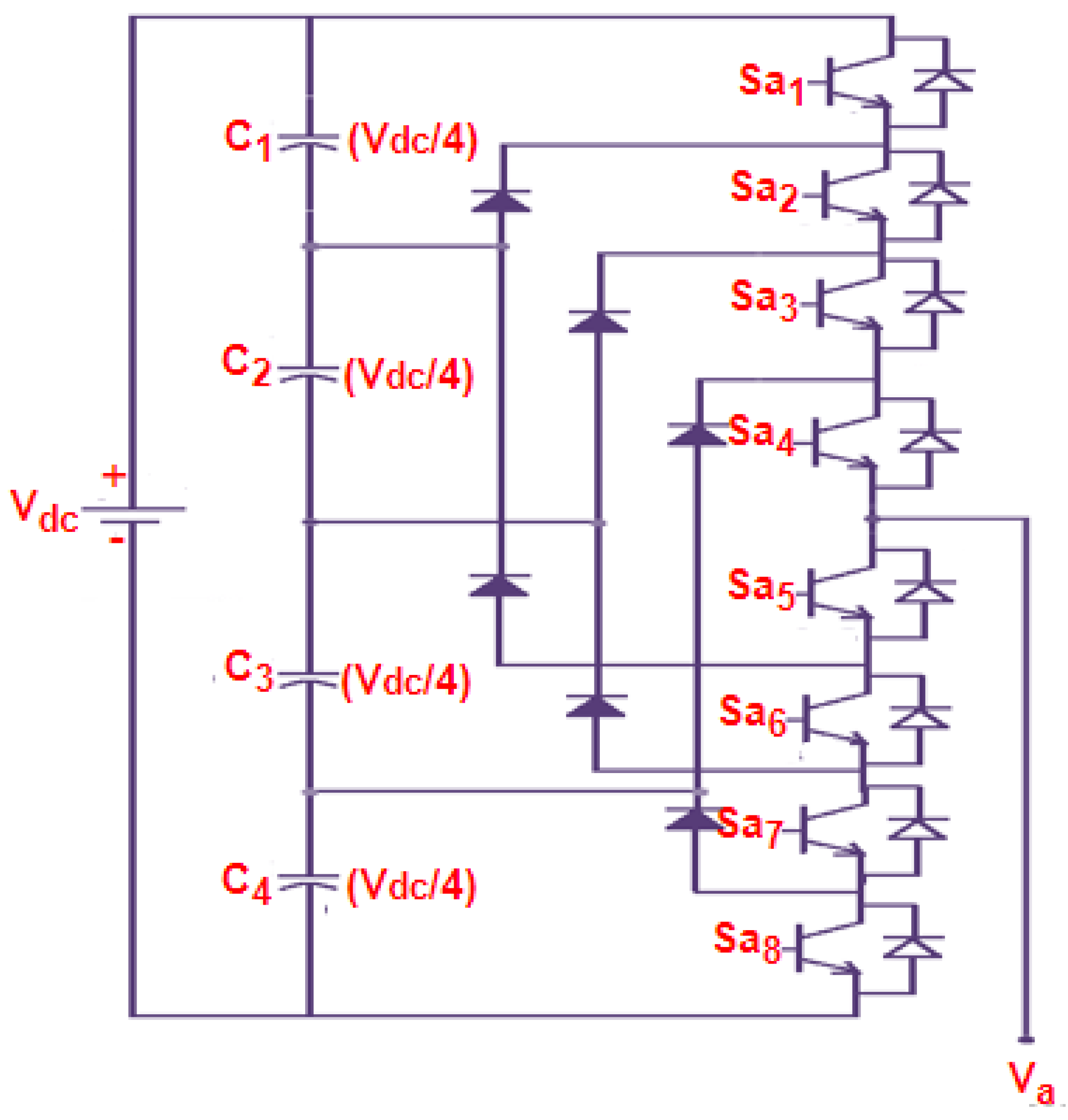
4.2. Neutral Point Clamped (NPC) Multilevel Inverter
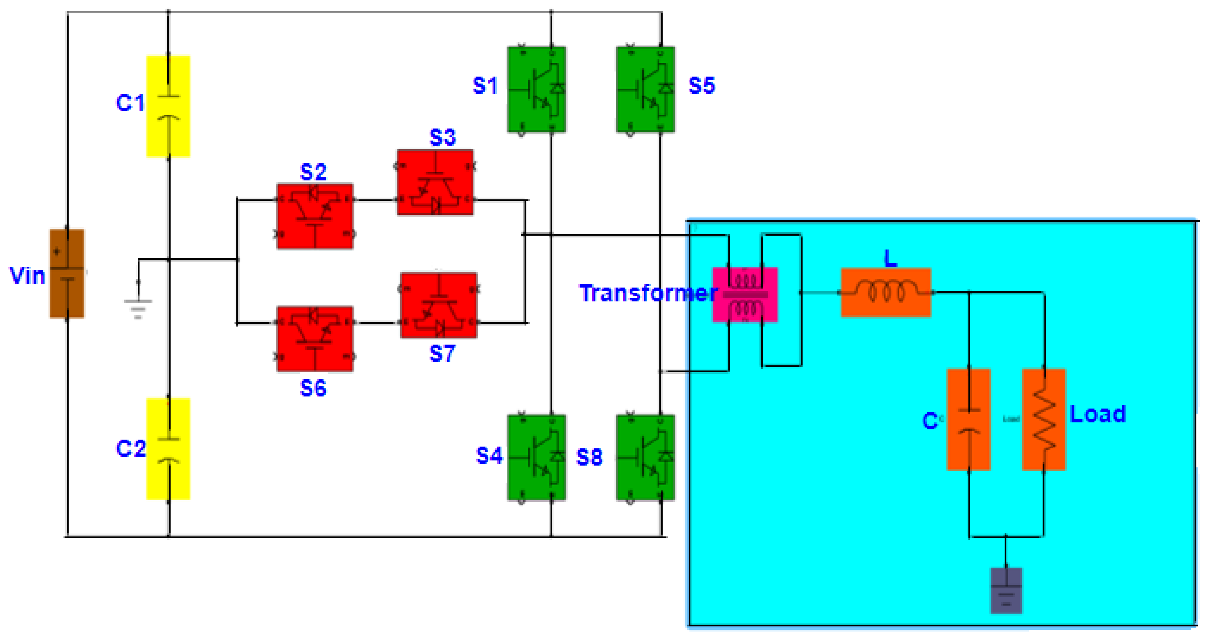
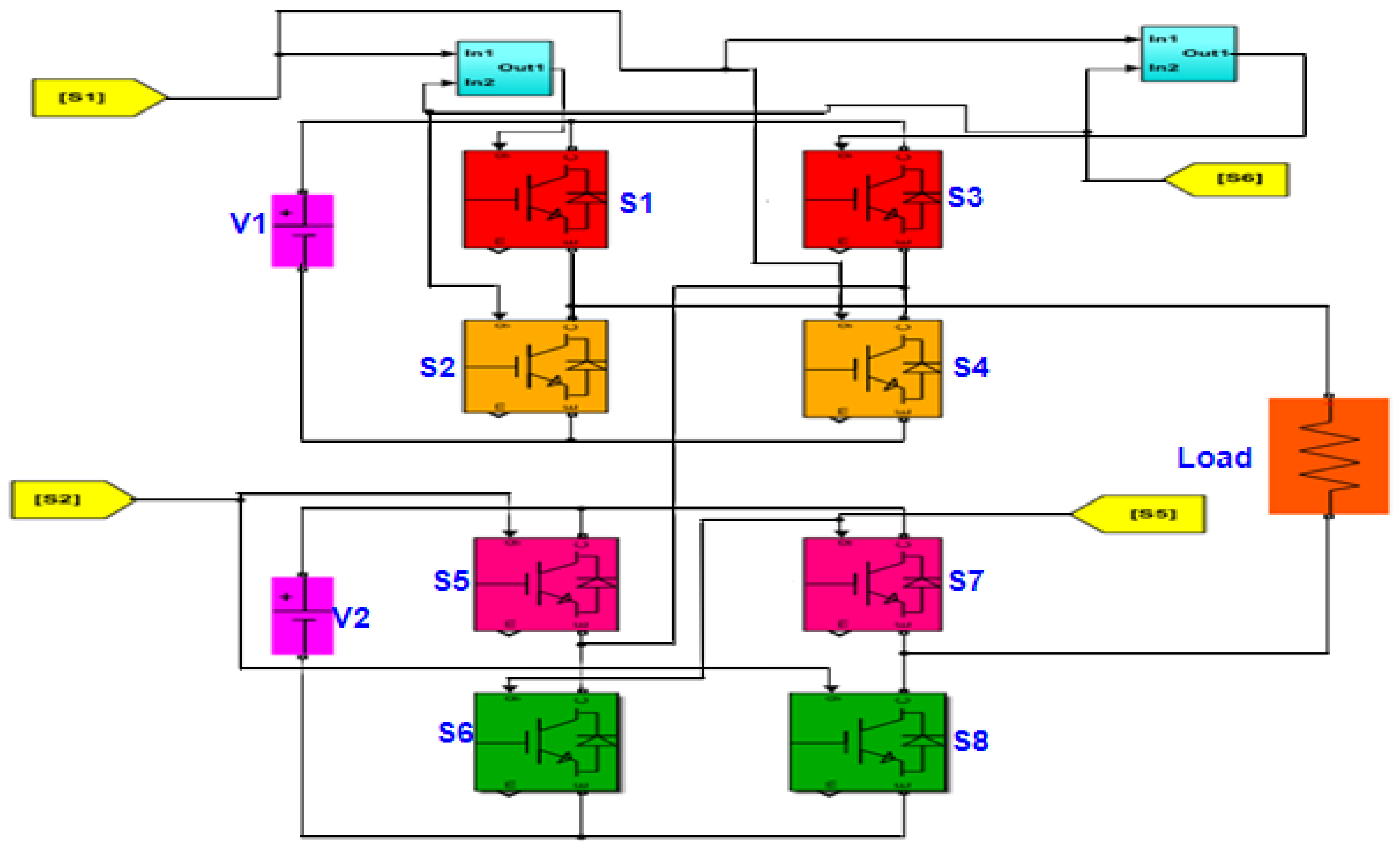
4.3. Cascaded H-Bridge Topology Inverter
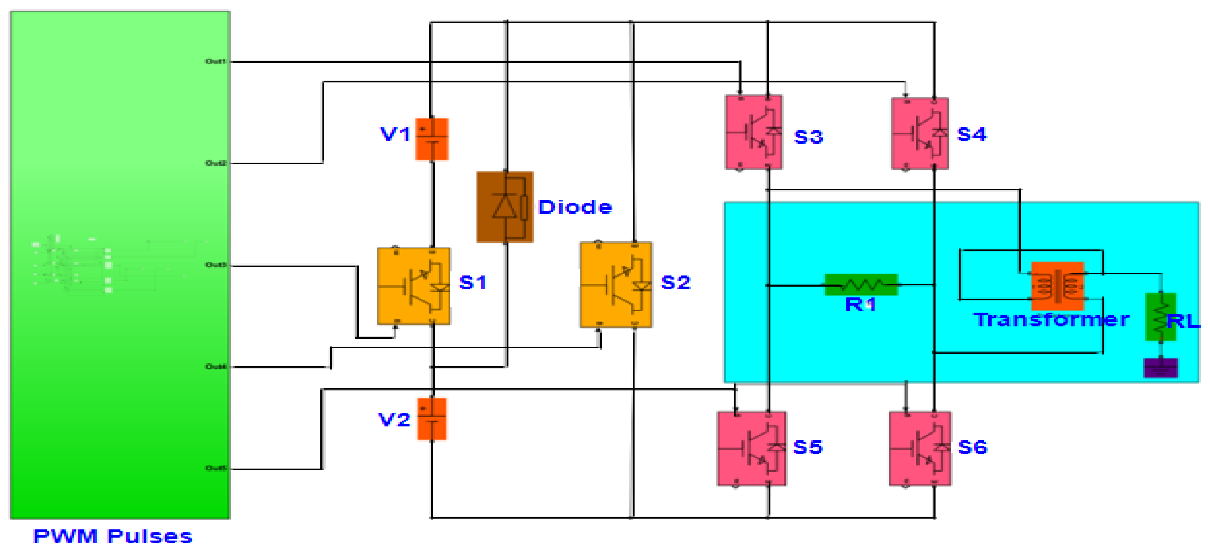
4.4. Proposed Reduced Switch Topology
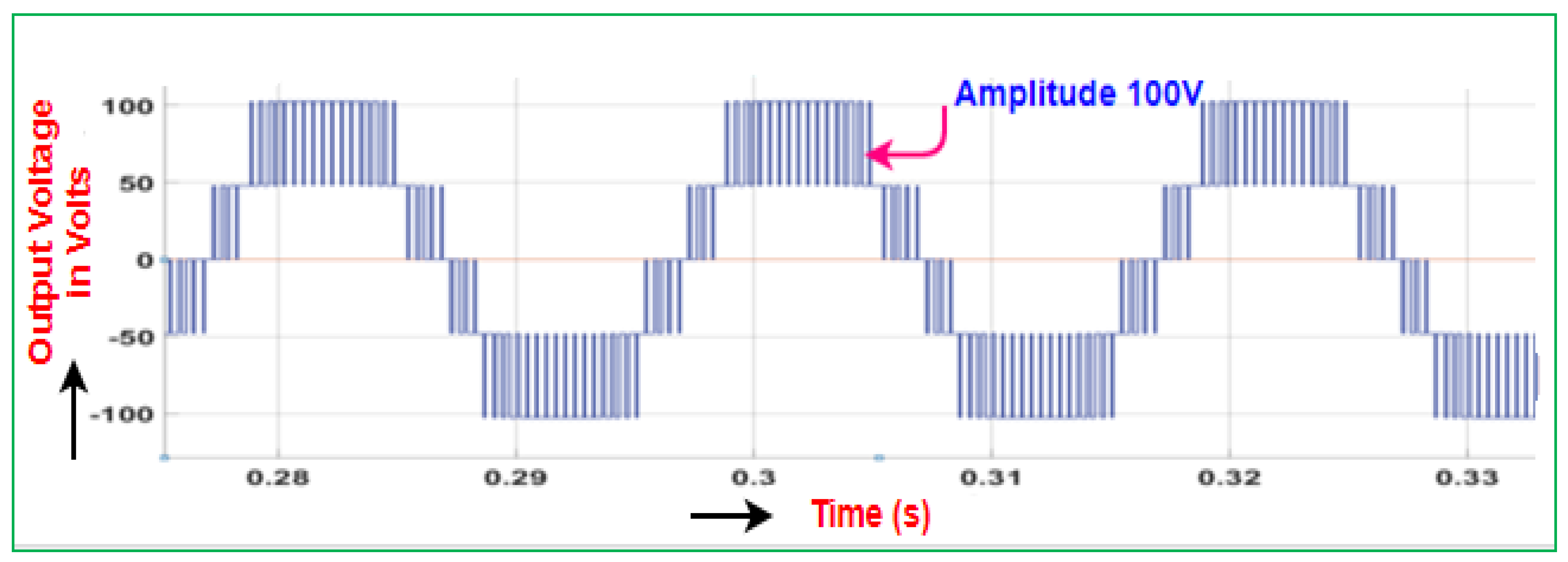
5. Simulation Results and Discussion
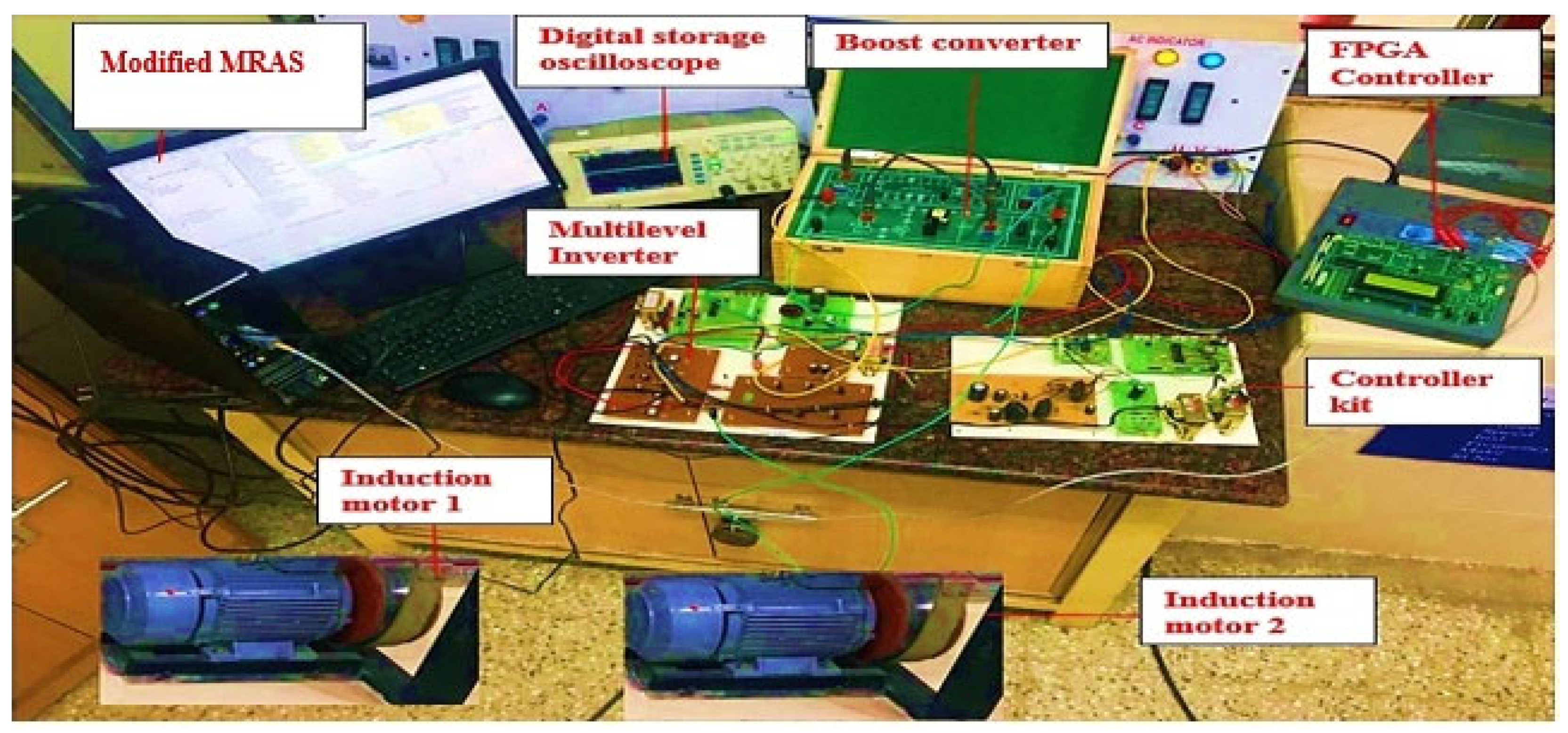
6. Hardware Results and Discussion
7. Conclusions
Author Contributions
Funding
Institutional Review Board Statement
Informed Consent Statement
Data Availability Statement
Conflicts of Interest
References
- Matsuse, K.; Kawai, H.; Kouno, Y.; Oikawa, J. Characteristics of speed sensorless vector controlled dual induction motor drive connected in parallel fed by a single Inverter. IEEE Trans. Ind. Appl. 2004, 40, 153–161. [Google Scholar] [CrossRef]
- Yazid, K.; Ibtiouen, R.; Touhami, O.; Fadel, M. Application of EKF to Parameters Estimation for Speed Sensorless and Neural Network Control of an Induction Motor. In Proceedings of the 6th WSEAS International Conference on Power Systems, Cambridge, UK, 23–25 February 2006; pp. 279–283. [Google Scholar]
- Abraham, L.A.; Arunchand, K.; Sudharshan, R. An Artificial-Intelligence Based Induction Motor Speed control and Estimation using conventional MRAS with dynamic reference modal. Int. J. Eng. Res. Appl. 2012, 2, 87–92. [Google Scholar]
- Zhen, L.; Xu, L. Sensorless field orientation control of induction machines based on a mutual MRAS scheme. IEEE Trans. Ind. Electron. 1998, 45, 824–831. [Google Scholar] [CrossRef]
- Gazafroodi, S.M.M.; Dashti, A. A Novel MRAS Based Estimator for Speed-Sensorless Induction Motor Drive. Iran. J. Electr. Electron. Eng. 2014, 10, 304–313. [Google Scholar]
- Julian, A.L.; Oriti, G.; Lipo, T.A. Elimination of common-mode voltage in three-phase sinusoidal power converters. IEEE Trans. Power Electron. 1999, 14, 982–989. [Google Scholar] [CrossRef]
- Dhatrak, R.K.; Nema, R.K.; Deshpande, D.M. Comparative Analysis of Common-Mode Voltage, Bearing Current and Shaft Voltage of Diode Clamped SPWM Multilevel Inverter Fed Induction Motor. Int. J. Electr. Electron. Eng. 2015, 4, 115–129. [Google Scholar] [CrossRef]
- Zou, B.; Guo, Y.; Xiao, X.; Yang, B.; Wang, X.; Shi, M.; Tu, Y. Performance Improvement of Matrix Converter Direct Torque Control System. Energies 2020, 13, 3247. [Google Scholar] [CrossRef]
- Muetze, A.; Binder, A. Calculation of Circulating Bearing Currents in Machines of Inverter-Based Drive Systems. IEEE Trans. Ind. Electron. 2007, 54, 932–938. [Google Scholar] [CrossRef]
- Cuzner, R.M.; Nowak, D.J.; Bendre, A.; Oriti, G.; Julian, A.L. Mitigating Circulating Common-Mode Currents between Parallel Soft-Switched Drive Systems. IEEE Trans. Ind. Appl. 2007, 43, 1284–1294. [Google Scholar] [CrossRef]
- Metz, A.; Binder, A. Don’t lose your bearings—Mitigation techniques for bearing currents in inverter-supplied drive systems. IEEE Ind. Appl. Mag. 2006, 12, 22–31. [Google Scholar]
- Firouzkouhi, H. Control of cascaded H-bridge multilevel inverter based on optimum regulation of switching angles, with FPGA implementations. Eur. J. Electr. Comput. Eng. 2019, 3, 1–5. [Google Scholar] [CrossRef][Green Version]
- Van Der Broeck, H.W.; Skudelny, H.C.; Stanke, G.V. Analysis and Realization of a Pulse width Modulator Based on Voltage Space Vectors. IEEE Trans. Ind. Appl. 1998, 24, 142–150. [Google Scholar] [CrossRef]
- Liu, R.; Ma, X.; Ren, X.; Cao, J.; Niu, S. Comparative Analysis of Bearing Current in Wind Turbine Generators. Energies 2018, 11, 1305. [Google Scholar] [CrossRef]
- Zalhaf, A.; Abdel-Salam, M.; Ahmed, M. An Active Common-Mode Voltage Canceler for PWM Converters in Wind-Turbine Doubly-Fed Induction Generators. Energies 2019, 12, 691. [Google Scholar] [CrossRef]
- Bharatiraja, C.; Selvaraj, R.; Chelliah, T.R.; Munda, J.L.; Tariq, M.; Maswood, A.I. Design and Implementation of Fourth Arm for Elimination of Bearing Current in NPC-MLI-Fed Induction Motor Drive. IEEE Trans. Ind. Appl. 2018, 54, 745–754. [Google Scholar] [CrossRef]
- Severson, E.; Gandikota, S.; Mohan, N. Practical Implementation of dual-purpose no-voltage drives for bearingless motors. IEEE Trans. Ind. Appl. 2016, 52, 1509–1518. [Google Scholar]
- Akagi, H.; Tamura, S. A passive EMI filter for elimination both bearing current and ground leakage current from an inverter-driven motor. IEEE Trans. Power Electron. 2006, 21, 1459–1469. [Google Scholar] [CrossRef]
- Nguyen, T.D.; Lee, H.H. Modulation strategies to reduce common-mode voltage for indirect matrix converters. IEEE Trans. Ind. Electron. 2012, 59, 129–140. [Google Scholar] [CrossRef]
- Sengamalai, U.; Chinnamuthu, S. Experimental fault analysis and speed control of an induction motor using a motor solver. J. Electron. Eng. Technol. 2017, 12, 761–768. [Google Scholar] [CrossRef]
- Usha, S.; Subramani, C.; Padmanaban, S. Neural Network-Based Model Reference Adaptive System for Torque Ripple Reduction in Sensorless Poly Phase Induction Motor Drive. Energies 2019, 12, 920. [Google Scholar] [CrossRef]
- Białoń, T.; Pasko, M.; Niestrój, R. Developing Induction Motor State Observers with Increased Robustness. Energies 2020, 13, 5487. [Google Scholar] [CrossRef]
- Adamczyk, M.; Orlowska-Kowalska, T. Self-Correcting Virtual Current Sensor Based on the Modified Luenberger Observer for Fault-Tolerant Induction Motor Drive. Energies 2021, 14, 6767. [Google Scholar] [CrossRef]


| States | On State Switches | Sa | Sb | Sc | Se | Sf | Van | Vbn | Vcn | Ven | Vfn |
|---|---|---|---|---|---|---|---|---|---|---|---|
| 1 | S4 S6 S8 S10 S2 | 0 | 0 | 0 | 0 | 0 | 0 | 0 | 0 | 0 | 0 |
| 2 | S1 S6 S8 S10 S2 | 1 | 0 | 0 | 0 | 0 | 4/5 Vd | −1/5 Vd | −1/5 Vd | −1/5 Vd | −1/5 Vd |
| 3 | S1 S3 S8 S10 S2 | 1 | 1 | 0 | 0 | 0 | 3/5 Vd | 3/5 Vd | −2/5 Vd | −2/5 Vd | −2/5 Vd |
| 4 | S1 S3 S5 S10 S2 | 1 | 1 | 1 | 0 | 0 | 2/5 Vd | 2/5 Vd | 2/5 Vd | −3/5 Vd | −3/5 Vd |
| 5 | S1 S6 S5 S10 S2 | 1 | 0 | 1 | 0 | 0 | 3/5 Vd | −2/5 Vd | 3/5 Vd | −2/5 Vd | −2/5 Vd |
| 6 | S4 S6 S5 S10 S2 | 0 | 0 | 1 | 0 | 0 | −1/5 Vd | −1/5 Vd | 4/5 Vd | −1/5 Vd | −1/5 Vd |
| 7 | S4 S3 S5 S10 S2 | 0 | 1 | 1 | 0 | 0 | −2/5 Vd | 3/5 Vd | 3/5 Vd | −2/5 Vd | −2/5 Vd |
| 8 | S4 S3 S8 S10 S2 | 0 | 1 | 0 | 0 | 0 | −1/5 Vd | 4/5 Vd | −1/5 Vd | −1/5 Vd | −1/5 Vd |
| 9 | S4 S3 S8 S7 S2 | 0 | 1 | 0 | 1 | 0 | −2/5 Vd | 3/5 Vd | −2/5 Vd | 3/5 Vd | −2/5 Vd |
| 10 | S1 S3 S8 S7 S2 | 1 | 1 | 0 | 1 | 0 | 2/5 Vd | 2/5 Vd | −3/5 Vd | 2/5 Vd | −3/5 Vd |
| 11 | S1 S6 S8 S7 S2 | 1 | 0 | 0 | 1 | 0 | 3/5 Vd | −2/5 Vd | −2/5 Vd | 3/5 Vd | −2/5 Vd |
| 12 | S4 S6 S8 S7 S2 | 0 | 0 | 0 | 1 | 0 | −1/5 Vd | −1/5 Vd | −1/5 Vd | 4/5 Vd | −1/5 Vd |
| 13 | S4 S6 S5 S7 S2 | 0 | 0 | 1 | 1 | 0 | −2/5 Vd | −2/5 Vd | 3/5 Vd | 3/5 Vd | −2/5 Vd |
| 14 | S1 S6 S5 S7 S2 | 1 | 0 | 1 | 1 | 0 | 2/5 Vd | −3/5 Vd | 2/5 Vd | 2/5 Vd | −3/5 Vd |
| 15 | S1 S3 S5 S7 S2 | 1 | 1 | 1 | 1 | 0 | 1/5 Vd | 1/5 Vd | 1/5 Vd | 1/5 Vd | −4/5 Vd |
| 16 | S4 S3 S5 S7 S2 | 0 | 1 | 1 | 1 | 0 | −3/5 Vd | 2/5 Vd | 2/5 Vd | 2/5 Vd | −3/5 Vd |
| 17 | S4 S3 S5 S7 S9 | 0 | 1 | 1 | 1 | 1 | −4/5 Vd | 1/5 Vd | 1/5 Vd | 1/5 Vd | 1/5 Vd |
| 18 | S1 S3 S5 S7 S9 | 1 | 1 | 1 | 1 | 1 | 0 | 0 | 0 | 0 | 0 |
| 19 | S1 S6 S5 S7 S9 | 1 | 0 | 1 | 1 | 1 | 1/5 Vd | −4/5 Vd | 1/5 Vd | 1/5 Vd | 1/5 Vd |
| 20 | S4 S6 S5 S7 S9 | 0 | 0 | 1 | 1 | 1 | −3/5 Vd | −3/5 Vd | 2/5 Vd | 2/5 Vd | 2/5 Vd |
| 21 | S4 S6 S8 S7 S9 | 0 | 0 | 0 | 1 | 1 | −2/5 Vd | −2/5 Vd | −2/5 Vd | 3/5 Vd | 3/5 Vd |
| 22 | S1S6S8 S7 S9 | 1 | 0 | 0 | 1 | 1 | 2/5 Vd | −3/5 Vd | −3/5 Vd | 2/5 Vd | 2/5 Vd |
| 23 | S1 S3 S8 S7 S9 | 1 | 1 | 0 | 1 | 1 | 1/5 Vd | 1/5 Vd | −4/5 Vd | 1/5 Vd | 1/5 Vd |
| 24 | S4 S3 S8 S7 S9 | 0 | 1 | 0 | 1 | 1 | −3/5 Vd | 2/5 Vd | −3/5 Vd | 2/5 Vd | 2/5 Vd |
| 25 | S4S3 S8 S10 S9 | 0 | 1 | 0 | 0 | 1 | −2/5 Vd | 3/5 Vd | −2/5 Vd | −2/5 Vd | 3/5 Vd |
| 26 | S1 S3 S8 S10 S9 | 1 | 1 | 0 | 0 | 1 | 2/5 Vd | 2/5 Vd | −3/5 Vd | −3/5 Vd | 2/5 Vd |
| 27 | S1 S3 S5 S10 S9 | 1 | 1 | 1 | 0 | 1 | 1/5 Vd | 1/5 Vd | 1/5 Vd | −4/5 Vd | 1/5 Vd |
| 28 | S4 S3 S5 S10 S9 | 0 | 1 | 1 | 0 | 1 | −3/5 Vd | 2/5 Vd | 2/5 Vd | −3/5 Vd | 2/5 Vd |
| 29 | S4 S6 S5 S10 S9 | 0 | 0 | 1 | 0 | 1 | −2/5 Vd | −2/5 Vd | 3/5 Vd | −2/5 Vd | 3/5 Vd |
| 30 | S1 S6 S5 S10 S9 | 1 | 0 | 1 | 0 | 1 | 2/5 Vd | −3/5 Vd | 2/5 Vd | −3/5 Vd | 2/5 Vd |
| 31 | S1 S6 S8 S10 S9 | 1 | 0 | 0 | 1 | 0 | 3/5 Vd | −2/5 Vd | −2/5 Vd | 3/5 Vd | −2/5 Vd |
| 32 | S4 S6 S8 S10 S9 | 0 | 0 | 0 | 0 | 1 | −1/5 Vd | −1/5 Vd | −1/5 Vd | −1/5 Vd | 4/5 Vd |
| States | On State Switches | Sa | Sb | Sc | Se | Sf | Vab | Vbc | Vce | Vef | Vfa |
|---|---|---|---|---|---|---|---|---|---|---|---|
| 1 | S4 S6 S8 S10 S2 | 0 | 0 | 0 | 0 | 0 | 0 | 0 | 0 | 0 | 0 |
| 2 | S1 S6 S8 S10 S2 | 1 | 0 | 0 | 0 | 0 | Vd | 0 | 0 | 0 | 0 |
| 3 | S1 S3 S8 S10 S2 | 1 | 1 | 0 | 0 | 0 | 0 | Vd | 0 | 0 | −Vd |
| 4 | S1 S3 S5 S10 S2 | 1 | 1 | 1 | 0 | 0 | 0 | 0 | Vd | 0 | −Vd |
| 5 | S1 S6 S5 S10 S2 | 1 | 0 | 1 | 0 | 0 | Vd | −Vd | Vd | 0 | −Vd |
| 6 | S4 S6 S5 S10 S2 | 0 | 0 | 1 | 0 | 0 | 0 | 0 | −Vd | Vd | 0 |
| 7 | S4 S3 S5 S10 S2 | 0 | 1 | 1 | 0 | 0 | −Vd | 0 | Vd | 0 | 0 |
| 8 | S4 S3 S8 S10 S2 | 0 | 1 | 0 | 0 | 0 | −Vd | Vd | 0 | 0 | 0 |
| 9 | S4 S3 S8 S7 S2 | 0 | 1 | 0 | 1 | 0 | −Vd | Vd | Vd | Vd | 0 |
| 10 | S1 S3 S8 S7 S2 | 1 | 1 | 0 | 1 | 0 | 0 | Vd | Vd | Vd | Vd |
| 11 | S1 S6 S8 S7 S2 | 1 | 0 | 0 | 1 | 0 | Vd | 0 | Vd | Vd | Vd |
| 12 | S4 S6 S8 S7 S2 | 0 | 0 | 0 | 1 | 0 | 0 | 0 | −Vd | Vd | 0 |
| 13 | S4 S6 S5 S7 S2 | 0 | 0 | 1 | 1 | 0 | −Vd | Vd | 0 | Vd | 0 |
| 14 | S1 S6 S5 S7 S2 | 1 | 0 | 1 | 1 | 0 | Vd | −Vd | 0 | Vd | −Vd |
| 15 | S1 S3 S5 S7 S2 | 1 | 1 | 1 | 1 | 0 | 0 | 0 | 0 | Vd | −Vd |
| 16 | S4 S3 S5 S7 S2 | 0 | 1 | 1 | 1 | 0 | −Vd | 0 | 0 | Vd | 0 |
| 17 | S4 S3 S5 S7 S9 | 0 | 1 | 1 | 1 | 1 | −Vd | 0 | 0 | 0 | Vd |
| 18 | S1 S3 S5 S7 S9 | 1 | 1 | 1 | 1 | 1 | 0 | 0 | 0 | 0 | 0 |
| 19 | S1 S6 S5 S7 S9 | 1 | 0 | 1 | 1 | 1 | Vd | −Vd | 0 | 0 | 0 |
| 20 | S4 S6 S5 S7 S9 | 0 | 0 | 1 | 1 | 1 | 0 | −Vd | 0 | 0 | Vd |
| 21 | S4 S6 S8 S7 S9 | 0 | 0 | 0 | 1 | 1 | 0 | 0 | −Vd | 0 | Vd |
| 22 | S1 S6 S8 S7 S9 | 1 | 0 | 0 | 1 | 1 | Vd | 0 | −Vd | 0 | 0 |
| 23 | S1 S3 S8 S7 S9 | 1 | 1 | 0 | 1 | 1 | 0 | Vd | −Vd | 0 | 0 |
| 24 | S4 S3 S8 S7 S9 | 0 | 1 | 0 | 1 | 1 | −Vd | Vd | −Vd | 0 | Vd |
| 25 | S4S3 S8 S10 S9 | 0 | 1 | 0 | 0 | 1 | −Vd | Vd | 0 | −Vd | Vd |
| 26 | S1 S3 S8 S10 S9 | 1 | 1 | 0 | 0 | 1 | 0 | Vd | 0 | −Vd | 0 |
| 27 | S1 S3 S5 S10 S9 | 1 | 1 | 1 | 0 | 1 | 0 | 0 | Vd | −Vd | 0 |
| 28 | S4 S3 S5 S10 S9 | 0 | 1 | 1 | 0 | 1 | −Vd | 0 | Vd | −Vd | Vd |
| 29 | S4 S6 S5 S10 S9 | 0 | 0 | 1 | 0 | 1 | 0 | −Vd | Vd | −Vd | Vd |
| 30 | S1 S6 S5 S10 S9 | 1 | 0 | 1 | 0 | 1 | Vd | −Vd | Vd | Vd | 0 |
| 31 | S1 S6 S8 S10 S9 | 1 | 0 | 0 | 1 | 0 | Vd | 0 | −Vd | Vd | −Vd |
| 32 | S4 S6 S8 S10 S9 | 0 | 0 | 0 | 0 | 1 | 0 | 0 | 0 | −Vd | Vd |
| Output Voltage(Vo) | Sa1 | Sa2 | Sa3 | Sa4 | Sa5 | Sa6 | Sa7 | Sa8 |
|---|---|---|---|---|---|---|---|---|
| +Vdc/2 V | On | On | On | On | Off | Off | Off | Off |
| +Vdc/4 V | Off | On | On | On | On | Off | Off | Off |
| 0 V | Off | Off | On | On | On | On | Off | Off |
| −Vdc/4 V | Off | Off | Off | On | On | On | On | Off |
| −Vdc/2 V | Off | Off | Off | Off | On | On | On | On |
| V0 | S1 | S2 | S3 | S4 | S5 | S6 | S7 | S8 |
|---|---|---|---|---|---|---|---|---|
| Vd/2 | On | On | On | On | Off | Off | Off | Off |
| Vd/4 | Off | On | On | On | On | Off | Off | Off |
| 0 | Off | Off | On | On | On | On | Off | Off |
| −Vd/4 | Off | Off | Off | On | On | On | On | Off |
| −Vd/2 | Off | Off | Off | Off | On | On | On | On |
| S. No. | S1 | S2 | S3 | S4 | S5 | S6 | Voltage at Load |
|---|---|---|---|---|---|---|---|
| 1 | On | Off | On | Off | Off | On | V1 |
| 2 | On | Off | On | Off | On | Off | V1 + V2 |
| 3 | On | Off | On | Off | Off | On | V1 |
| 4 | Off | On | On | Off | Off | On | −V1 |
| 5 | Off | On | On | Off | On | Off | −V1 − V2 |
| 6 | Off | On | On | Off | Off | On | −V1 |
| Parameters | Two Level VSI | T-Bridge MLI | NPC-MLI | H-Bridge MLI | Modified H-Bridge MLI | |
|---|---|---|---|---|---|---|
| CMC-SPWM (V) | Hardware | 390 | 100 | 40 | 36 | 25 |
| Theoretical | 389.5 | 99.03 | 40.048 | 36.88 | 25.43 | |
| CMC-MCPWM (V) | Hardware | 200 | 42 | 20 | 10 | 6 |
| Theoretical | 200.02 | 42.5 | 19.9 | 9.98 | 5.8 | |
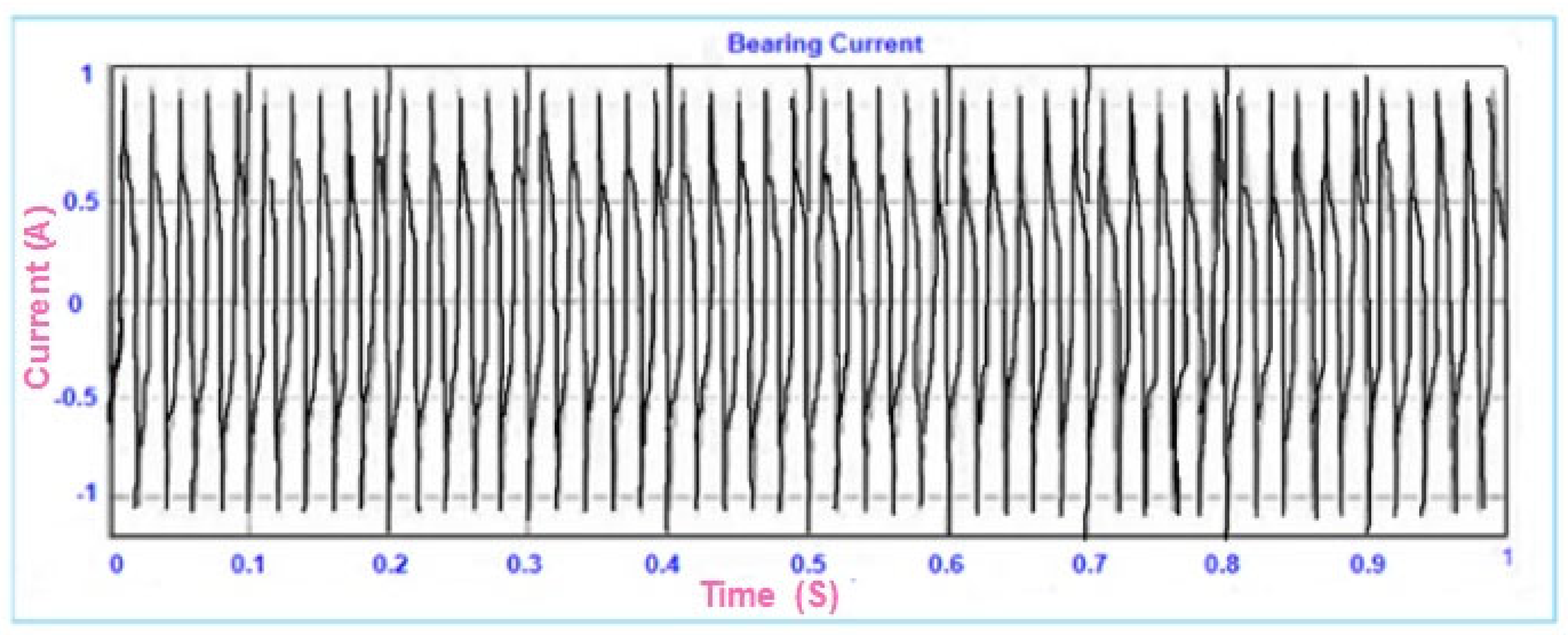
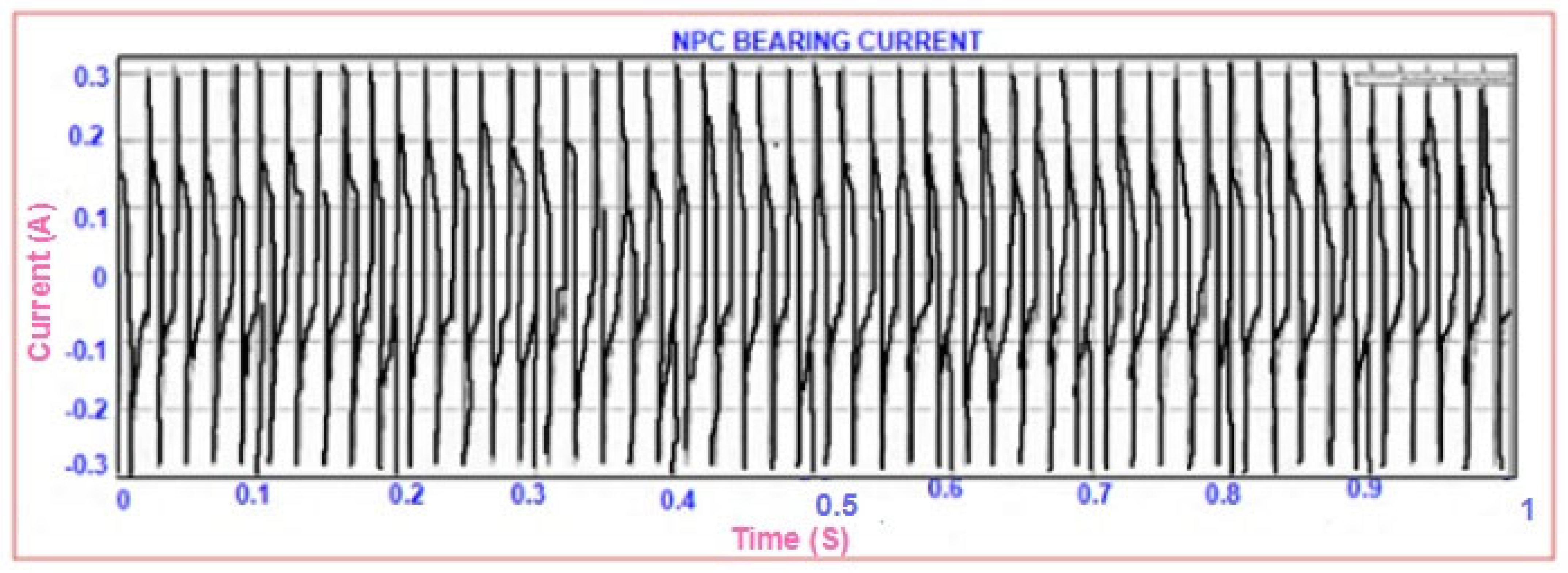
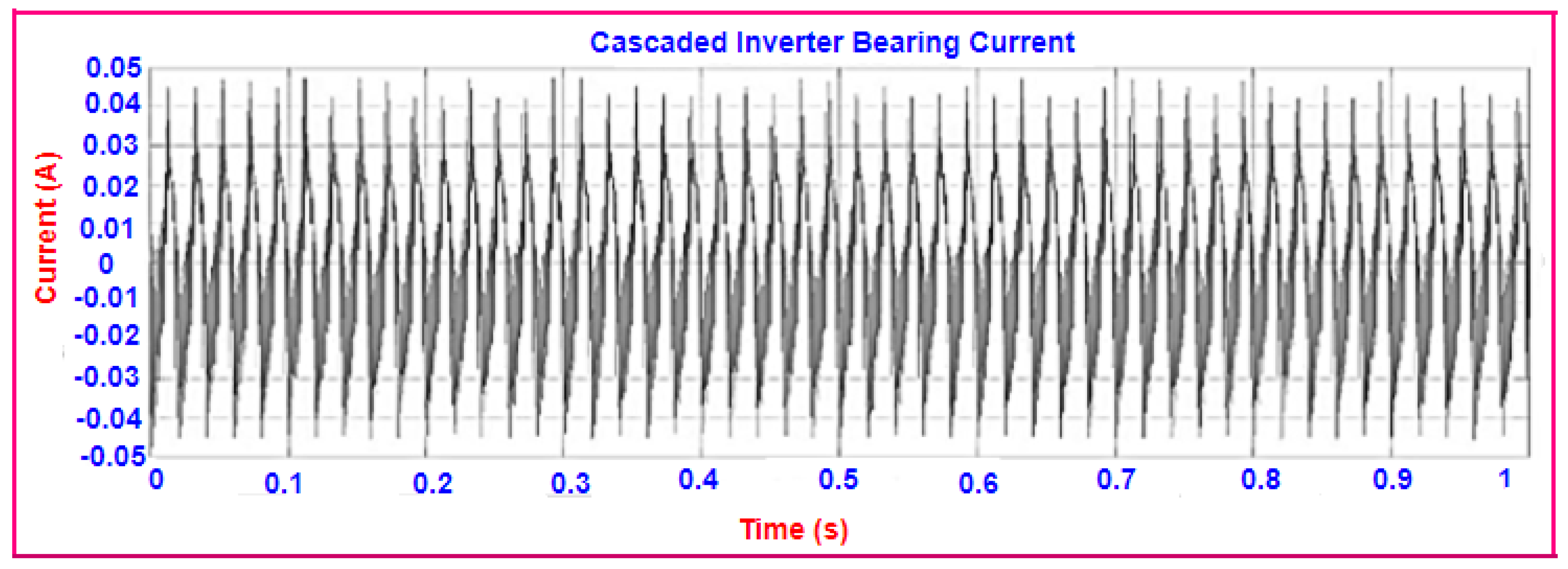
| CBC (A) | Hardware | 10 | 0.9 | 0.3 | 0.045 | 0.025 |
| Theoretical | 9.8 | 0.986 | 0.17 | 0.06 | 0.036 | |
Publisher’s Note: MDPI stays neutral with regard to jurisdictional claims in published maps and institutional affiliations. |
© 2022 by the authors. Licensee MDPI, Basel, Switzerland. This article is an open access article distributed under the terms and conditions of the Creative Commons Attribution (CC BY) license (https://creativecommons.org/licenses/by/4.0/).
Share and Cite
Sengamalai, U.; Thamizh Thentral, T.M.; Ramasamy, P.; Bajaj, M.; Hussain Bukhari, S.S.; Elattar, E.E.; Althobaiti, A.; Kamel, S. Mitigation of Circulating Bearing Current in Induction Motor Drive Using Modified ANN Based MRAS for Traction Application. Mathematics 2022, 10, 1220. https://doi.org/10.3390/math10081220
Sengamalai U, Thamizh Thentral TM, Ramasamy P, Bajaj M, Hussain Bukhari SS, Elattar EE, Althobaiti A, Kamel S. Mitigation of Circulating Bearing Current in Induction Motor Drive Using Modified ANN Based MRAS for Traction Application. Mathematics. 2022; 10(8):1220. https://doi.org/10.3390/math10081220
Chicago/Turabian StyleSengamalai, Usha, T. M. Thamizh Thentral, Palanisamy Ramasamy, Mohit Bajaj, Syed Sabir Hussain Bukhari, Ehab E. Elattar, Ahmed Althobaiti, and Salah Kamel. 2022. "Mitigation of Circulating Bearing Current in Induction Motor Drive Using Modified ANN Based MRAS for Traction Application" Mathematics 10, no. 8: 1220. https://doi.org/10.3390/math10081220
APA StyleSengamalai, U., Thamizh Thentral, T. M., Ramasamy, P., Bajaj, M., Hussain Bukhari, S. S., Elattar, E. E., Althobaiti, A., & Kamel, S. (2022). Mitigation of Circulating Bearing Current in Induction Motor Drive Using Modified ANN Based MRAS for Traction Application. Mathematics, 10(8), 1220. https://doi.org/10.3390/math10081220