Abstract
Multilevel converters have been broadly used in wind energy conversion systems (WECS) to set the generator angular speed to a certain value, which allows maximizing wind power extraction; nevertheless, power that is drawn out from WECS strongly depends on the power coefficient and the ability to operate at the optimal tip speed ratio that corresponds to the maximum power coefficient. This work presents a novel and formal steady-state analysis to demonstrate the reverse relationship between the duty cycle of a multilevel boost converter (MBC) and the angular speed of a permanent magnet synchronous generator (PMSG). The study was based on the d–q transformation using the rotor reference frame. It was carried out by employing a reduced order dynamic system that included an equivalent electrical load resistance as a representation for the subsystems that were cascade-connected at the terminals of the PMSG. The steady-state characteristic was obtained by using the definition of equilibrium point. The set of nonlinear equations that represents the steady state of this WECS was solved by using the Newton method; besides, an analysis that considers the equivalent load as a bifurcation parameter demonstrates that the number of equilibria never changes.
Keywords:
bifurcation analysis; d–q transform modeling; dynamic systems control; permanent magnet synchronous generator; multilevel boost converter MSC:
37N35; 37M99
1. Introduction
Wind energy conversion systems have multiplied considerably in recent decades. According to the latest GWEC report, their total installed power exceeds 650 GW [1]. Intelligent and innovative technologies based on various investigations related to the optimization of the extraction of wind power have been developed in recent years, such as optimization methodologies for avoiding low outputs, extreme-seeking control, yaw-based wake, angle control, and artificial neural networks [2,3,4,5,6,7,8]. Appropriately, there are several reviews on the state of the art of WECS regarding emerging technologies, innovative systems, trends, and challenges, demonstrating its importance [9,10,11,12,13].
In terms of wind energy extraction, the use of multilevel converters has been widely used [14,15,16,17]. In the more traditional models, a controller is in charge of sending a typically adjusted signal and then injecting it in the MBC’s duty cycle. Regardless of the elements used in the control law, it is essential to guarantee optimization in wind energy extraction.
In general, for a given wind speed, there is an angular speed of the rotor of the associated turbine that allows optimization of the wind power extraction. The function of the control system is to supply the MBC with the appropriate signal so that the amount of energy extracted from the WECS is such that the speed of the turbine rotor is optimal according to the wind speed at that time [18].
In this sense, it is essential to determine the relationship between the input and the system’s output, this is, between the MBC duty cycle and the angular velocity of the wind turbine rotor, to allow for establishing a more appropriate control action for energy efficiency.
Within the WECS, there are two variants of coupling between the turbine and the generator. One is through a gearbox that multiplies the speed of the turbine rotor towards the generator, and the other is the direct-drive connection, where the angular speeds of the turbine and the generator have the same value [9]. It is common to use a PMSG in this mode of operation [19,20,21,22,23]; in fact, that is the configuration used in the analysis performed in this work. PMS generators present several advantages and have been widely used in WECS. Some interesting studies have been developed regardless of sensorless adaptive output feedback control, as shown in [24,25].
There are works in which a representation of variable load resistance is used at the output of the PMSG to analyze the phenomena in PMSG-based WECS. This resistance replaces a higher-order model for the uncontrolled rectifier, the MBC, the three-phase inverter, and the three-phase load. For example, in [26], a comprehensive MPPT was developed and validated for the full range of operating wind speed. In contrast, a unified dynamic model of the wind turbine generator was built to simplify the analysis. On the other hand, in [27], a neuro-adaptive generalized global sliding mode controller was used for maximizing wind power extraction using an equivalent model for the WECS.
For the particular case in which a purely resistive three-phase load is connected, it seems natural that the relationship between the input and the output of the mentioned system is inverse. However, no formal study has demonstrated this relationship, nor is there a complementary one which has demonstrated that a stable equilibrium exists and that it is unique. Using open-loop steady-state analysis, we studied those issues in this work.
This paper mainly presents a formal and innovative analysis that demonstrates the inverse relationship between the duty cycle of an MBC converter and the angular speed of the rotor of a PMSG in a direct-drive WECS for a purely resistive three-phase load. It also demonstrates the absence of the nonlinear bifurcation phenomenon. It shows the existence of an equilibrium for each value of the duty cycle and that it is stable.
PMSG was modeled using the d–q transform. The system of the uncontrolled rectifier, the 2N-MBC, the three-phase inverter, and the three-phase load were taken as variable equivalent electrical load resistances dependent on the duty cycle.
The paper is organized as follows: Section 2 provides a general overview of features of the WECS this analysis is based on. In Section 3, the mathematical model we solve is presented. Section 4 details the procedure for solving the mathematical model. Section 5 shows the results obtained, and finally, Section 6 summarizes the conclusions and future works.
2. General Features of the Wind Energy Conversion System
The WECS this study is based on is represented in Figure 1.
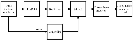
Figure 1.
General overview of the WECS used in this research.
The block associated with the wind turbine emulator in Figure 1 was experimentally implemented by utilizing a Linux-based real-time platform, a variable speed drive, and an induction motor; see Figure 2. Once wind speed was specified as an input for this wind turbine emulator, the value for the mechanical torque was computed, and its corresponding signal was connected to the variable speed drive. This device was responsible for applying adequate voltages to the induction motor such that experimental mechanical torque at the motor shaft reached its desired value. Additionally, the value of rotor speed that maximizes wind power extraction () was computed as required for the closed-loop implementation.
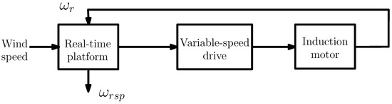
Figure 2.
Wind turbine emulator.
The experimental wind turbine emulator that included the induction motor, was directly connected to the PMSG (gearless configuration). One of the advantages of this type of WECS is that installation of a gearbox is avoided, along with the problems related to its use [28,29,30], making it a less expensive configuration. Furthermore, since its operating speeds in the asynchronous mode are extensive, the PMSG is preferred over other electrical generators [26]. Table 1 shows the parameters associated with the experimental four-pole three-phase PMSG.

Table 1.
Parameters associated with the PMSG.
This WECS contained a three-phase full-rated full-wave diode rectifier for transforming the variable frequency voltage at the terminals of the generator into a varying magnitude DC voltage. Power was then transferred from the output of the diode rectifier to the custom-made full-rated 2N-MBC [31,32]. The experimental PWM frequency of the 2N-MBC was 50 kHz. The discrete-time controller in Figure 1 defined in real-time the duty cycle of the 2N-MBC. An IGBT-based full-rated voltage source inverter was utilized to transfer power from the output of the 2N-MBC to the wye-connected electrical load. The frequency at the output terminals of the source inverter was fixed at 60 Hz; in other words, the electric load was always fed by a set of 60 Hz three-phase voltages. The PMSG used in this work was manufactured by Wind-Blue Power. Its rated power and rated rotor speed are 300 W and 1800 RPM, respectively. Figure 3 shows the experimental emulator.
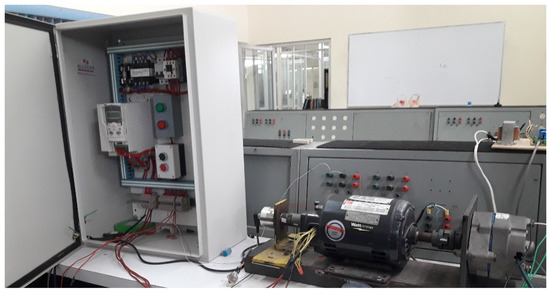
Figure 3.
Experimental emulator used in this research.
More details regarding to the methodology and instrumentation used in the experimental setup, along with the controller performance to maximize wind power extraction, can be found in [33].
3. Mathematical Model
A formal, open-loop, steady-state analysis is described in this section, which was used to investigate the inverse relationship between the input and the system’s output to be controlled and the occurrence of nonlinear bifurcation phenomena. The input was the duty cycle (D) applied to the 2N-MBC, and the output was the turbine-generator speed (). This study is significant, as the WECS extracted power is noticeably affected by the power coefficient (), a function whose monotonicity may grow or diminish along the tip speed ratio axis ().
To simplify the high-order model representative of the uncontrolled rectifier, the 2N-MBC, and the three-phase inverter and load, as shown in Figure 1, a mathematical expression to calculate a variable equivalent electrical load resistance is proposed, as shown in Equation (1). It is worth mentioning that some works where similar topology employs a variant resistor to analyze phenomena in PMSG-based WECS have already been published [26,27].
In Equation (1), it can be easily seen that if , then ; on the other hand, if , then , as can be seen in Table 1, , so for this case, the model has the intention of representing a load resistance that is open-circuited.
Now, based on the assumptions related to the model and according to [34,35], first principles can be utilized to obtain the corresponding state-space representation, as is shown in Equations (2) and (3).
where
represents the state vector and p is the bifurcation parameter. and are the stator currents in rotor’s reference frame; is the turbine-generator speed; , , , , P, J, and are defined in Table 1. is the turbine torque, and it is defined by Equation (4). represents the steady-state and transient electrical torque, which is defined by Equation (9).
is the wind turbine power that can be obtained by Equation (5), where kg/m is the air density, is the wind turbine swept area in m, m is the wind turbine swept area radius, represents the wind speed in m/s, and is the power coefficient that is obtained by Equation (6). is the tip speed ratio and can be obtained by Equation (7). represents the pitch angle; in this case its assigned value was zero. It is worth mentioning that there are several mathematical models for —for example, exponential, sinusoidal, and polynomial representations [36]. In this work a particular sinusoidal representation was chosen, because it was the one which showed the best performance.
Table 2.
Coefficients’ values for Equation (6).
By combining Equations (4)–(6), we obtained the final expression for used in this analysis, as shown in Equation (8)
The mathematical model given by Equations (2), (3), and (9) is indicated in actual quantities (not per-unit), and it is distinctly expressed in the qd0 rotor reference frame utilizing standard notation [34]. Voltages at the generator terminals are implicitly accounted for in Equations (2) and (3), since they have been represented as functions of flowing currents through . In particular,
4. Methodology
In order to solve the nonlinear system shown in Equation (3), the Newton method was used. Thus, three functions are defined as shown in Equations (11)–(13), where is defined by Equation (8). The system was to be solved in terms of . Initial conditions were established as .
The associated Jacobian matrix is given by expression (14)
The equilibrium point is obtained by repeatedly applying Equation (15), where is the new state vector to be obtained in each iteration, is the previous state vector, represents the inverse Jacobian matrix which must be evaluated in , and is evaluated in .
The system can be solved for different values of wind speed (); nevertheless, in this paper, graphics and associated tables were obtained for ( m/s). On the other hand, an external loop was established for variable equivalent electrical load resistance, and the vector was built from to —these values correspond to a specific MBC duty cycle (D). In the program, 214 iterations were established; then, for each specific value of D, an inner loop containing the Newton method to obtain the equilibrium point was set, so an epsilon error condition was established to end the calculation for the every equilibrium point correspondeing to each duty cycle. In the end, 214 equilibrium points were obtained, one for each specific 2B-MBC duty cycle.
Eigenvalues for final iteration Jacobian matrices corresponding to each value of D were also obtained, in order to set a bifurcation and for stability analysis. Finally, instructions for plotting and generating of tables associated with the graphics were established.
Figure 4 shows a flow diagram indicating the procedure for solving the nonlinear system.
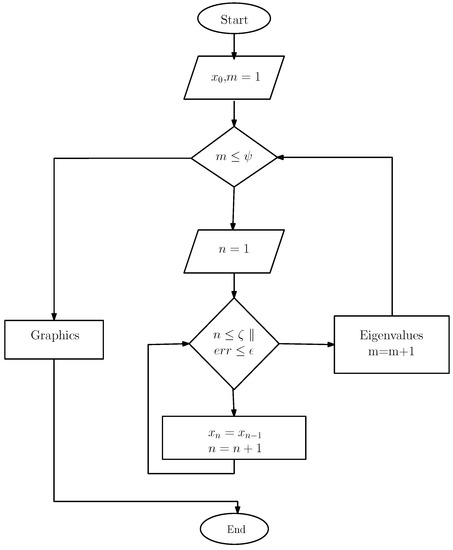
Figure 4.
Flow diagram for solving the nonlinear system.
5. Results and Discussion
Table 3 contains values that represent the relationship between the electrical equivalent load resistance and the turbine-PMSG rotational speed corresponding to 23 chosen iterations. As can be appreciated in Figure 5, there is a nonlinear, inverse relationship between the variables involved. Limits for the x-axis are .
Table 3.
Values associated with Figure 5.
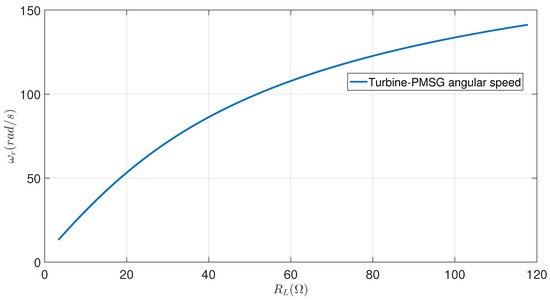
Figure 5.
Turbine-PMSG rotational speed as electrical equivalent load resistance function.
Table 4 contains values associated with the relationship between the 2N-MBC duty cycle and the Jacobian matrix determinant evaluated at the state state vector equilibrium point corresponding to 23 chosen iterations. As can be seen in Figure 6, the determinant increases as the number of duty cycles increases, so there is a nonlinear direct relationship between D and the Jacobian matrix determinant.
Table 4.
Values associated with Figure 6.
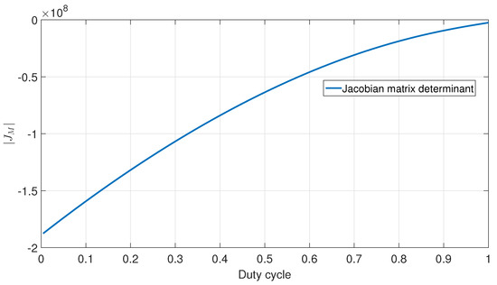
Figure 6.
Jacobian determinant as a function of electrical equivalent load resistance.
Table 5 shows the corresponding values between the electrical equivalent load resistance and the module of the state vector’s derivative. This table is relevant since it shows the absolute errors associated with different values of for the same number of iterations. As can be seen in Figure 7, there is an oscillating, increasing trend between and . The order of the absolute error is 10.
Table 5.
Values associated with Figure 7.
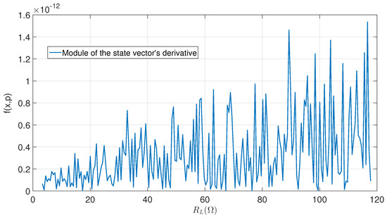
Figure 7.
Derivative magnitude as a function of electrical equivalent load resistance.
Table 6 indicates the corresponding values between the electrical equivalent load resistance and the tip speed ratio. The minimum and maximum values for are within a typical tip speed ratio range. Figure 8 shows a directly nonlinear relationship between and .
Table 6.
Values associated with Figure 8.
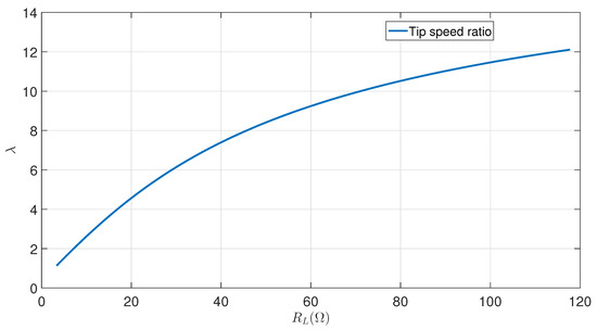
Figure 8.
Tip speed ratio as a function of electrical equivalent load resistance.
Table 7 is very important, since it indicates the values between the 2N-MBC duty cycle and the turbine-PMSG angular speed, demonstrating the inverse relationship between these two variables, which was one of the main goals of this research. Figure 9 shows the inverse nonlinear relationship between D and . The stator current in the original coordinates for phase “a” was calculated by Equation (16); then, three particular orbits were selected, as shown in Figure 9, to represent the current behavior. The red sine wave represents when , the green function is when , and the purple sine function shows when . It can be appreciated that the higher the value of D, the the lower frequency and higher amplitude of , as a consequence of a higher voltage in the 2N-MBC output terminals. Table 8 contains the corresponding values for the phase “a” stator currents in original coordinates for the three orbits previously described, and the 33 values of the time vector in the interval seconds.
Table 7.
Relationship data for turbine-PMSG angular speed and duty cycle.
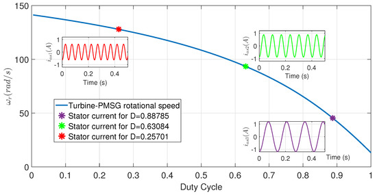
Figure 9.
Turbine-generator speed steady-state as a function of the duty cycle and three representative steady-state orbits in original coordinates.
Table 8.
Relationship data for phase A stator current in original coordinates and time for three specific values of duty cycle.
Table 9 presents the equilibrium points for different duty cycle values. For a particular D value, there are three elements for the equilibrium point; they are represented by three asterisks in Figure 10. Two are complex conjugate and one is located in the real axis. As can be seen, the bifurcation analysis shows that there is neither a saddle node, nor a pitchfork bifurcation, nor a transcritical bifurcation, nor a Hopf bifurcation occur, when the equivalent electrical load resistance is considered as the bifurcation parameter. This means that there is no eigenvalue for the Jacobian matrix evaluated in the equilibrium point for each duty cycle value that crosses the imaginary axis. As a result, the critical boundary in the parametric space is non-existent and the number of equilibria is constant. Besides, each equilibrium represented in Figure 10 is locally asymptotically stable, as all of the corresponding eigenvalues are always located on the open left half complex plane. It is important to note that the real axis in Figure 10 has a logarithmic scale.
Table 9.
Eigenvalues associated with different duty cycle values.
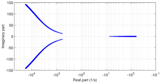
Figure 10.
Eigenvalues as the duty cycle is varied.
6. Conclusions
This research demonstrated a nonlinear inverse relationship between a 2N-MBC duty cycle and the turbine-PMSG rotational speed of a WECS. It was also concluded that for higher duty cycles, there will be smaller stator current frequencies and larger amplitudes. This is a logical fact because of the increasing voltage at the 2N-MBC output terminals. The steady-state analysis also showed that every eigenvalue of the linearized system was located in the left half of the complex plane; therefore, every equilibrium is locally asymptotically stable. It important to recall that the coefficient matrix of the linearized system is obtained by evaluating the Jacobian matrix at the nominal steady state point (equilibrium) for each particular duty cycle. In our case, eigenvalues never cross the imaginary axis of the complex plane; therefore, the number of equilibria never changes, and the bifurcation surface does not appear in the parametric space. The proposed model that represents the uncontrolled rectifier, the 2N-MBC, the three-phase inverter, and the three-phase load allowed the system to be simplified in order to obtain valuable results for pure resistive electric loads. In practice, nonlinear dynamic electric loads are usually connected to WECS, so different and further analysis will be carried out as future work.
Author Contributions
J.G.G.-H. contributed through investigation, validation, writing, reviewing, and editing. R.S.-C. contributed the conceptualization of the article, formal analysis, software, supervision, administration, and methodology. All authors have read and agreed to the published version of the manuscript.
Funding
This research received no external funding.
Institutional Review Board Statement
Not applicable.
Informed Consent Statement
Not applicable.
Data Availability Statement
Not applicable.
Acknowledgments
The authors would like to thank the support of the Tecnológico Nacional de México-Instituto Tecnológico de Ciudad Madero and Consejo Nacional de Ciencia y Tecnología during every stage of this research project.
Conflicts of Interest
The authors declare no conflict of interest.
Abbreviations
The following abbreviations are used in this manuscript:
| MBC | Multilevel Boost Converter |
| GW | Gigawatt |
| GWEC | Global Wind Energy Council |
| WECS | Wind Energy Conversion Systems |
References
- GWEC. Global Wind Report; Global Wind Energy Council: Brussels, Belgium, 2019; Available online: https://gwec.net/global-wind-report-2019/ (accessed on 15 July 2021).
- Reichenberg, L.; Wojciechowski, A.; Hedenus, F.; Johnsson, F. Geographic aggregation of wind power—An optimization methodology for avoiding low outputs. Wind Energy 2017, 20, 19–32. [Google Scholar] [CrossRef]
- Cirili, U.; Rotea, M.; Santoni, C.; Leonardi, S. Large-eddy simulations with extremum-seeking control for individual wind turbine power optimization. Wind Energy 2017, 20, 1617–1634. [Google Scholar] [CrossRef]
- Gebraad, P.; Thomas, J.; Ning, A.; Fleming, P.; Dykes, K. Maximization of the annual energy production of wind power plants by optimization of layout and yaw-based wake control. Wind Energy 2017, 20, 97–107. [Google Scholar] [CrossRef] [Green Version]
- Bastankhah, M.; Porté-Agel, F. Wind farm power optimization via yaw angle control: A wind tunnel study. J. Renew. Sustain. Energy 2019, 11, 23301–23312. [Google Scholar] [CrossRef] [Green Version]
- Sun, H.; Qiu, C.; Lu, L.; Gao, X.; Chen, J.; Yang, H. Wind turbine power modelling and optimization using artificial neural network with wind field experimental data. Appl. Energy 2020, 280, 115880. [Google Scholar] [CrossRef]
- Jiang, H.; Li, Y.; Cheng, Z. Performances of ideal wind turbine. Renew. Energy 2015, 83, 658–662. [Google Scholar] [CrossRef]
- Khamlaj, T.A.; Rumpfkeil, M.P. Analysis and optimization of ducted wind turbines. Energy 2018, 162, 1234–1252. [Google Scholar] [CrossRef]
- Cheng, M.; Zhu, Y. The state of the art of wind energy conversion systems and technologies: A review. Energy Convers. Manag. 2014, 88, 332–347. [Google Scholar] [CrossRef]
- Yaramasu, V.; Wu, B.; Sen, P.C.; Kouro, S.; Narimani, M. High power wind energy conversion systems: State-of-the-art and emerging technologies. Proc. IEEE 2015, 103, 740–778. [Google Scholar] [CrossRef]
- Nikolic, V.; Sajjadi, S.; Petkovic, D.; Shamshirband, S.; Cojbasic, Z.; Por, L.Y. Design and state of art of innovative wind turbine systems. Renew. Sustain. Energy Rev. 2016, 61, 258–265. [Google Scholar] [CrossRef]
- Nijiri, J.G.; Soffker, D. State of the art in wind turbine control: Trends and challenges. Renew. Sustain. Energy Rev. 2016, 60, 377–393. [Google Scholar] [CrossRef]
- Alhmoud, L.; Wang, B. A review of the state of the art in wind energy reliability analysis. Renew. Sustain. Energy Rev. 2018, 81, 1643–1651. [Google Scholar] [CrossRef]
- Gandomkar, A.; Parastar, A.; Jul-Ki, S. High-Power Multilevel Step-Up DC/DC Converter for Offshore Wind Energy Systems. IEEE Trans. Ind. Electron. 2016, 63, 7574–7585. [Google Scholar] [CrossRef]
- Thayumanavan, P.; Kaliyaperumal, D.; Subramaniam, U.; Bhaskar, M.S.; Padmanaban, S.; Leonowicz, Z.; Mitolo, M. Combined Harmonic Reduction and DC Voltage Regulation of A Single DC Source Five-Level Multilevel Inverter for Wind Electric System. Electronics 2020, 9, 979. [Google Scholar] [CrossRef]
- Bhupender, S.; Ratna, D.; Jayaram, N. Capacitor voltage balancing in cascaded H-bridge multilevel inverter and its modelling analysis for grid integrated wind energy conversion system application. Int. J. Circuit Theory Appl. 2019, 47, 1323–1339. [Google Scholar] [CrossRef]
- Yang, G.; Yi, H.; Chai, C.; Huang, B.; Zhang, Y.; Chen, Z. Predictive Current Control of Boost Three-Level and T-Type Inverters Cascaded in Wind Power Generation Systems. Algorithms 2018, 11, 92. [Google Scholar] [CrossRef] [Green Version]
- Bianchi, F.D.; De Batista, H.; Mantz, R.J. Wind Turbine Control Systems: Principles, Modelling and Gain Scheduling Design; Springer: London, UK, 2007. [Google Scholar]
- Wang, J.; Xu, D.; Wu, B.; Luo, Z. A Low-Cost Rectifier Topology for Variable-Speed High-Power PMSG Wind Turbines. IEEE Trans. Power Electron. 2019, 26, 2192–2200. [Google Scholar] [CrossRef]
- Chen, J.; Yao, W.; Zhang, C.K.; Ren, Y.; Jiang, L. Design of robust MPPT controller for grid-connected PMSG-Based wind turbine via perturbation observation based nonlinear adaptive control. Renew. Energy 2019, 134, 478–495. [Google Scholar] [CrossRef]
- Hu, L.; Xue, F.; Qin, Z.; Shi, J.; Qiao, W.; Yang, W.; Yang, T. Sliding mode extremum seeking control based on improved invasive weed optimization for MPPT in wind energy conversion system. Appl. Energy 2019, 248, 567–575. [Google Scholar] [CrossRef]
- Zhang, Z.; Zhao, Y.; Qiao, W.; Qu, L. A Space-Vector-Modulated Sensorless Direct-Torque Control for Direct-Drive PMSG Wind Turbines. IEEE Trans. Ind. Appl. 2014, 50, 2331–2341. [Google Scholar] [CrossRef]
- Gonzalez-Hernandez, J.G.; Salas-Cabrera, R. Wind Power Extraction Optimization by Dynamic Gain Scheduling Approximation Based on Non-Linear Functions for a WECS Based on a PMSG. Mathematics 2021, 9, 2028. [Google Scholar] [CrossRef]
- Watil, A.; El-Magri, A.; Raihani, A.; Lajouad, R.; Giri, F. Multi-objective output feedback control strategy for a variable speed wind energy conversion system. Int. J. Electr. Power Energy Syst. 2020, 121, 106081. [Google Scholar] [CrossRef]
- El-Magri, A.; Giri, F.; Besançon, G.; El-Fadili, A.; Dugard, L.; Chaoui, F.Z. Sensorless adaptive output feedback control of wind energy systems with PMS generators. Control Eng. Pract. 2013, 21, 530–543. [Google Scholar] [CrossRef] [Green Version]
- Sai-Manoj, P.; Vijayakumari, A.; Sasi, K.K. Development of a comprehensive MPPT for grid-connected wind turbine driven PMSG. Wind Energy 2019, 22, 732–744. [Google Scholar] [CrossRef]
- Haq, I.U.; Khan, Q.; Khan, I.; Akmeliawati, R.; Nisar, K.S.; Khan, I. Maximum power extraction strategy for variable speed wind turbine system via neuro-adaptive generalizaed global sliding mode controller. IEEE Access 2020, 8, 128536–128547. [Google Scholar] [CrossRef]
- Pang, J.; Chen, Y.; He, S.; Qiu, H.; Wu, C.; Mao, L. Classification of friction and wear state of wind turbine gearboxes using decision tree and random forest algorithms. J. Tribol. 2020, 143, 1–28. [Google Scholar] [CrossRef]
- Gong, Y.; Fei, J.L.; Tang, J.; Yang, Z.G.; Han, Y.M.; Li, X. Failure analysis on abnormal wear of roller bearings in gearbox for wind turbine. Eng. Fail. Anal. 2017, 82, 26–38. [Google Scholar] [CrossRef]
- Greco, A.; Mistry, K.; Sista, V.; Eryilmaz, O.; Erdemir, A. Friction and wear behaviour of boron based surface treatment and nano-particle lubricant additives for wind turbine gearbox applications. Wear 2011, 271, 1754–1760. [Google Scholar] [CrossRef]
- Li, X.; Zhang, X.; Jiang, W.; Wang, J.; Wang, P.; Wu, X. A novel assorted nonlinear stabilizer for DC-DC multilevel boost converter with constant power load in DC microgrid. IEEE Trans. Power Electron. 2020, 35, 11181–11192. [Google Scholar] [CrossRef]
- Kuncham, S.K.; Annamalai, K.; Nallamothu, S. New structure of single phase two stage hybrid transformerless multilevel PV inverter. Int. J. Circuit Theory Appl. 2019, 47, 152–174. [Google Scholar] [CrossRef] [Green Version]
- Gonzalez-Hernandez, J.G.; Salas-Cabrera, R.; Vazquez-Bautista, R.; Ong-de-la-Cruz, L.M. Method for maximum power point tracking and verification by modeling a unified wind energy conversion system. MethodsX 2021, 8, 101298. [Google Scholar] [CrossRef] [PubMed]
- Krause, P.; Wasynczuk, O.; Sudhoff, S.; Pekarek, S. Analysis of Electric Machinery; IEEE Press: New York, NY, USA, 2013. [Google Scholar]
- Khodabakhsh, J.; Mohammadi, E.; Moschopoulos, G. PMSG-based wind energy conversion systems integration into DC microgrids with a novel compact converter. IEEE Access 2020, 8, 83583–83595. [Google Scholar] [CrossRef]
- Gonzalez-Hernandez, J.G.; Salas-Cabrera, R. Representation and estimation of the power coefficient in wind energy conversion systems. Rev. Fac. Ing. 2019, 50, 77–90. [Google Scholar] [CrossRef] [Green Version]
Publisher’s Note: MDPI stays neutral with regard to jurisdictional claims in published maps and institutional affiliations. |
© 2022 by the authors. Licensee MDPI, Basel, Switzerland. This article is an open access article distributed under the terms and conditions of the Creative Commons Attribution (CC BY) license (https://creativecommons.org/licenses/by/4.0/).