Abstract
Understanding physical phenomena such as blast shock waves produced by controlled explosions are relevant for issues appearing in the fields of military and civilian activities. The current study analyzes detonations of cylindrical and 3D cone-shaped charges through experimental trials and numerical simulations. In order to accomplish such goals, the work is divided into three sections, which include (a) numerical studies on spherical charges to define an accurate model; (b) numerical and experimental studies to assess the influence of cylindrical and 3D cone-shaped charges on incident peak pressure and the shape of shock wave propagation; and (c) numerical studies to define the magnitude of incident peak pressure as a function of orientation, aspect ratio and scaled distance. Validation studies proved that the applied model was reasonably accurate. Furthermore, relevant findings included the observation that when the aspect ratio decreases, more release energy is concentrated in the axial direction for a 3D cone-shaped charge, while as the aspect ratio increases, more release energy is concentrated in the radial direction for a cylindrical-shaped charge. Additionally, the blast shock wave produced a great quantity of energy for the explosive charge with the largest surface. Finally, the orientation has less influence than the aspect ratio on the incident pressure contours. Therefore, cylindrical charges have the potential of inflicting great damage when used as confined charges, and 3D charges are able to cut solid materials in case of a direct contact.
MSC:
76L05
1. Introduction
A prison break recently occurred in the Ecuadorian coastal city of Guayaquil, as reported by a variety of mass media and the proper government [1,2,3]. This escape occurred due to the planting of explosive charges placed on drones, which detonated with a considerable magnitude. The explosion caused severe damage to the structure elements, breaching walls and roofs. Additionally, organized crime performed a terrorist attack on government facilities using a non-spherical type of explosive charge. Non-spherical-shaped charges release a large quantity of energy on a specific area, subsequently inflicting a great amount of damage on it. The affectations that were caused by the non-spherical explosive charge at the near-field include the cracking, spalling and fragmentation of concrete, large deformations or shears in the transversal and longitudinal steel bars, loss of concrete strength, breaching walls and in some cases, the demolition of structural elements, which may lead to a collapse of a given structure. Consequently, the national Bureau of Prisons demanded a guidance for improving the structural performance to be better prepared for further eventual attacks based on a variety of explosive materials. Therefore, in order to develop and design a sophisticated protective guidance, it is mandatory to characterize the blast shock wave in terms of incident peak pressure and net impulse as well as the determination of dynamic response of such structures and the subsequent impact on its final state of damage.
In this sense, the current study is the first of a set of studies that are part of an official national research project, which intends to provide information and design concepts for the improvement of the aforementioned structural performances of state facilities of strikes with explosive materials involved. Therefore, this initial research has been focused on the characterization of the blast shock waves generated by the detonation of cylindrical- and 3D cone-shaped charges, the results of which may be a constructive technical and blast engineering support through the understanding of the mathematical model that describes how the shock wave is propagated through the surrounding air.
2. Theory and Technical Context of Blast Shock Waves
An explosive is defined as a chemical substance with the capacity to react readily and subsequently release chemical energy stored in its molecular structure. The science of explosives comprises four specific events: ignition, the growth of deflagration (burning), the deflagration to detonation transition, and the propagation of detonation [4]. The intensity of the first three events depends on the stoichiometry and thermochemistry of the explosives. On the other hand, the fourth effect depends on fluid dynamics. A vast collection of observations regarding the analytical expressions of blast shock wave propagation has led to an advanced degree of documentation upon this issue.
Mespoulet et al. [5] and Hryciow et al. [6] exposed that a blast shock wave could be characterized if the explosive type, explosive weight, standoff distance, and explosive shape are known. The explosive type defines the chemical properties, while the weight infers the quantity of release energy. Furthermore, the standoff distance is directly related to the magnitude of the incident pressure and impulse, whereas the explosive shape is defined as a shock wave which is propagated through the surrounding air receding from the source of the explosion.
The present study commences the research with a literature review of existing methods of characterization of blast shock waves. In recent years, an immensely vast ssemblage of studies regarding the analytical methods for the characterization of blast shock waves produced by the detonation of spherical- (Figure 1a) and hemispherical-shaped explosive charges have been well documented and have been presented in manuals, codes, articles, and reports such as [7,8,9,10]. The theories and models developed in such a scenario are not applicable to characterize the blast shock waves generated by the detonation of non-spherical explosive shaped charges. This happens because the detonation and blast wave propagation of shaped charges are non-axisymmetric problems of thermochemistry and fluid dynamics [11].
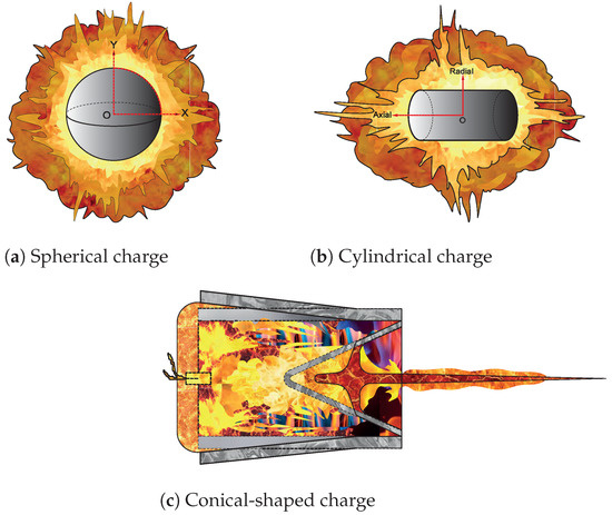
Figure 1.
Sketch of shapes of shock wave propagation.
Regarding cylindrical-shaped charges, Figure 1b, ref. [12] defined the incident peak pressure as a function of , where a is the radius of the cylinder and R is the distance from the axis. The results demonstrated that such a shape concentrates the effect of the explosive’s energy at the axial axis. Therefore, the incident peak pressure is higher for a cylindrical charge that an equivalent spherical charge at the near-field. However, it gradually adopts the values of a spherical charge when the shock wave moves away from detonation point. Some researchers have stated some empirical equations which define the incident peak pressure in terms of scaled distance Z and charge aspect ratio , e.g., ref. [13] ; ref. [14] for ; for ; ref. [15] ( 0.25, 0.5, 1, 2, 3, 4 and 6), where . Through graphs, Plooster et al. [16] depicted the incident pressure fluctuations for as function (0.25, 0.5, 1, 2, 3, 4 and 6) and angle orientation with intervals every . The results indicated that the method is only able to be applied at the far-field. Fan et al. [17] characterized the blast shock wave considering the influences of charge aspect ratio, orientation, and detonation configuration. The outcomes (incident peak pressure and impulse) are expressed as a function of scaled distance. Such research quantitatively reported the distribution of incident pressure, which was mainly concentrated along the axial axis direction. Additionally, the results yielded that the effects of a shaped charge have no influence for scaled distances greater than 2 at orientation relative to the axial axis direction, while the effects of an aspect ratio less than 2 have a significant impact on the incident peak pressure at 90° orientation. Gao et al. [18] stated the propagation of a blast shock wave in terms of pressure contours using the hydrocode AUTODYN. The contours are categorized into patterns and are analyzed in detail. Hereby, some three regions are identified, which are called axial, vertex and radial. The research introduces a term known as a bridge wave. This is the connection medium for linking the front waves produced by the flat and curved surfaces of a charge. The interaction of three waves leads to another wave and subsequently causes superposition effects. Therefore, an accurate mathematical model which comprises all effects is a significant challenge. However, it will certainly have an enormous contribution in blast engineering.
Rigby et al. [19] graphically represents a mass equivalence model between spherical and cylindrical-shaped charges through logarithmic interpolations of kinetic energy at the same scaled distance. The verification indicates that the accuracy of the model ranges between 4% and 10%. This is due to the condition of non-sphericity of a charge. The aforementioned studies shared a common criterion in that the pressure produced by cylindrical charges presents asymmetrical effects that are relatively more significant in the axial axis direction than in the radial axis direction and therefore are significantly higher for the widest surface area.
Furthermore, a conical-shaped charge is defined in geometrical terms as a 3D solid with rectangular or cylinder shapes with a negative conical cavity at one face [20,21]. Liu et al. [22] numerically characterized the blast effects produced by the detonation of a shaped charge with a conic and semi-elliptical cavity; see Figure 1c. The results allowed to observe that the explosive gases form a high-velocity jet. The jet formation is composed by two stages, of which the former appears when the release energy converges into the cavity, while the latter emerges when the energy gradually diverge as the jet moves away from the detonation point. Additionally, different cavity shapes lead jets to adopt different velocity distributions. Pyka et al. [23] studied the physical principles behind the mechanism of jet formation of a shaped charge. The morphology of the jet was stated through photo sequences. They demonstrated that the difference in velocity between the head and tail of the jet is directly related to the lengthening of the jet and consequently to the kinetic energy. Some studies have described the equations that govern the physical mechanism that describe the morphology of jet formation and how this may be solved mathematically in a variety of forms. Subsequently, the Jones–Wilkins–Lee (JWL) equation of state (EOS) of explosives is used for calculating the pressure of detonation products [24]. The Mie–Grüneisen equation of state (EOS) is often used for modeling condensed materials at high pressure [25]. The Johnson–Cook model is used for computing the material flow stress as a function of strain hardening, strain-rate hardening, and thermal softening [26]. Geum et al. [27] numerically dealt with the discontinuous interface of multiphase flow through the ghost fluid method. Additionally, sequence images captured the detonation wave propagation and also the interaction between the detonation wave and liner (metallic material), as well as the evolution of a metal jet. The most relevant finding is the emergence of a slug in the rear part on the liner.
Overall, numerical simulations have been developed using hydrocodes with the capability of simulating blast shock wave propagation. The most common commercial hydrocodes include Epic Dynamic Finite Element Code, LS-DYNA, Explicit Dynamic, Autodyn, Dytran, Nastran, Europlexus and Apollo Blast Simulator [28]. They have incorporated some discretization methods such as the Lagrange solver, Euler solver, arbitrary Lagrange–Euler (ALE) solver, multi-material ALE formulation (MM-ALE), computational fluid dynamics (CFD) and smooth particle hydrodynamic (SPH) solver [29]. Each one has certain advantages and also limitations. Several studies have been conducted in the field of shock wave propagation and the effects on materials using the different discretization methods such as performing numerical simulations of free-air explosion using the MM-ALE solver [30]. Furthermore, there are numerical and experimental validations of the dynamic pressure of a shock wave under a free-field blast loading ALE solver [31], using CFD solver for blast wave propagation under a structure [32], and shock wave propagation using the Euler solver [28,33,34].
According to a generalized view in given studies, there is still a strong lack of information about the characterization of blast shock wave propagation for a non-spherical charge at the near-field. In fact, the blast shock wave propagation for 3D cone-shaped charges (different from conical shaped charges) has not yet been characterized and is poorly understood.
3. Materials and Methods
The characterization of blast shock waves produced by cylindrical and 3D cone-shaped charges are studied experimentally and numerically. The former is conducted by the detonations of such charges on a blasting zone and recording the events by high-speed camera, while the latter is carried out using hydrocodes that are normally used on the prediction of fluctuation of incident peak pressure and impulse produced on shock wave propagation. Hereby, different parameters, such as type and weight of the explosive, orientation, scale distance, aspect ratio and mesh size, need to be considered.
3.1. Experimental Study
The conducted experimental test site’s blasting zone was formed from a crater with a depth of five meters and having a diameter of 18 m. Some fence posts were cemented into the ground, while additionally, a rope spider web was tightened. The explosive charge was positioned into a ceiling mount and subsequently positioned into the rope spider web. Finally, the priming charge was initiated.
Later, filmmaking equipment (Phantom v2512) was installed some thirty meters distant to the explosive charge. The set up was established with parameters such as an area field of view of 400 m, a resolution of 512 × 512 pixels, 4 K video recording at 75,000 fps, an interval of 13.32 and 32.41 mm of focal length. The explosive charge was detonated and subsequently recorded. Finally, digital images of each trial were processed. Due to the large amount of data generated, images were processed with specialized commercial software at two stages. Initially, images were processed using the Phantom Camera Control (PCC) commercial software, and then, the Phantom System Developer Kit (SDK) was used to create an interface between PCC and Matlab software. Finally, a code based on the artificial vision technique was developed to customize, track, analyze the movement as well as present the results of the output variable. The explosive used was a pentolite 50/50 (), which is a mixture of 50% pentaerythritol tetranitrate (PETN) and 50% trinitrotoluene (TNT) [35]. The charges used were spherical by validation of a mathematical model and cylindrical and 3D cone-shaped charges by characterization of the shock wave, as seen in Figure 2.

Figure 2.
Types of explosive charges.
3.2. Numerical Study
The fluid dynamic equations correspond to the Navier–Stokes equation and conservation of energy, which describe the space-time evolution of a blast wave and are extremely extensive to be solved in detail. Therefore, instead, two assumptions were realized: the blast wave should be considered as an axisymmetric problem, and the principle of superposition of waves should be avoided. The assumption that the shock front grows radially and symmetrically is only applicable on spherical charges, as illustrated in Figure 1a. Figure 1b,c indicates the evolution process of a shock wave for non-spherical-shaped charges after detonation. The waves adopt irregular forms in which the radius of the shock wave is a vector-valued function that directly depends on the orientation, aspect ratio and time. Subsequently, flow properties such as density, velocity, temperature, and pressure are described by fluid dynamic equations, which are expressed in terms of radius of shock wave and orientation. The other assumption has been previously extensively discussed. While the shock wave is moving, it almost always undergoes non-linear effects such as reflection, refraction, and diffraction. Therefore, the equations that govern the oblique regime need to be included to capture the non-linear effects.
The present research used a commercial hydrocode (Ansys-Autodyn). This selection was based on four parts. First, it includes the conservation equations (mass, momentum, and energy) that describe the dynamic of a continuous media in terms of displacement, velocity, and acceleration. Secondly, it contains the thermochemistry of explosives, which is modeled with the Jones–Wilkins–Lee (JWL) equation of state (2) and relates pressure to the density and internal energy [36]. Furthermore, it counts with the ideal-gas equation of state for air (3) and finally with the constitutive model (4), which relates stress to a combination of strain , strain rate effects , internal energy I, and damage D.
where is the material density, is the velocity, I is the specific internal energy, is the stress tensor, p is the pressure, a deviatoric part , is the external body forces per unit mass, and is the deviatoric strain rate [36].
In Equation (2), A, B, , and represent the input parameters, represents the initial ratio of the internal energy, and V represents the initial relative volume of the detonation products [37]. The characteristics of the TNT and pentolite 50/50 are listed in Table 1.

Table 1.
Characteristics of the explosives [38].
The air is treated as an ideal gas. The terms of Equation (3) are defined as: the ratio of the specific heat (), density (), initial density ( (kg/m)) and internal energy at ambient pressure, which is × (mJ/mm).
The constitutive model is defined by Equation (4).
The solution of Equations (1)–(4) needs to be solved in both space and time domains. The former is defined by different spatial discretizations, while the latter is achieved by an explicit time integration method. The present research uses the multimaterial Euler discretization method. This mainly consists of modelling materials as grids, in which individual elements can contain multiple materials of the hydrodynamic type. As time progresses, the properties of these flows, such as velocity, pressure, density, etc., are computed at the fixed points of the grid, whereas mass, momentum, and energy flow across cell boundaries to subsequently compute the new mass, pressure, velocity, energy, etc., of that cell. The mathematical procedure has been previously described in [39].
The explicit time integration method needs to ensure the stability and accuracy of the solution. Therefore, the hydrocode has to satisfy the Courant–Friedrichs–Lewy (CFL) condition (5). It implies that the shock wave must not travel further than the minimum distance between grid elements in a single time step.
The flow out boundary condition is also necessary in the code because it prevents the blast wave reflection at the border of the grid.
The numerical study is divided in three sections. The first is a set of 1D and 2D numerical studies on spherical charges to define an accurate model, which is validated through mesh refinement, empirical methods, and numerical uncertainty studies. The second section comprises numerical studies to assess the influence of cylindrical and 3D cone-shaped charges on the incident pressure, arrival time and shape of shock wave propagation. The third part includes numerical studies to define the magnitude incident pressure as a function of angle orientation, aspect radio and scaled distance.
Methodology
A set of six 1D simulations were extended with different mesh sizes of 2, 1, 0.5, 0.25, 0.1 and 0.067 mm to reach a high confidence level. The computational domain was based on a 1D wedge using a radial symmetric model (Figure 3a). The explosive charge was the spherical type. It had a radius of 33.57 mm, which is equivalent to 225 g of TNT. Flow properties were measured through the set of gauges, which were placed every 40 mm. Next, a set of six 2D simulations were performed. Subsequently, a comparison set of incident peak pressure histories between 1D and 2D model was extended to define a 2D numerical model with high convergence and optimal mesh size. The air domain used was a square of mm (Figure 3b). All the other parameters were equivalent to the previous analysis.
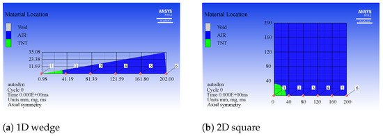
Figure 3.
1D and 2D numerical models.
Later, a set of three 2D simulations were performed with pentolite 50/50 charges of 450 g. The computational domain was based on a 2D square using an axially symmetric model and with a mesh size of 0.1 mm. The explosive charges were the spherical, cylindrical, and 3D cone types. Figure 4 illustrates the dimensions for each shape. Flow properties were measured through a set of gauges, which were placed every 120 mm at the abscissa and ordinate.
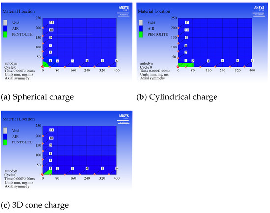
Figure 4.
2D Axially symmetric model.
Finally, a set of 2D simulations for spherical, cylindrical, and 3D cone charges were extended with a mass of 0.25, 0.5, 0.75, 1, 1.5, 2, 2.5, 3, 3.5, 4, 4.5 and 5 kg. They were conducted to collect pressure data in both space and time domains to trace the fluctuation of incident pressure as a function of angle orientation, aspect ratio, scaled distance, and shape of shock wave. Hereby, twelve simulations for spherical shaped charge were performed using TNT, while a total of thirty-six simulations for cylindrical ( = 3), ( = 5) and 3D cone ( = 0.625) shapes were performed using pentolite 50/50. Flow properties were measured through a set of gauges which were placed every fifteen degrees and every 50 mm (Figure 5).
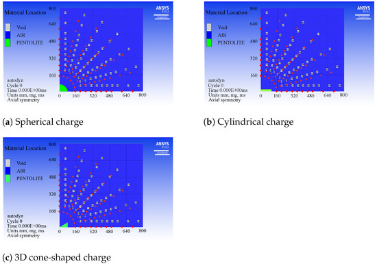
Figure 5.
2D numerical models.
3.3. Convergence Criteria
The quantification of numerical uncertainty is popular among studies in computational simulations journals [40,41,42].
The uncertainty of a CFD model is an estimation error involved in the numerical results. There is a consistent method called the grid convergence index that applies the generalized Richardson extrapolation theory. It uses the finest three meshes per size (fine, medium, and coarse) to determine a relative error. If its value is below 4%, it infers that the solutions calculated for the finest mesh slightly differ from the asymptotic value [43].
Equation (6) allows us to relate the mesh refinement ratio r with the fine and medium mesh size .
The order of convergence p could be obtained by Equation (7). The term f is the solution value of the numerical simulation for each mesh size. Refer to Table 2.

Table 2.
Pressure results of autodyn calculation for the near-field.
The GCI error is defined by Equation (9). Where is defined as the safety factor. It is 1.25 for three or more meshes [43], and is the relative error.
Equation (10) relates the GCI from fine to intermediate and from intermediate to coarse grid to define the asymptotic range [40].
4. Results and Discussion
4.1. 1D Analysis for Spherical Charge
Figure 6 illustrates incident pressure histories for 1D analysis and gives important remarks. Hereby, the empirical method (Kingery–Bulmash equation) can only be used for distances over 160 mm. The highlighted results in Table 2 lists that the convergence order at the vicinity of detonation requires a tiny mesh size due to its sensitivity. Therefore, it is necessary to use a mesh size of 0.1 mm to capture the blast wave for distances below 40 mm. It infers directly with high computational requirements.
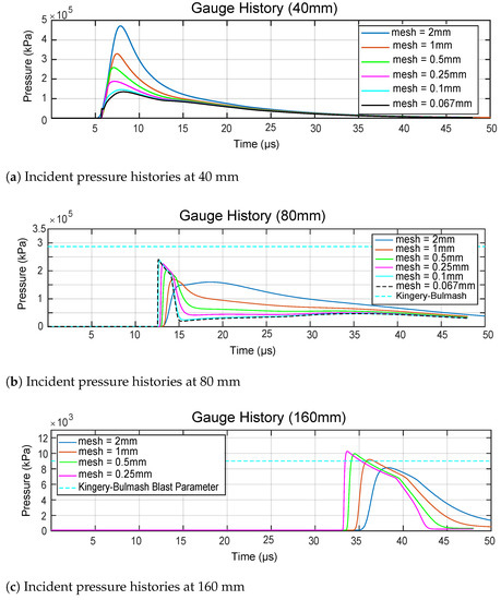
Figure 6.
Near-field incident pressure histories for a spherical charge of 225 g of TNT.
4.2. Convergence Criteria
The GCI method was developed from the pressure values obtained from the numerical simulations for the three finest mesh sizes, which are 0.25, 0.1 and 0.067 mm (Figure 7). This lists the asymptotic solution and the asymptotic range. The abscissa of Figure 7 is formed by the mesh size as it approaches zero and the other mesh sizes. The ordinate of Figure 7 represents the asymptotic solution and the pressure values obtained from the three mesh sizes. Additionally, this analysis was performed for distances of 40, 80, 120 and 160 mm from the detonation point. Hereafter, these distances are referred to as gauge 2, gauge 3, gauge 4, and gauge 5, respectively. The GCI represents a relative error bound. Figure 7 lists , where reaches a percentage of less than 0.6% and the asymptotic range approaches 1 for gauge 2, 3 and 4. This means that the numerical analysis has reached a high convergence for mesh sizes of less than 0.067 mm. Even though the system corresponds to a chaotic type of system at the vicinity of the detonation point, gauge 1 has reached an acceptable convergence. This conclusion considers that the asymptotic range is 0.925 and is 3.61%. This can be confirmed through the slope of the first two points illustrated in Figure 6, which represents the difference between the finest solutions and the solution with a mesh size of 0.
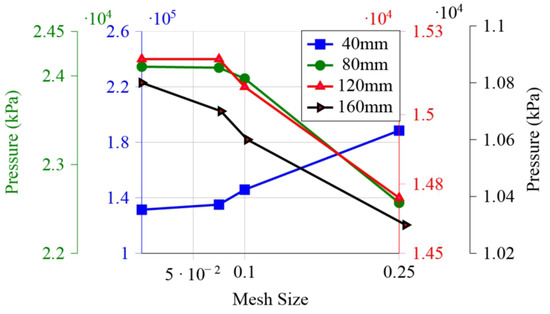
Figure 7.
Calculation of grid convergence index for near-field.
4.3. 2D Analysis for Spherical Charge
The study compared incident pressure histories between 1D and 2D analysis (Figure 8). As per the criterion of superposition of curves drawn, the 2D model appears to be accurate. Thus, the mesh size for 2D model is 0.1 mm for distances lower than 40 mm and 1 mm for distances higher than 40 mm.
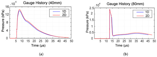
Figure 8.
Convergence analysis between 1D and 2D. (a) Incident pressure histories at 40 mm [44], (b) Incident pressure histories at 80 mm.
4.4. Shaped Charge Analysis
Figure 9 depicts the results of image processing in terms of change of light area and exposition time. They illustrate that the exposition time is the fastest for 3D conic-shaped charges and slowest for spherical charges, while the area of combustion behind the shock wave reaches higher values for spherical charges and lower values for 3D conic-shaped charges. Therefore, the geometrical propagation of combustion behind the shock wave may be directly related to the shock wave propagation, as indicated in the numerical results.
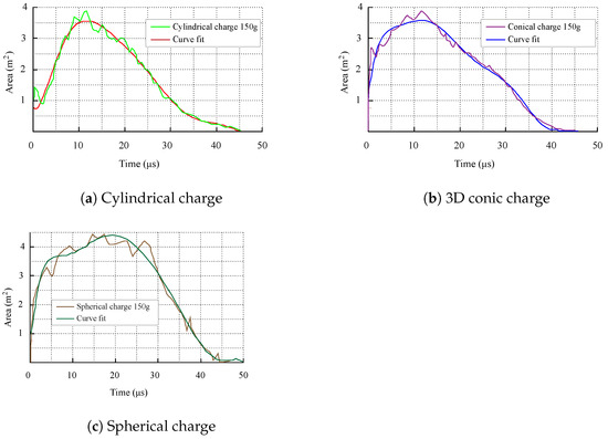
Figure 9.
Area of combustion behind the shock wave.
The images obtained from high-speed cameras (Figure 10, Figure 11 and Figure 12) contain a type of disturbances called noise. Noise is generated due to blasting zone environment conditions such as dust as well as wind effects. Therefore, some noise filters were developed through algorithms to improve image quality and accuracy.
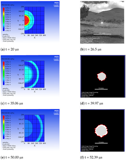
Figure 10.
Numerical and experimental results for spherical charge of 150 g of pentolite.
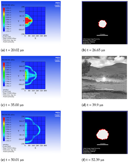
Figure 11.
Numerical and experimental results for a cylindrical charge of 150 g of pentolite.
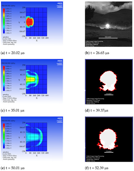
Figure 12.
Numerical and experimental results for 3D cone charge of 150 g of pentolite [44].
4.4.1. Spherical Charge
Numerical calculations indicate that the incident pressure at the front of the shock wave is a function of the radial distance. The shock wave expands uniformly through the surrounding air in the form of concentric circles, whereas the schlieren and shadowgraph images obtained demonstrate that the shock wave expands as a shadow ball (Figure 10). Other fundamental findings include that the incident peak pressure at the front of the shock wave in the radial direction reaches its highest magnitude at 20.10 s , which then gradually diminishes (Figure 13). Furthermore, we encountered that spherical-shaped charges produce the fastest-travelling shock waves in the radial axis.
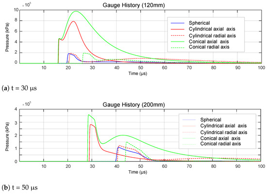
Figure 13.
Incident peak pressure histories for 150 g of pentolite.
Figure 10b demonstrates the ignition process, while Figure 10d,f indicate the growth of deflagration (burning). The detonation close-ups clearly illustrate that it expands in form of concentric circles. Therefore, a combustion model can further be proposed, which should include equation of state, equations for sphere and dimensional analysis based on the images obtained.
4.4.2. Cylindrical Charge
Numerical calculations yielded that the shock wave non-uniformly expands through the surrounding air. Such a shock wave adopts two well defined forms, an oblate spheroid, which is formed at the rear, and a bullet, which is formed at the front. Within the given experimental results, the schlieren and shadowgraph images indicate that the shock wave expands as a shadow ball until 26.65 s. After this time, it tends to adopt an elliptical shape (Figure 11). Similarly, the incident peak pressure in the axial direction () is greater than in the radial direction (), while the release energy is more concentrated in the axial direction. Additionally, we have realized that the shock wave travels faster in the axial direction and that the history at 200 mm demonstrates the presence of a secondary shock in the radial direction at approximately 50 s (Figure 13).
Shadowgraph images depict the morphology of the combustion process. First, the energy is released in the form of heat. Later, it expands as function of the shape of the charge. In other words, as the curved face of the charge is greater than the planar face, the heat distribution is greater in the curve face than the planar face (Figure 11b,d,f). Therefore, it has a direct relationship with the shock wave propagation as the hydrodynamic regime completely predominates just after deflagration, and its initial boundaries are taken from the combustion process.
4.4.3. 3D Conic Charge
Numerical calculations yielded that the shock wave non-uniformly expands through the surrounding air. The shock wave first adopts a vertical ellipse contour until 20 s (Figure 12). After this time, it adopts a symmetric jellyfish dome-type profile. Other essential findings include that the incident peak pressure in the axial direction is greater than in the radial direction, while both axes present secondary shocks. Furthermore, the shadowgraphs (Figure 12b,d,f) must rotate 90 degrees clockwise to allow a comparison.
On the other hand, the schlieren and shadowgraph images obtained from the experimental results generated a shadow ellipse that later adopts a domed shape, equivalent to those of the numerical results. The lightest gray color refers to how the evolution of pressure distributes, while the darkest gray color refers to the combustion process (Figure 12b,d,f). Therefore, such a distribution, being sharp-shaped at the corner. infers that the release energy is mostly concentrated in the axial direction.
4.5. Blast Parameters for the Positive Phase
The present study allowed us to realize that there is a superposition of the curve depicted in the Kingery–Bulmash blast parameters and the results obtained from the numerical simulation (Figure 14). This indicates that both curves keep the same tendency of the incident pressure as a function of the scaled distance. However, the Kingery-Bulmash blast parameters are more conservative with an increase by a factor of 1.67, as also indicated by previous studies where a factor of 1.65 was obtained [43]. This demonstrates that this study’s computational model provides an acceptable confidence, and subsequently, it can be applied to other shaped charges.
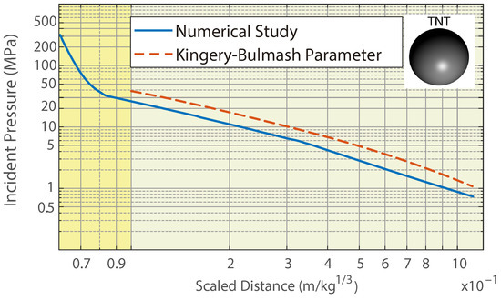
Figure 14.
Comparison between Kingery–Bulmash blast parameters and numerical simulations for TNT spherical free-air charges.
4.6. Influence of the L/D Aspect Ratio, Scaled Distance and Orientation
The propagation of a blast shock wave for a cylindrical-shaped charge with an and and a 3D conic-shaped charge with an is illustrated (Figure 15). Hereby, the incident peak pressure at the axial axis reaches the highest magnitudes for cylindrical charges with and the lowest for cylindrical charges with (Figure 15a). The incident peak pressure at the axial axis reaches the highest magnitude for 3D conic charges and the lowest for cylindrical charges with (Figure 15b,c). The for cylindrical charges has no effect for distances over 500 mm at the axial axis. The incident peak pressure at the radial axis at all distances is higher for cylindrical charges with and lower for 3D conic charges. Additionally, results indicate that the incident peak pressure at the axial axis is concentrated at 0 to 5 degrees for cylindrical charges and at 0 to 15 degrees for 3D conic charges.
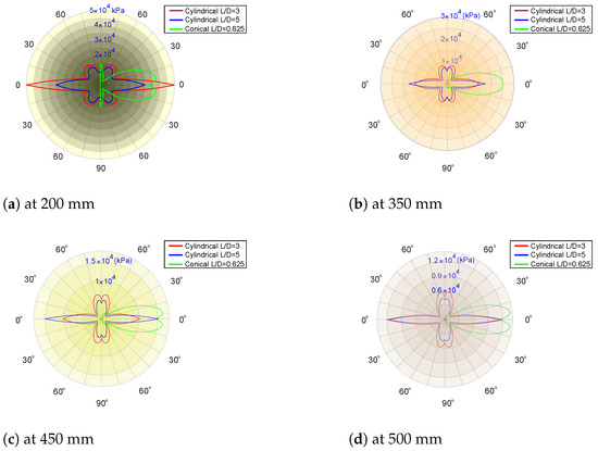
Figure 15.
The incident pressure vs. angle orientation for 0.5 kg of pentolite 50/50.
With the characterization of a blast wave for pentolite for cylindrical and 3D conic-shaped charges, the current study demonstrates the change of incident peak pressure on cylindrical-shaped charges as a function of angle orientation and scaled distance for cylinder ratios of and 5 (Figure 16a,b) and for a 3D conic ratio of (Figure 17). Results for cylindrical-shaped charges yielded that the incident peak pressure reaches its highest magnitude at 0 degrees for both ratios. However, the principal limitation is that the incident peak pressure could not be obtained for a scale distance of less than for and for . This limitation is related to the inaccuracy of incident peak pressure at that range. The effect of over incident peak pressure can only be observed at 0 and 15 degrees, whereas the incident peak pressure at 45, 60, 75 and 90 degrees has its own tendency against the scaled distance, while the angle orientation does not have much influence on the incident peak pressure. Regarding 3D conic shaped charges, the incident peak pressure reaches its highest magnitude at 30 degrees. However, the incident peak pressure for 0, 15 and 30 degrees could not be obtained for a scale distance of less than . Lastly, the effect of 3D conic geometry over incident peak pressure can only be observed at 0, 15 and 30 degrees.
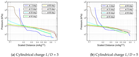
Figure 16.
Comparison of incident pressure vs. scaled distance for cylindrical charges.
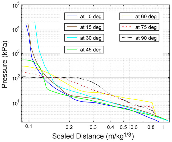
Figure 17.
Comparison of incident pressure vs. scaled distance for 3D conic charge = 0.625.
In general terms, the shaped charge and L/D aspect ratio utterly define the inception and evolution of the blast wave because it defines the vector-valued function of the radius of the shock wave at the near-field. The Schlieren and shadowgraph images evidence that such a function is directly related to energy concentration, and it depends on the face area of charge, being predominant within the largest area.
5. Conclusions
The predominant objective of the present research was to predict the effects generated by the detonation of cylindrical and 3D cone-shaped charges of pentolite 50/50 to define the fluctuation of incident peak pressure as a function of orientation, aspect ratio, scaled distance, and shape of shock wave. For this purpose, a set of two-dimensional numerical models were used to compare the incident peak pressure from 3D cone explosives from cylindrical explosives with different aspect ratios. Subsequently, a set of experimental trials were conducted at a blasting zone. Moreover, the multimaterial Euler method was verified by comparing with the test results. Then, the shape of shock wave caused by 3D cone and cylindrical explosives with different ratios were compared and discussed. This has led to several conclusions:
- The aspect ratio of the cylindrical and 3D cone-shaped charge have a significant effect on the inception, evolution, shape, propagation of the blast shock wave and incident peak pressure. As the aspect ratio decreases, more release energy is concentrated in the axial direction for a 3D cone-shaped charge, while as the aspect ratio increases, more release energy is concentrated in the radial direction for a cylindrical-shaped charge. The incident peak pressure follows the same previous analysis, but it decreases in the other direction. At an equivalent weight, the incident peak pressure caused by a 3D conic-shaped charge reaches higher values than a cylindrical charge. Therefore, the effect of a cylindrical-shaped charge could be considered for confined areas, while 3D conic shaped-charges could be considered for cutting purposes in the axial direction.
- From the experimental and numerical results, we realized that the orientation has less influence than the L/D aspect ratio on the incident pressure contours. However, it defines the vector-valued function of the radius of ashock wave in its early stage. The influence range on the incident pressure contours is from 0 to 5 degrees for cylindrical charges and from 0 to 30 degrees for 3D cone charges. In other words, cylindrical and 3D conic charges amplify their damage effect for such ranges, respectively.
- One of the challenges in the numerical simulation was to determine the effects caused by released energy in heat form. Typically, these data are simulated through an afterburn energy model which must be associated with chemistry. Unfortunately, this model is not available in the Autodyn hydrocode. Therefore, some non-linear effects caused by afterburn energy could not be simulated by numerical studies.
- The quantification of the magnitude of non-linear effects such as the reflection, refraction, and diffraction is an essential stage for providing full understanding of inception and evolution of a blast shock wave caused by cylindrical and 3D cone-shaped charges. Hereby, the results presented, which are mostly based on the hydrodynamic regime where radiation becomes less important, capture the superposition of waves. The image sequences indicate the presence of bridge waves which rarely emerge following a pattern. Subsequently, the results also yield the interaction between bridge waves and primary waves. It leads to a secondary shock wave. These facts allow the characterization of a blast shock wave for non-spherical charges significantly more complex than those by spherical charges. Therefore, compressible multiphase flows should be developed and incorporated into the Autodyn hydrocode in order to deal with discontinuous interfaces.
Author Contributions
N.M.: Conception and design of study, Acquisition of data, Analysis and/or interpretation of data, Writing—original draft, Writing—review & editing. R.M.: Acquisition of data, Analysis and/or interpretation of data, Writing—original draft. T.T.: Writing—review & editing. All authors have read and agreed to the published version of the manuscript.
Funding
This research received no external funding.
Institutional Review Board Statement
Not applicable.
Informed Consent Statement
Not applicable.
Data Availability Statement
All the data and models employed and/or generated during the study appear in the submitted article.
Acknowledgments
We gratefully acknowledge the financial support provided by our university and the valuable support received from ESPE’s Innovative Public Company, the Operations Department of the Defense High Command, and the Scientific and Technological Research Center of Army (CICTE). We are grateful to Fernando Olmedo, Julio Ortiz, Edison Morales, Patricio Navia, Esteban Vasconez, Tatiana Almeida, Andres Sarango, Rodrigo Tapia, Klever Madrid, David Zapata, Rashid Salazar, Mireya Paredes and Sebastian Cajas for their contribution during the experimental phase of the current study.
Conflicts of Interest
In the case of the submitted manuscript entitled “Characterization of Blast Wave Parameters for Cylindrical and Conical Explosive Charges Close to the Detonation Point” authored by Nestor Mejía, Rodrigo Mejía, Theofilos Toulkeridis, we declare that we ensure that our manuscript has not been submitted simultaneously for publication anywhere else, containing original data and a paper with all its content (not even partially) not presented previously in any journal, symposium or congress. Additionally, we do not have any material (figures, images or tables) included in the manuscript that may require to obtain a permission to reproduce copyrighted material from other sources. There is no conflict of interest with any party and there is no problem with the ethical standards of any kind. Therefore, we are able and willing to sign an agreement for transfer of copyright to the publisher the moment our manuscript is accepted for publication.
References
- Ataque Con Drones en la Penitenciaría de Guayaquil. Available online: https://www.expreso.ec/actualidad/explosiones-posible-drones-carcel-maxima-seguridad-guayaquil-111763.html (accessed on 13 September 2021).
- Reportan Ataque con Drones a cáRcel en Guayaquil, Ecuador. Available online: https://www.telesurtv.net/news/ecuador-reportan-ataque-drones-carcel-guayaquil-20210913-0016.html (accessed on 13 September 2021).
- Drones Atacan Penal de máXima Seguridad de Ecuador. Available online: https://www.vozdeamerica.com/a/drones-atacan-penal-maxima-seguridad-ecuador/6225705.html (accessed on 13 September 2021).
- Zhao, Y.; Cao, W.; Huang, F.; Han, Y.; Long, X. Evaluation of detonation performance and working capacity of explosives by optimized VLW EOS. Combust. Flame 2022, 235, 111734. [Google Scholar] [CrossRef]
- Mespoulet, J.; Plassard, F.; Hereil, P.; Lefrançois, A. Influence of HE shape on blast profile. In Proceedings of the 8th European LS-DYNA Users Conference, Strasbourg, France, 24 May 2011. [Google Scholar]
- Hryciow, Z.; Borkowski, W.; Rybak, P.; Wysockiois, Z. Influence of the shape of the explosive charge on blast profile. J. KONES 2014, 4, 169–176. [Google Scholar] [CrossRef]
- Castellano, A.; Caltagirone, J. TM5-1300, Structures to Resist Accidental Explosions. In Contents of Structures to Resist the Effects of Accidental Explosions (TM 5-1300, NAVFAC P-397, AFM 22); Department of Army Navy NAVFAC (Naval Facilities) P-397, Air Force Regulation 88-2; Department of Defense Explosives Safety Board: Alexandria, VA, USA, 1990; pp. 369–388. [Google Scholar]
- Castellano, A.; Caltagirone, J. Design and Analysis of Hardened Structures to Conventional Weapons Effects. In Contents of Structures to Resist the Effects of Accidental Explosions (TM 5-1300, NAVFAC P-397, AFM 22); U.S. Army Corps of Engineers, UNIFIED FACILITIES CRITERIA (UFC): Washington, DC, USA, 2002; pp. 254–268. [Google Scholar]
- Department of Army Navy. Structures to Resist the Effects of the Accidental Explosions. Int. J. Trend Sci. Res. Dev. 2019, 3, 6–8. [Google Scholar]
- Hyde, D. Fundamentals of Protective Design for Conventional Weapons. In User’s Guide for Microcomputer Programs ConWep and FunPro, Applications of TM 5-855-1; U.S. Army Corps of Engineers, UNIFIED FACILITIES CRITERIA (UFC): Washington, DC, USA, 1988. [Google Scholar]
- Selivanov, V.; Fedorov, S.; Babkin, A.; Bolotina, I. Using shaped charges with a “magnetic cut-off” for testing anti-meteoroid shields. Acta Astronaut. 2021, 180, 170–175. [Google Scholar] [CrossRef]
- Cole, R. Underwater Explosions; Princeton University Press: Princeton, NJ, USA, 1948; pp. 63–78. [Google Scholar]
- Stoner, R.; Richard, G.; Bleakney, W. The attenuation of spherical shock waves in air. J. Appl. Phys. 1948, 9, 670–678. [Google Scholar] [CrossRef]
- Knock, C.; Nigel, D. Predicting the peak pressure from the curved surface of detonating cylindrical charges. Propellants Explos. Pyrotech 2011, 3, 203–209. [Google Scholar] [CrossRef]
- Swisdak, M. Explosion effects in air. In Explosion Effects and Properties: Explosion Effects in Air; Naval Surface Weapons Center: Maryland, MD, USA, 1975; pp. 120–128. [Google Scholar]
- Plooster, M.N. Blast effects from cylindrical explosive charges: Experimental measurement. In Defense Technical Information Center; U.S. Departament of Defense: Washington, DC, USA, 1982. [Google Scholar]
- Fan, Y.; Chen, L.; Li, Z.; Xiang, X.; Fang, Q. Modeling the blast load induced by a close-in explosion considering cylindrical charge parameters. Def. Technol. 2022. [Google Scholar] [CrossRef]
- Gao, C.; Zhen, X.; Fang, Q.; Hong, J.; Wang, J. Numerical investigation on free air blast loads generated from center-initiated cylindrical charges with varied aspect ratio in arbitrary orientation. Def. Technol. 2021. [Google Scholar] [CrossRef]
- Rigby, S.; Osborne, C.; Langdon, L.; Cooke, S.; Pope, D. Spherical equivalence of cylindrical explosives: Effect of charge shape on deflection of blast-loaded plates. Int. J. Impact Eng. 2021, 155, 103892. [Google Scholar] [CrossRef]
- Yadav, H.; Gupta, N. Study of collapse of a free surface conical cavity due to a plane or spherical shock wave. Int. J. Impact Eng. 1985, 3, 217–232. [Google Scholar] [CrossRef]
- Xu, S.; Zheng, W.; Shao, X.; Cheng, W. Numerical method for predicting the blast wave in partially confined chamber. Math. Probl. Eng. 2018. [Google Scholar] [CrossRef] [Green Version]
- Liu, M.; Liu, G.; Lam, K.; Zong, Z. Meshfree particle simulation of the detonation process for high explosives in shaped charge unlined cavity configurations. Shock Waves 2003, 6, 509–520. [Google Scholar] [CrossRef]
- Pka, D.; Bocian, A.; Bajkowski, M.; Magier, M. Numerical and experimental studies of the ŁK type shaped charge. Appl. Sci. 2020, 10, 6742. [Google Scholar] [CrossRef]
- Wang, Y.; Xu, Z.; Jin, Y.; Zhen, J. The effect of cylindrical liner material on the jet formation and penetration capability of cylinder-cone-shaped charge. Materials 2022, 15, 3511. [Google Scholar] [CrossRef]
- Heuzé, O. General form of the Mie–Grüneisen equation of state. C. R. Mécanique 2012, 340, 679–687. [Google Scholar] [CrossRef]
- Shi, J.; Xiang, Z.; Zu, X.; Xiao, Q. Experimental and numerical investigation of jet performance based on Johnson-Cook model of liner material. Int. J. Impact Eng. 2022, 170, 104343. [Google Scholar] [CrossRef]
- Geum, Y. Numerical simulation of conical and linear-shaped charges using an Eulerian Elasto-Plastic Multi-Material Multi-Phase Flow model with detonation. Materials 2022, 15, 1700. [Google Scholar]
- Sherkar, P.; Shin, P.; Whittaker, A. Influence of Charge Shape and Point of Detonation on Blast-Resistant Design. J. Struct. Eng. 2015, 2, 04015109. [Google Scholar] [CrossRef]
- Hofreiter, L.; Berezutskyi, V.; Figuli, L. Soft Target Protection Theoretical Basis and Practical Measures. Soft Target Prot. 2015. [Google Scholar] [CrossRef]
- Hashemia, S.; Bradford, M. Numerical simulation of free-air explosion using LS-DYNA. Appl. Mech. Mater. 2014, 1, 780–785. [Google Scholar] [CrossRef]
- Wang, I. Simulation and experimental validation of the dynamic pressure of shock wave under free-field blast loading. J. Vibroeng. 2014, 7, 3547–3556. [Google Scholar]
- Sohaimi, A.; Arif, S.M.; Ishak, A. Using computational fluid dynamics (CFD) for blast wave propagation under structure. Procedia Comput. Sci. 2016, 1, 1202–1211. [Google Scholar] [CrossRef]
- Fedora, N.; Valge, S. Simulation of blast action on civil structures using ANSYS Autodyn. In Proceedings of the AIP Conference Proceedinge, Moscow, Russia, 3 July 2016. [Google Scholar]
- Xue, Q.; Li, S.; Xin, C.; Shi, L. Modeling of the whole process of shock wave overpressure of free-field air explosion. Def. Technol. 2016, 5, 815–820. [Google Scholar] [CrossRef]
- Dobratz, B.M. Physical properties. In Properties of Chemical Explosives and Explosive Simulants; Lawrence Livermore Laboratory: Livermore, CA, USA, 1972. [Google Scholar]
- Collins, G.; Imperial College London, London, UK. Applied Modelling and Computation Group. Personal communication, 2002. [Google Scholar]
- Chang, B.H.; Yin, J.P.; Cui, Z.; Liu, T. Numerical simulation of modified low-density jet penetrating shell charge. Def. Technol. 2015, 3, 426–437. [Google Scholar] [CrossRef]
- Meyers, M. Dynamic Behavior of Materials; John Wiley & Sons: Hoboken, NJ, USA, 1994; p. 240. [Google Scholar]
- Anderson, D.A.; Tannehill, J.C.; Pletcher, R.H. Mathematical procedure. In Computational Fluid Mechanics and Heat Transfer; Taylor & Francis: Abingdon, UK, 2020. [Google Scholar]
- Kwasniewski, L. Application of grid convergence index in FE computation. Bull. Pol. Acad. Sci. Tech. Sci. 2013, 1, 123–128. [Google Scholar] [CrossRef]
- Karimi, M.; Akdogan, G.; Dellimore, K.H.; Bradshaw, S.M. Quantification of numerical uncertainty in computational fluid dynamics modelling of hydrocyclones. Comput. Chem. Eng. 2012, 43, 45–54. [Google Scholar] [CrossRef]
- Roach, P. Quantification of Uncertainty in Computational Fluid Dynamics. Annu. Rev. Fluid Mech. 1997, 1, 123–1260. [Google Scholar] [CrossRef]
- Paudel, S.; Saenger, N. Grid refinement study for three dimensional CFD model involving incompressible free surface flow and rotating object. Comput. Fluids 2017, 143, 123–134. [Google Scholar] [CrossRef]
- Mejia, N.; Peralta, R.; Tapia, R.; Duran, R. Damage assessment of RC columns under the combined effects of contact explosion and axial loads by experimental and numerical investigations. Eng. Struct. 2022, 254, 113776. [Google Scholar] [CrossRef]
Publisher’s Note: MDPI stays neutral with regard to jurisdictional claims in published maps and institutional affiliations. |
© 2022 by the authors. Licensee MDPI, Basel, Switzerland. This article is an open access article distributed under the terms and conditions of the Creative Commons Attribution (CC BY) license (https://creativecommons.org/licenses/by/4.0/).