Abstract
This paper addresses the issue of a complex three-dimension (3-D) terminal guidance process that is used against maneuvering targets while considering both the terminal impact angle (TIA) and field-of-view (FOV) angle constraints. According to the highly coupled and nonlinear 3-D terminal guidance model, an adaptive back-stepping sliding-mode guidance law algorithm is proposed in order to guarantee the stability and robustness of the guidance system. Considering the explicit expression of the line-of-sight (LOS) angle in the kinematics and dynamics of the terminal guidance process, the TIA constraint is transformed into an LOS constraint based on their well-known relationship. In view of the challenges in obtaining the motion information of maneuvering targets, an adaptive law design is introduced in order to estimate and compensate for external disturbances caused by the maneuvering of the target and modeling uncertainty. In addition, because the FOV angle represented by the overall leading angle is not a state variable in the sliding-mode guidance system, it is decoupled into two partial leading angles based on a specific transformation relation, so the 3-D terminal guidance control problem is converted into separate tracking system control issues in the pitch and yaw planes. Then, the Lyapunov stability theory is utilized to substantiate the stability of the guidance system, where the Lyapunov functions in both of the subsystems consist of the LOS and partial FOV state error terms. Finally, a series of simulations of various motion states of maneuvering targets under different terminal cases were carried out. It was proved that the terminal guidance design based on the strategies presented above was able to obtain the desired LOS constraints with satisfying the FOV limitation, and the simulation results verified the effectiveness, universality, and significance for practical applications of the proposed guidance design method.
1. Introduction
As an emerging type of weaponry with the ability to precisely strike high-value targets, terminal precision guidance technology for loitering munitions is gradually developing, and the design of the guidance law plays a key role. According to the action mechanism and characteristics of the general warhead that is loaded into the loitering munition, a strict TIA constraint is required to inflict the maximum damage on a typical target. Moreover, the photoelectric seeker of a loitering munition undertakes both reconnaissance and guidance functions. The locations and restricted detection zones of the optical assembly further introduce an FOV constraint into the system. Therefore, as this is a multiple-constraint guidance issue, it is necessary to design a novel advanced guidance law while considering both the TIA and FOV limitations.
The original research on the classical guidance law began with proportional navigation (PN), where the rotational angular velocity of the velocity vector in space is always proportional to that of the line of sight (LOS) during the process of approaching the target. Owing to its effectiveness and simplicity of implementation, the PN method has been widely used in homing guidance laws for practical engineering applications. However, when faced with the TIA constraint, the conventional PN guidance strategy cannot effectively solve the problem. A series of improved PN methods for striking and intercepting a target at a desired impact angle have emerged [1,2]. Pang et al. [3] designed a biased PN guidance law for infrared-guided munitions that were used against non-maneuvering targets on a surface while considering the impact angle constraint. A modified biased PN method was also applied in order to attack stationary and non-maneuvering targets, resulting in an expansion of the application range of the PNG method [4,5,6]. Nevertheless, the accurate maneuvering information of targets is required in order to produce guidance commands, but it is challenging to obtain.
With the development of modern control and strategic theories, the design of guidance laws for attacks on large maneuvering targets has an opportunity for development. A large number of new guidance laws based on modern control theory have been emerging. At present, modern guidance laws are mainly represented by the optimal guidance law, differential guidance law, and guidance law based on robust control theory.
The optimal guidance law involves the implementation of the optimal guidance strategy according to a given performance index; it was first used by Bryson to illustrate the optimality of explicit guidance [7]. It not only considers the dynamic relationship between a missile and its target, but also restricts the starting point or the ending point of the guidance, such as with the minimum terminal miss distance, the shortest guidance time, the lowest energy consumption, and the attack angle constraint [8,9]. Banerjee et al. [10] proposed an optimal guidance strategy that was solved with Legendre’s pseudo-spectrum method while considering the contradiction between the minimum energy consumption and shortest interception time in the process of ammunition guidance. Park et al. [11] proposed an optimal guidance law restricted by the FOV limit of the seeker. Through nonlinear comparative simulations with other guidance laws that considered constraints, the results showed the high efficiency of the algorithm in energy control. However, the optimal guidance law also has some defects. Due to the variability of the structure and large amount of information required for guidance, such as accurate information on the target’s acceleration and an estimation of the remaining flight time, the performance of airborne measurement sensors is faced with serious challenges. When the measurement or estimation error increases, the guidance accuracy sharply declines.
In addition, as a powerful method for solving optimization problems, the model predictive control (MPC) technique can be suitable for the design of terminal guidance with multiple state and output constraints. A large amount of research has been performed on the design of MPC guidance laws with the ability to handle constraints [12,13,14]. Bhattacharjee et al. [15] proposed a combination of nonlinear model predictive control and a collision cone strategy, which ensured that the guidance design satisfied the requirements of both the interception and TIA constraints. Bachtiar et al. [16] extended the MPC method to integrated missile control by predicting future dynamics during the engagement process, and a multi-objective parameter tuning design was addressed. Meanwhile, another model-prediction-based approach, model predictive static programming, was first presented and applied on guidance law design for missiles by Padhi [17]. In later research, a generalized MPSP method was further developed [18,19], and it showed higher accuracy without the discretization of a dynamic model. However, similarly to the conventional optimal guidance method, model-prediction-based guidance algorithms have high requirements for the model accuracy, and there is usually a considerable computation cost for solving the optimization problem.
The guidance problem is essentially an issue of an optimal strategy for both loitering munitions and targets, so scholars have proposed an optimal guidance law based on differential game theory. Differential games were first proposed by Isaacs [20]. Compared with the optimal guidance law, differential games have obvious advantages and are widely used in terminal guidance [21,22]. Duan et al. [23] proposed an optimal control law for finite-time missile interception systems in the framework of two-player zero-sum differential games with a finite field of view by using a periodic event-driven scheme. Bardhan and Ghose [24] proposed a feedback solution for nonlinear zero-sum differential games by extending the state-dependent Riccati equation strategy. In fact, the complex design process and the requirement of an extremely accurate guidance model limit the applications in engineering practice to some extent.
In the early 1980s, Zames [25] proposed the theory of the robust control, which is one of the effective means of enhancing the robustness of a control system. The guidance law based on robust control theory can very well handle the high uncertainty of guidance parameters and external disturbances, such as target maneuvers. Yang and Chen [26] first derived the robust guidance law for the nonlinear kinematics model of homing guidance segment by solving partial Hamilton-Jacobi differential inequalities. Chwa [27] proposed a robust nonlinear integrated guidance law based on the disturbance observer by thoroughly examining the dynamics of nonlinear coupled missiles and rapid target maneuvers. In addition, the guidance law based on sliding control (SMC) has recently given rise to many concerns, due to the strong robustness of external interference and the uncertainty of system parameters. Brierley and Longchamp [28] first applied the SMC method in air-to-air missile nonlinear guidance system to intercept maneuvering targets, and proved the partial robustness. Hou et al. [29] designed an improved nonlinear adaptive SMC guidance law that satisfied both the interception success rate requirement and the desired LOS constraint. However, although the SMC guidance law has the advantage of great robustness, it can only achieve asymptotic convergence of the control system. With the requirement for the process of the terminal guidance becoming shorter and shorter, researchers gradually pay attention to the finite-time control guidance strategies, wherein the terminal SMC method is a typical finite-time control algorithm [30,31].
On the other hand, given the technology of terminal guidance law with FOV limitation, extensive work has been carried out [32,33,34]. Kim et al. [35] proposed a SMC guidance law method that took into account both the impact angle constraint and time control while intercepting a stationary target with FOV limitation. Ma et al. [36] investigated the issue of 3D impact time control guidance while considering FOV constraints and time-varying velocity, and proposed a simplified algorithm for numerical estimation of flight time based on the 3-D biased proportional guidance law. Lee and Kim [37] proposed a composite guidance law to perform impact angle control, and investigated the range of the achievable impact angle by taking account of the collision condition and FOV limitation. However, a comprehensive analysis of relevant studies shows that current guidance law methods while considering both the impact angle constraint and the seeker’s FOV limitation, only described the simpler two-dimensional guidance process [38,39,40], or only studied the design of guidance laws against stationary targets in 3-D guidance scenarios [41,42,43]. Obviously, it is not generally applicable for the complex actual guidance environment.
Motivated by the above discussions, classical terminal guidance law technology is no longer suitable with multiple constraints. Although some modern control theory-based guidance law algorithms have been proposed in order to solve partial problems; however, due to the complexity and highly coupling of the 3-D guidance model, especially against maneuvering targets, the design of efficient terminal guidance law is still a challenge. In this paper, focusing on typical maneuvering targets on the ground, we propose an adaptive back-stepping sliding mode control method and design a more comprehensive three-dimensional guidance law with multiple constraints suitable for complex actual combat application scenarios. The primary contributions of this paper can be summarized as follows.
- (1)
- Aiming at the maneuvering targets, a complex three-dimensional guidance model with highly coupling pitch plane and yaw plane dynamics is constructed while considering the motion information of targets as external disturbances. It is highlighted that the proposed method is more practical than previous studies on non-maneuvering targets and two-dimensional engagement cases.
- (2)
- An adaptive back-stepping sliding mode controller (BSMC) is proposed in order to compensate for the interference term caused by the maneuvering target. The design of an adaptive law to estimate and compensate for external disturbances effectively improves the universality for varieties of target motion. The proposed controller is nonlinear without a small angle hypothesis, which is more accurate than that with linearization.
- (3)
- Using the Lyapunov stability analysis method, we have integrated FOV limitation and the LOS constraint (represents TIA constraint) into the sliding mode control method. The FOV limitation represented by the overall leading angle is decoupled into two partial leading angles in pitch and yaw directions. Accordingly, Lyapunov functions consisting of partial leading angle and LOS angle error terms are separately derived while maintaining the stability of both subsystems, while the partial leading angle constraints are guaranteed by a specific transformation method.
The remainder of this paper is divided as follows. Section 2 analyzes the issue of loitering munitions striking the maneuvering targets on the ground, and constructs the guidance and dynamic models. Section 3 derives the novel BSMC guidance law using Lyapunov stability theory with multiple constraints in two planes. Then, Section 4 implements a series of numerical simulations in order to validate the effectiveness of the proposed method. Finally, the conclusions and contributions are presented in Section 5.
2. Problem Formulation and Guidance Models Construction
According to the multiple constraints, including the TIA constraint and FOV limitation during the terminal guidance process, the conventional Impact Angle Control Guidance (IACG) method is no longer applicable. Moreover, due to the complex motion characteristics in the three-dimensional space, the two-dimensional terminal guidance law cannot entirely reflect the actual combat application of loitering munitions. The current research focuses on designing a novel intelligent terminal guidance law algorithm aiming at the three-dimensional scene. In the current section, we will research the highly coupled and complex 3-D guidance dynamics model.
As shown in Figure 1, a 3-D engagement geometry is considered in the inertial coordinate frame where a loitering munition M is attacking a maneuvering target T. Two ballistic coordinates for the loitering munition and target are defined as and , where and axes coincide with the velocity vectors of the munition and target, and , respectively. In elevation and azimuth planes, the LOS frame is described by two angles and . r represents the relative range between the munition and target. The two Euler angles and from the LOS frame to the munition’s velocity direction denote the partial leading angles, and is the overall leading angle representing the field-of-view angle. Accordingly, and denote the transformation relation between the velocity direction of the target and the LOS frame. Moreover, the velocity directions of the munition and target in the inertial frame are defined as , and , , respectively.
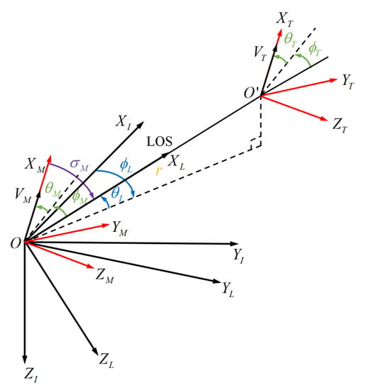
Figure 1.
Munition-target engagement geometry in a 3-D space.
We put forward some assumptions in advance in order to facilitate analysis of the guidance law.
Assumption 1.
The ground coordinate system is inertial, i.e., the influence of the earth’s curvature and rotation can be ignored.
Assumption 2.
The attitude of both loitering munition and target can be ignored, i.e., the body frames coincide with ballistic coordinates of the munition and the target.
Assumption 3.
The velocity of the loitering munition can be regarded as a constant value.
According to the definition of each coordinate system in the terminal guidance process as described above and the corresponding transformation relationship, the following three-dimensional space kinematic relationships of the terminal guidance are defined:
Additionally, since ballistic coordinate frames of the loitering munition and the target are both motion coordinate frames; therefore, the acceleration (, ) of the munition and target in the mutually orthogonal planes can be obtained as:
where , and , represent the acceleration components in and axes of the munition and the target in both ballistic coordinate frames; , and represent the angular velocity vector of the LOS coordinate frame, ballistic coordinate system of both the munition and the target with respect to the LOS coordinate frame, respectively. The specific expressions is defined as follows:
In addition, the path angles of the loitering munition and the target in the inertial coordinate frame , and , can be further expressed as follows:
In order to further obtain the influence of the pitch and yaw acceleration of the loitering munition on the LOS angle. The derivative of Equations (2) and (3) with the Assumption 3, combine with Equations (11)–(14), can be derived as follows:
In this paper, we examine the situations where different impact angle constraints are required to be satisfied in order to maximize the attacking efficiency of the warhead when striking various targets. According to the definition, the impact angle (, ) refers to the deviation of path angles between the loitering munition and the target in the inertial coordinate at the time of collision, which is expressed as follows:
Here the subscripts “F” denote the time of the collision.
Remark 1.
The direction of the munition’ s velocity vector is desired to coincide with that of the LOS angle as much as possible to ensure the minimum miss distance during the terminal attack for the ground fixed target. As for the ground moving target, there needs to be an expected angle between the velocity vector and the direction of LOS. It is known that there exists a transformation relation between the impact angle and the LOS angle. Therefore, TIA constraints in elevation and azimuth plane can be transformed into the expected LOS angle combined with the target motion information [44].
Additionally, a nonlinear relation between the overall leading angle and the two partial leading angles and is defined as follows:
According to the FOV limitation of the photoelectric seeker, the inequality is required to be satisfied. Meanwhile, according to the requirement of the warhead carried by some loitering munitions, the airborne guidance system may be located under the belly. In this case, the partial leading angle is required to meet to avoid view obstruction from the aircraft fuselage.
In conclusion, the design objectives of 3-D terminal guidance law against the maneuvering target can be expressed as follows:
3. Multiple Constraints Based Adaptive BMSC Guidance Law
Based on Equations (15) and (16), the dynamics model of LOS angle can be expressed as follows:
where,
where D denotes the external disturbances of the dynamics system, including motion information of the target and modeling uncertainty (, ). In this paper, the first and second derivatives of the expected LOS angle is set to 0.
Assumption 4.
The modeling uncertainty , is bounded with a constant, i.e., , .
Remark 2.
Due to the difficulty of obtaining exact modeling uncertainties and , according to Assumption 4, a Gaussian distribution with a boundness of ρ is employed in order to represent the unknown modeling uncertainty.
Remark 3.
As it is seen in Equations (20)–(25), the accelerations of the pitch and yaw planes (, ) are highly coupled. However, according to Equations (11) and (12), two partial leading angles can be controlled as state variables, while the overall leading angle is not a state variable in the dynamic’s equations. Consequently, it is requisite to decouple the IACG problem with directly uncontrollable FOV limitation into a tracking control issue based on state constraints in elevation and azimuth directions.
Remark 4.
The analysis shows that the state control process of the LOS angle in the pitch plane is only affected by the acceleration , so can be independently controlled to converge to the desired . Then, after obtaining at every moment, a reasonable is designed to ensure that simultaneously converges to the desired terminal LOS angle in the azimuth direction according to the system dynamics model to obtain real-time changes in the terminal guidance process.
Remark 5.
Given good performance of sliding mode controllers, a novel adaptive back-stepping sliding mode control method is proposed to design the terminal guidance law in this paper. The Lyapunov theory is utilized to validate the stability of guidance control system.
3.1. Guidance Law Design in Pitch Plane
A Lyapunov function based on the error of is defined as follows:
where .
The derivative of is derived:
A virtual control component is defined, where is a positive constant. Then, Equation (27) can be derived:
Furthermore, an error fusion function is defined:
where is also positive constant.
Combined with the equality , can be denoted as follows:
Since the equality always holds, and must converge to zero when converges to zero. Given that, the Lyapunov function is further defined as ,
Considering that the expression of contains target motion information, which is generally impossible to obtain directly for the loitering munition. An adaptive method is proposed to estimate the unknown total uncertainty . Therefore, the Lyapunov function is transformed into in the pitch plane,
where denotes the estimation error of total external disturbances, and is the estimation value of . is a positive constant.
Taking the time derivative of leads to:
where , , are determined by the first row of each matrix in Equations (23)–(25), respectively.
According to the Lyapunov stability theorem, if is negative definite, can asymptotically converge to zero, and , , in finite time.
However, the FOV constraint also has to be focused on in the design of guidance law. Therefore, a FOV angle constraint term is introduced to construct a new Lyapunov function. Aiming at the FOV constraint described in this paper, we design a nonlinear mapping relationship from to a new variable , where the value range of is . The mapping relationship can be specifically expressed as:
Remark 6.
According to the one-to-one mapping relationship between the variables and , the magnitude limitation on can be transformed into the boundedness of . It is clear that if can always be proved bounded, the inequality always holds.
For the equality in Equation (18), if the FOV limitation can be satisfied, we can obtain the following relationship:
Remark 7.
Here, an assumption that holds, where denotes the initial guidance moment. Thus, let , where δ is a small positive constant. Meanwhile, δ satisfies the condition , where
Considering based on the mapping relation between and in the available value range, an error variable is defined as:
where , and is a constant.
The modified Lyapunov function that includes the FOV angle constraint term is expressed as follows:
Taking the derivative of leads to
where
According to the derivation of the Lyapunov function, the guidance law in the elevation direction is designed as follows:
where each parameter is described as follows:
where and are two positive constant values, and we let .
Remark 8.
In the design of terminal guidance law, the external disturbances, including the motion of targets and modeling uncertainties, can be compensated by disturbance estimation with adaptive law about the error variable .
Substituting Equations (42) and (43) into (41) with Equation (11), the derivative of leads to
where , and is defined as:
In order to satisfy the condition that Lyapunov function is monotonically decreasing in the domain, needs to hold. Therefore, according to Equation (44), letting the matrix be definite positive leads to the following:
Here, combined with the guidance dynamics equation, the design of the terminal guidance law in the pitch plane is obtained by using the Lyapunov stability analysis method.
Particularly, the following theorem illustrates the performance of the proposed guidance method.
Theorem 1.
Aiming at the nonlinear guidance control system of the loitering munition, the pitch acceleration is determined according to the design of the guidance command in Equations (42) and (43). In terminal guidance, the LOS angle will converge , the LOS angle rate will converge , and the partial leading angle will always meet the FOV angle constraint condition .
Proof of Theorem 1.
We know the Lyapunov function always holds if the acceleration command in the pitch plane is determined according to Theorem 1, we have , , , and . Therefore, it is concluded as follows:
where , and f denotes the inverse mapping from to .
Moreover, consider the case that the Lyapunov function . It is illustrated that monotonically decreases to have , which means and are bounded. Therefore, it is further proved that is bounded on . According to the one-to-one mapping relation between and , the inequality is finally guaranteed to hold. Hence it proves Theorem 1. □
3.2. Guidance Law Design in Yaw Plane
In this subsection, the guidance command in yaw plane will be reasonably designed to ensure that the LOS angle satisfies based on the pitch plane design. Likewise, an error variable of the LOS angle is defined as , and a virtual control component is defined as , where is a positive constant. A new error fusion variable is then defined as , where is a positive constant.
Combined with the relation , can be further expressed as:
Also, considering the total uncertainty involving the target motion information in the expression of , a new Lyapunov function for azimuth direction is defined as:
where denotes the estimated error of the external disturbances in the yaw plane, denotes the estimation value of , and is a positive constant.
Taking the derivation of leads to the following:
Based on the Lyapunov stability theory, if the condition holds, and converges to zero, we have that , , . In addition, the FOV angle constraint must be considered in the design of yaw guidance command.
According to Equation (18) about the relationship between the overall leading angle and partial leading angles in two directions, a variable with respect to is designed as:
Therefore, in order to satisfy the FOV limitation, construct the following inequality with the change of .
Then, the Equation above can be written as:
Since the inequality Equation (53) holds with the condition , the following relation can be guaranteed:
Therefore, the following inequality always holds:
In view of the above FOV angle constraints, a nonlinear mapping relationship from the variable to a new one is also introduced, where the value range of is , and the mapping relationship can be expressed as:
whereas the following inequality can be obtained by Equation (18)
and the initial partial leading angle also satisfies
Like the situation in pitch plane, a similar error is defined as follows:
where , and is a constant.
Then, the Lyapunov function is updated as:
Differentiating with respect to time yields:
where
According to the definition of , the time derivative can be expressed as:
and can be determined by Equation (12).
Based on the above derivation process of and the elevation guidance law design, the azimuth guidance law can be further designed as follows:
where every term can be determined as follows:
where let . Likewise, and are also two positive constant values.
Substituting Equations (65) and (66) into (61) yields
where , and also let be positive definite expressed as:
therefore,
Finally, the terminal guidance law in yaw plane using Lyapunov stability theory is designed, and the specific expression is given as follows.
Theorem 2.
Proof of Theorem 2.
As we can see, the Lyapunov function always holds if the acceleration command in yaw plane is determined based on Theorem 2, we have that , , , and . Therefore, it is concluded as follows:
where , and g denotes the inverse mapping from to .
Moreover, the Lyapunov function satisfies the stability requirement, indicating that it is monotonically decreasing. Then, is bounded on , and and are also bounded. Thus, we have that is bounded on . According to the one-to-one mapping relation between and , the inequality is satisfied. Furthermore, based on the analysis by Equations (51)–(55), it is verified that FOV angle constraint condition can be guaranteed.
Here, it proves Theorem 2. □
4. Numerical Simulation Analysis
This section implements a series of simulation tests in order to validate the effectiveness of the 3-D adaptive back-stepping sliding mode guidance law based on multiple constraints proposed in this paper. In these simulations, different motion state targets are considered to demonstrate the high adaptability of the presented method. During the guidance process, the loitering munition and target speeds are assumed constant, which are set as m/s and m/s. The initial positions of loitering munitions and targets are selected as () = (0, 0, 700) m, () = (500, 600, 0) m. The corresponding LOS angles are , . In addition, the initial track angles of loitering munitions are set as , and those for moving targets are set as , . Considering that the available accelerations in two directions are limited by the strategy of bank-to-turn limits the available accelerations, the maximum acceleration value is set as m/ in the simulation process. Given the FOV limitation, the values of and are chosen as –10° and 75°. The numerical simulation is terminated by m.
4.1. Simulations for Constant Maneuvering Targets
Firstly, we implement a series of simulations for attacking a constant maneuvering target on the ground. The following three desired cases are considered according to the relationship between terminal impact angles and LOS angles.
- (1)
- Case 1: ;
- (2)
- Case 2: ;
- (3)
- Case 3: .
Consequently, the results of simulations for the constant maneuvering target are shown in Figure 2, Figure 3, Figure 4, Figure 5, Figure 6, Figure 7 and Figure 8 and Table 1. It is adequately illustrated that the proposed terminal guidance law performs extremely well for attacking constant maneuvering targets. Figure 2 and Figure 3 show the changing curve of LOS angles and LOS rates under the three cases in the process of terminal guidance. As we can see, all the desired LOS angles can be satisfied using the proposed method with narrow errors, and the LOS rates converge to the neighborhood of zero. In Figure 4, it is demonstrated that the acceleration commands of two directions start with increasing trends for a while and gradually decrease to zero with the convergence of LOS angles and rates. Figure 5 shows the variations of estimation errors for external disturbances. It is noted that although initial estimation errors are large, they gradually converge to zero neighborhoods as the loitering munition approaches the target gradually. Moreover, it is clearly shown in Figure 6 and Figure 7 that the partial leading angle is greater than 0°, which meets the restriction condition by the seeker. Meanwhile, the maximum FOV angle in the full-trajectory flight of the munition is 73.96°, which also satisfies the FOV angle constraint. In addition, the 3-D trajectories of the loitering munition and the target under the three terminal guidance cases are presented in Figure 8. As shown in Table 1, we list the specific quantitative performance of the proposed guidance method under three cases. In conclusion, the above performance fully verifies that the terminal guidance law algorithm proposed in this paper is effectively suitable for attacks on constant maneuvering targets.
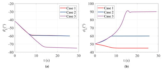
Figure 2.
Variations of LOS angles against constant maneuvering targets: (a) LOS angles in pitch plane; (b) LOS angles in yaw plane.
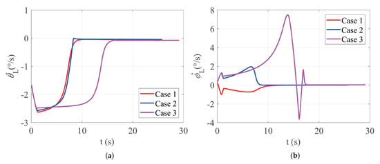
Figure 3.
Variations of LOS rates against constant maneuvering targets: (a) LOS rates in pitch plane; (b) LOS rates in yaw plane.
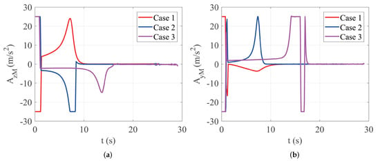
Figure 4.
Variations of acceleration commands against constant maneuvering targets: (a) acceleration commands in pitch plane; (b) acceleration commands in yaw plane.
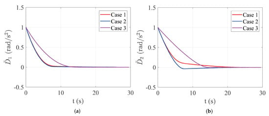
Figure 5.
Variations of estimation errors against constant maneuvering targets: (a) estimation errors in pitch plane; (b) estimation errors in yaw plane.
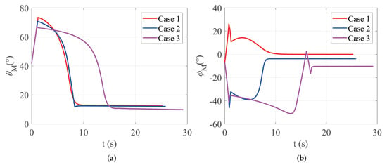
Figure 6.
Variations of partial leading angles against constant maneuvering targets: (a) partial leading angles in pitch plane; (b) partial leading angles in yaw plane.
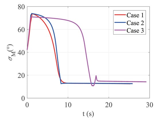
Figure 7.
Variations of overall leading angles against constant maneuvering targets.
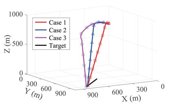
Figure 8.
3-D trajectories of terminal guidance against constant maneuvering targets.

Table 1.
Terminal guidance performance for attacking constant maneuvering targets.
4.2. Simulations for Variable Maneuvering Targets
In this subsection, simulations for attacking a variable maneuvering target on the ground are performed to verify the effectiveness and flexibility of the proposed guidance law algorithm. According to the application background of the investigated loitering munitions in this paper, the variable maneuvering target refers to targets with lateral acceleration variations in the ground plane, and in these simulations, the acceleration of targets is given as follows:
In the simulations, the initial conditions and the limitations are the same as the situations for constant maneuvering targets. Likewise, different desired terminal LOS angles are described as follows:
- (1)
- Case 1:
- (2)
- Case 2:
- (3)
- Case 3:
The numerical simulations for the terminal guidance process of loitering munitions against variable maneuvering targets are carried out under above three cases. The obtained results as shown in Figure 9, Figure 10, Figure 11, Figure 12, Figure 13, Figure 14 and Figure 15 and Table 2. The above results illustrate that the proposed guidance law algorithm performs well for attacking variable maneuvering targets. In Figure 9, terminal LOS angles of the munitions meet the desired requirements, and the error magnitude is very small. Meanwhile, the variations of LOS rates are presented in Figure 10, which shows asymptotic convergence to zero. Remarkably, there exists fluctuation of LOS rates near collision because the violent maneuvering state of targets is more notable near the settling time. Still, they can converge to zero again in a very short period.
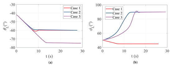
Figure 9.
Variations of LOS angles against variable maneuvering targets: (a) LOS angles in pitch plane; (b) LOS angles in yaw plane.
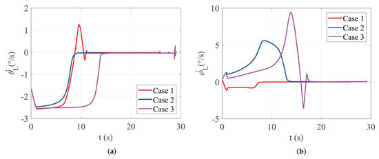
Figure 10.
Variations of LOS rates against variable maneuvering targets: (a) LOS rates in pitch plane; (b) LOS rates in yaw plane.
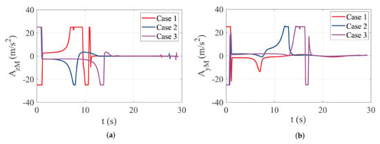
Figure 11.
Variations of acceleration commands against variable maneuvering targets: (a) acceleration commands in pitch plane; (b) acceleration commands in yaw plane.
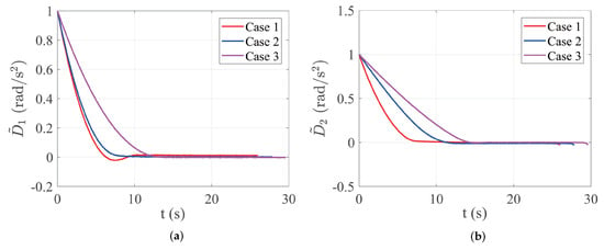
Figure 12.
Variations of estimation errors against variable maneuvering targets: (a) estimation errors in pitch plane; (b) estimation errors in yaw plane.
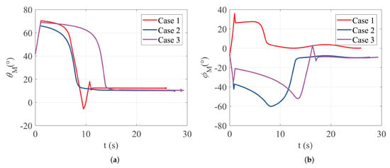
Figure 13.
Variations of partial leading angles against variable maneuvering targets: (a) partial leading angles in pitch plane; (b) partial leading angles in yaw plane.
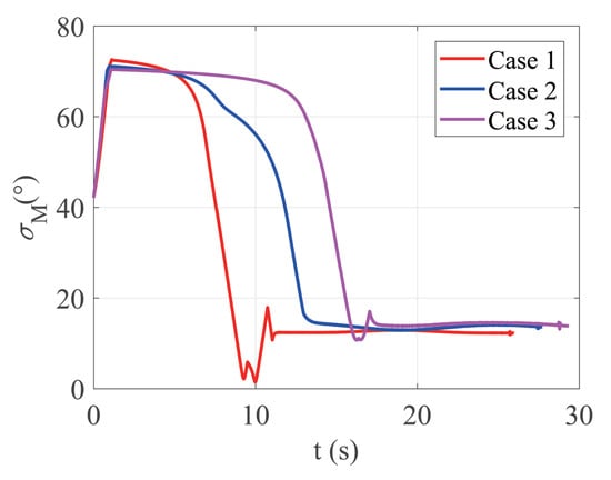
Figure 14.
Variations of overall leading angles against variable maneuvering targets.
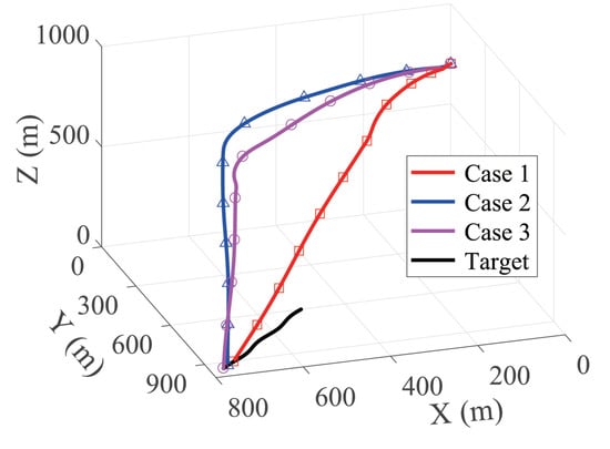
Figure 15.
3-D trajectories of terminal guidance against variable maneuvering targets.

Table 2.
Terminal guidance performance for attacking variable maneuvering targets.
In Figure 11, it is demonstrated that the munition acceleration commands have trends of increasing and then converging. Likewise, several fluctuations of accelerations are created by the variations of LOS rates, but also diminish quickly. It is noted that higher acceleration towards the end of the engagement is generated, especially in case 3, but it quickly converges back to zero neighborhoods. As the range between the loitering munition and target decreases gradually, a small maneuvering change could cause a violent variation away from desired LOS angles, especially at the end of the ballistic trajectory. Therefore, a higher acceleration command is needed to correct fluctuations of LOS angles. On the contrary, if the guidance law generates still small acceleration in the situation above, the terminal LOS angles constraints may not be satisfied, which thoroughly validates the robustness of the proposed guidance method.
In Figure 12, estimation errors for overall disturbances are shown with a gradual decreasing trend, demonstrating the ability to deal with target maneuvering and external interference. While considering the FOV constraints of the aircraft during the terminal guidance process, as shown in Figure 13 and Figure 14, it is clear that the partial leading angles , and the overall leading angles both meet their respective constraints, where the minimum is −5.43° and the maximum is 72.61°. In addition, Figure 15 presents the 3-D trajectories of loitering munitions and variable maneuvering targets under three cases. In summary, the above performance adequately verifies the effectiveness and feasibility of the terminal guidance law algorithm proposed in this paper when attacking variable maneuvering targets.
5. Conclusions
In this paper, a novel terminal guidance design method against maneuvering targets is presented while considering multiple constraints, including TIA (LOS) constraints and FOV limitations, for the purpose that loitering munitions can capture maneuvering targets and effectively improve damage efficiency. Given various terminal restrictions, a 3-D guidance model with a high coupling relationship disturbed by complex motion of maneuvering targets is investigated, which has highly practical application significance. The novel guidance law is developed by integrating TIA (LOS) constraints and FOV limitation components into a 3-D adaptive back-stepping sliding mode control algorithm using the Lyapunov stability analysis method to adapt to different maneuvering targets. The motion information of targets is regarded as external disturbances, which are estimated and compensated by the design of adaptive laws. Moreover, the FOV angle represented by the overall leading angle is decoupled into two partial leading angles in pitch and yaw directions based on a specific transformation method, which can guarantee the FOV limitation. Finally, the effectiveness and universality of the proposed guidance law algorithm are verified by numerical simulation experiments against different maneuvering targets under various terminal LOS angle constraints.
In our following research, the velocity and attitude variations of loitering munitions will be considered during the terminal guidance process.
Author Contributions
Conceptualization, Q.S. and H.W.; methodology, Q.S., H.W. and H.C.; software, Q.S. and H.C.; validation, Q.S. and H.C.; formal analysis, Q.S.; investigation, H.C.; resources, H.C.; data curation, Q.S.; writing—original draft preparation, Q.S.; writing—review and editing, Q.S., H.W. and H.C.; visualization, Q.S.; supervision, H.C.; project administration, H.W.; funding acquisition, H.W. All authors have read and agreed to the published version of the manuscript.
Funding
This research received no external funding.
Institutional Review Board Statement
Not applicable.
Informed Consent Statement
Not applicable.
Data Availability Statement
Not applicable.
Acknowledgments
Not applicable.
Conflicts of Interest
The authors report no conflict of interest. All authors are responsible for the contents in and the writing of this article.
References
- Kim, B.S.; Lee, J.G.; Han, H.S. Biased PNG law for impact with angular constraint. IEEE Trans. Aerosp. Electron. Syst. 1998, 34, 277–288. [Google Scholar]
- Lee, C.H.; Kim, T.H.; Tahk, M.J. Interception angle control guidance using proportional navigation with error feedback. J. Guid. Control Dyn. 2013, 36, 1556–1561. [Google Scholar] [CrossRef]
- Pang, W.; Xie, X.; Sun, T. Improved bias proportional navigation with multiple constraints for guide ammunition. J. Syst. Eng. Electron. 2017, 28, 1193–1202. [Google Scholar]
- Budiyono, A.; Rachman, H. Proportional guidance and CDM control synthesis for a short-range homing surface-to-air missile. J. Aerosp. Eng. 2012, 25, 168–177. [Google Scholar] [CrossRef]
- Ratnoo, A.; Ghose, D. Impact angle constrained interception of stationary targets. J. Guid. Control Dyn. 2008, 31, 1817–1822. [Google Scholar] [CrossRef]
- Erer, K.S.; Merttopcuoglu, O. Indirect impact-angle-control against stationary targets using biased pure proportional navigation. J. Guid. Control Dyn. 2012, 35, 700–704. [Google Scholar] [CrossRef]
- Bryson, A.E. Applied Optimal Control; Blaisdell: Waltham, MA, USA, 1969. [Google Scholar]
- Yu, W.; Chen, W.; Yang, L.; Liu, X.; Zhou, H. Optimal terminal guidance for exoatmospheric interception. Chin. J. Aeronaut. 2016, 29, 1052–1064. [Google Scholar] [CrossRef][Green Version]
- Park, B.G.; Kim, T.H.; Tahk, M.J. Range-to-go weighted optimal guidance with impact angle constraint and seeker’s look angle limits. IEEE Trans. Aerosp. Electron. Syst. 2016, 52, 1241–1256. [Google Scholar] [CrossRef]
- Banerjee, A.; Nabi, M.; Raghunathan, T. Time-energy optimal guidance strategy for realistic interceptor using pseudospectral method. Trans. Inst. Meas. Control 2020, 42, 2361–2371. [Google Scholar] [CrossRef]
- Park, B.G.; Kim, T.H.; Tahk, M.J. Optimal impact angle control guidance law considering the seeker’s field-of-view limits. Proc. Inst. Mech. Eng. Part G J. Aerosp. Eng. 2013, 227, 1347–1364. [Google Scholar] [CrossRef]
- Li, Z.; Xia, Y.; Su, C.Y.; Deng, J.; Fu, J.; He, W. Missile guidance law based on robust model predictive control using neural-network optimization. IEEE Trans. Neural Netw. Learn. Syst. 2015, 26, 1803–1809. [Google Scholar] [CrossRef]
- Lee, S.; Lee, H.; Kim, Y.; Kim, J.; Choi, W. GPU-accelerated PD-IPM for real-time model predictive control in integrated missile guidance and control systems. Sensors. 2022, 22, 4512. [Google Scholar] [CrossRef] [PubMed]
- Park, J.; Kim, Y.; Kim, J.H. Integrated guidance and control using model predictive control with flight path angle prediction against pull-up maneuvering target. Sensors. 2020, 20, 3143. [Google Scholar] [CrossRef]
- Bhattacharjee, D.; Chakravarthy, A.; Subbarao, K. Nonlinear model predictive control and collision-cone-based missile guidance algorithm. J. Guid. Control Dyn. 2021, 44, 1481–1497. [Google Scholar] [CrossRef]
- Bachtiar, V.; Manzie, C.; Kerrigan, E.C. Nonlinear model-predictive integrated missile control and its multiobjective tuning. J. Guid. Control Dyn. 2017, 40, 2958–2967. [Google Scholar] [CrossRef]
- Padhi, R.; Kothari, M. Model predictive static programming: A computationally efficient technique for suboptimal control design. Interna. J. Innova. Comput. Informa. Control. 2009, 5, 399–411. [Google Scholar]
- Maity, A.; Oza, H.B.; Padhi, R. Generalized model predictive static programming and angle-constrained guidance of air-to-ground missiles. J. Guid. Control Dyn. 2014, 37, 1897–1913. [Google Scholar] [CrossRef]
- Zhou, C.; Yan, X.; Tang, S. Generalized quasi-spectral model predictive static programming method using Gaussian quadrature collocation. Aerosp. Sci. Technol. 2020, 106, 106134. [Google Scholar] [CrossRef]
- Isaacs, R. Differential Games; John Wiley & Sons: New York, NY, USA, 1965. [Google Scholar]
- Tang, S.T. Performance comparison of differential game and improvement proportional navigation guidance laws. J. Astronaut. 2002, 23, 38–42. [Google Scholar]
- Turetsky, V.; Weiss, M.; Shima, T. A combined linear–quadratic/bounded control differential game guidance law. IEEE Trans. Aerosp. Electron. Syst. 2021, 57, 3452–3462. [Google Scholar] [CrossRef]
- Duan, D.; Liu, C.; Sun, J. Adaptive periodic event-triggered control for missile-target interception system with finite-horizon convergence. Trans. Inst. Meas. Control 2020, 42, 1808–1822. [Google Scholar] [CrossRef]
- Bardhan, R.; Ghose, D. Nonlinear differential games-based impact-angle-constrained guidance law. J. Guid. Control Dyn. 2015, 38, 384–402. [Google Scholar] [CrossRef]
- Zames, G. Feedback and optimal sensitivity: Model reference transformations, multiplicative seminorms, and approximate inverses. IEEE Trans. Automa. Control 1981, 26, 301–320. [Google Scholar] [CrossRef]
- Yang, C.D.; Chen, H.Y. Nonlinear H∞ robust guidance law for homing missiles. J. Guid. Control Dyn. 1998, 21, 882–890. [Google Scholar] [CrossRef]
- Chwa, D. Robust nonlinear disturbance observer based adaptive guidance law against uncertainties in missile dynamics and target maneuver. IEEE Trans. Aerosp. Electron. Syst. 2018, 54, 1739–1749. [Google Scholar] [CrossRef]
- Brierley, S.D.; Longchamp, R. Application of sliding-mode control to air-air interception problem. IEEE Trans. Aerosp. Electron. Syst. 1990, 26, 306–325. [Google Scholar] [CrossRef]
- Hou, M.; Liang, X.; Duan, G. Adaptive block dynamic surface control for integrated missile guidance and autopilot. Chin. J. Aeronaut. 2013, 26, 741–750. [Google Scholar] [CrossRef]
- Zhao, F.J.; You, H. New three-dimensional second-order sliding mode guidance law with impact-angle constraints. Aeronaut. J. 2019, 124, 1–17. [Google Scholar] [CrossRef]
- Ming, C.; Wang, X.; Sun, R. A novel non-singular terminal sliding mode control-based integrated missile guidance and control with impact angle constraint. Aerosp. Sci. Technol. 2019, 94, 105368. [Google Scholar] [CrossRef]
- Wen, Q.; Xia, Q.; Su, W. A parameter design strategy for seeker’s field-of-view constraint in impact angle guidance. Proc. Inst. Mech. Eng. Part G J. Aerosp. Eng. 2015, 229, 2389–2396. [Google Scholar] [CrossRef]
- He, S.; Lin, D. A robust impact angle constraint guidance law with seeker’s field-of-view limit. Trans. Inst. Meas. Control 2015, 37, 317–328. [Google Scholar] [CrossRef]
- Ai, X.; Wang, L.; Yu, J.; Shen, Y. Field-of-view constrained two-stage guidance law design for three-dimensional salvo attack of multiple missiles via an optimal control approach. Aerosp. Sci. Technol. 2019, 85, 334–346. [Google Scholar] [CrossRef]
- Kim, H.G.; Lee, J.Y.; Kim, H.J.; Kwon, H.H.; Park, J.S. Look-angle-shaping guidance law for impact angle and time control with field-of-view constraint. IEEE Trans. Aerosp. Electron. Syst. 2019, 56, 1602–1612. [Google Scholar] [CrossRef]
- Ma, S.; Wang, X.; Wang, Z.; Chen, Q. Three-dimensional impact time control guidance considering field-of-view constraint and velocity variation. Aerosp. 2022, 9, 202. [Google Scholar] [CrossRef]
- Lee, S.; Kim, Y. Capturability of impact-angle control composite guidance law considering field-of-view limit. IEEE Trans. Aerosp. Electron. Syst. 2020, 56, 1077–1093. [Google Scholar] [CrossRef]
- Zhou, S.; Hu, C.; Wu, P.; Zhang, S. Impact angle control guidance law considering the seeker’s field-of-view constraint applied to variable speed missiles. IEEE Access 2020, 8, 100608–100619. [Google Scholar] [CrossRef]
- Kim, H.G.; Kim, H.J. Field-of-view constrained guidance law for a maneuvering target with impact angle control. IEEE Trans. Aerosp. Electron. Syst. 2020, 56, 4974–4983. [Google Scholar] [CrossRef]
- Ma, S.; Wang, X.; Wang, Z. Field-of-view constrained impact time control guidance via time-varying sliding mode control. Aerosp. 2021, 8, 251. [Google Scholar] [CrossRef]
- He, S.; Lee, C.H.; Shin, H.S.; Tsourdos, A. Optimal three-dimensional impact time guidance with seeker’s field-of-view constraint. Chin. J. Aeronaut. 2021, 34, 240–251. [Google Scholar] [CrossRef]
- Saleem, A.; Lisy, E.R. Three dimensional nonlinear guidance law for exact impact time control. IEEE Access 2022, 10, 67350–67362. [Google Scholar] [CrossRef]
- Kumar, P.; Dwivedi, P.N.; Bhattacharyya, A.; Padhi, R. Terminal-lead-angle-constrained generalized explicit guidance. IEEE Trans. Aerosp. Electron. Syst. 2017, 53, 1250–1260. [Google Scholar] [CrossRef]
- Hu, Q.L.; Han, T.; Xin, M. Three-Dimensional Guidance for Various Target Motions With Terminal Angle Constraints Using Twisting Control. IEEE Trans. Indust. Electron. 2020, 67, 1242–1253. [Google Scholar] [CrossRef]
Publisher’s Note: MDPI stays neutral with regard to jurisdictional claims in published maps and institutional affiliations. |
© 2022 by the authors. Licensee MDPI, Basel, Switzerland. This article is an open access article distributed under the terms and conditions of the Creative Commons Attribution (CC BY) license (https://creativecommons.org/licenses/by/4.0/).