Abstract
Whirl flutter of a tiltrotor aircraft is a complex aeroelastic phenomenon and it can result in catastrophic consequences. The deflection of an aileron mounted on a wing has the potential to solve this fatal problem. Whirl flutter suppression using an actively controlled aileron is studied in this study. Firstly, a semi-span aeroelastic model is established for the whirl flutter problem using the Hamilton principle. This model is composed of three parts: a rigid rotor, a rigid nacelle and a flexible wing, and the effect of the aileron deflection on the aeroelastic responses is also taken into consideration through a quasi-steady aerodynamic model. In addition, the accuracy of this aeroelastic model is validated with the results of two different wind-tunnel tests. Then, an LQR controller is developed to control the dynamic deflection of the aileron, and a full-dimensional state observer is built to estimate the state of the time-invariant system of a tiltrotor aircraft. Finally, simulations are carried out using the aeroelastic model and the LQR controller at different flight conditions to study the influence of the aileron deflection on whirl flutter. The simulation results demonstrate that the flutter boundary speed can be improved by 18.1% with the active deflection of the aileron, compared with the uncontrolled condition.
1. Introduction
Tiltrotor aircraft combine the advantages of helicopters and fixed-wing propeller-driven aircraft with hovering and high-speed forward flight. This type of aircraft, however, suffers from dynamic instability problems resulting from aeroelastic coupling between the rotor and flexible wing. In high-speed flight conditions, the in-plane aerodynamics resulting from blade flap movement couple with the flapping and torsional deformation of the flexible wing. This coupling causes the instability of whirl flutter and limit the high-speed advantage of tiltrotor aircraft.
In general, there are two different ways to suppress the whirl flutter of tiltrotor aircraft, namely active control and passive control. Typical passive control methods, such as blade geometry optimization and aeroelastic tailoring [1,2,3,4,5,6], enable favorable coupling between the rotor and the flexible wing to improve the stability boundary of whirl flutter. In recent years, new concepts of passive control, including extensions and winglets, have received increasing attention [7,8,9], and their principle is to generate a restoring force which is opposite to the twist motion of the flexible wing, using these additional aerodynamic surfaces, thus suppressing whirl flutter.
Active control has shown its peculiar advantages in vibration alleviation and aeroelastic stability augmentation, and its application in the whirl flutter suppression of tiltrotor aircraft dates back to the 1970s. Depending on the technical implementation, active control methods for whirl flutter suppression can be generally divided into two categories, including active control through the swashplate of the rotor and active control through ailerons mounted on a flexible wing. In 1973, Boeing added feedback control to the Boeing Model 222 rotor [10], and the modal damping of the wing vertical bending mode, which was critical for the whirl flutter phenomenon, was increased through the active control of the collective and cyclic pitch angles of the rotors. In 1986, Nasu et al. at the NASA Ames Research Center used APC (Active Pitch Control) to control the longitudinal cyclic control of the rotor and selected the chord bending velocity as the feedback signal [11]. It was shown that this method was capable of improving the boundary velocity of whirl flutter. In 2004, Mueller et al. of Eurocopter conducted an aeroelastic study by combining multibody dynamics and a GPC (Generalized Predictive Control) algorithm, in which the wing bending deformation was used as the feedback signal to control the input of the swashplate, and the simulation results demonstrated that the GPC control was able to extend the whirl flutter boundary by 21% [12]. In 2017, Matthew et al. carried out a simulation study of the influence of active wing tips on whirl flutter stability [13]. The deflection of the wing tips, which was controlled by a PID controller, was capable of increasing the boundary velocity from 160 kts to over 200 kts, demonstrating that a movable aerodynamic surface had the potential to improve the boundary velocity of whirl flutter. Paik et al. examined the effectiveness of two different methods of active stability augmentation, including wing-flaperon and swashplate actuation, and feedback control based on the wing states was used instead of full-state control for simplicity [14]. A new wind-tunnel test model named Tiltrotor Aeroelastic Stability Testbed (TRAST) was developed by the US Army and NASA, and an active stability augmentation test was conducted with this testbed [15,16]. Ivanco et al. performed a simulation of active stability augmentation and vibration reduction on a tiltrotor model; in this study, an aeroelastic model was established for the TRAST model using the Rotorcraft Comprehensive Analysis System (RCAS), and a GPC algorithm was used for the blade pitch [17].
The aforementioned studies have proven the effectiveness of active stability augmentation methods. In order to further improve the performance of active whirl flutter suppression, an active control method based on an LQR algorithm and full-order state observer was built and tested through simulation. A comprehensive aeroelastic model composed of a rigid rotor, a flexible wing and a rigid nacelle was established. Aerodynamics generated by the aileron were calculated using a quasi-steady model. The experiment results of two different wind-tunnel tests were used to validate the accuracy of this aeroelastic model. An active controller was designed based on an LQR (Linear Quadratic Regulator) algorithm to control the deflection movement of the aileron. A full-order state observer was built to obtain the unmeasurable variables of the flexible wing, which were used as the feedback signals in the active control. The simulations were conducted at different flight conditions to suppress whirl flutter using the established aeroelastic model combined with the LQR controller. Based on the simulation results, a semi-span model equipped with an actively controlled aileron will be designed and tested in a wind tunnel for further validation of the active stability augmentation method.
2. Aeroelastic Model
2.1. Definition of Coordinate Systems
According to numerical research results, the symmetric modal coupling between the rotor and flexible wing of a tiltrotor aircraft is more prone to whirl flutter than the antisymmetric modal coupling [18], making a semi-span model sufficient for whirl flutter simulation. In addition, this type of model can dramatically reduce the computational cost. Therefore, a semi-span aeroelastic model was built in this study.
A series of coordinate systems were established to describe the motion and deformation of the semi-span model. The flexible wing and the coordinate systems defined on the rotor are shown in Figure 1.
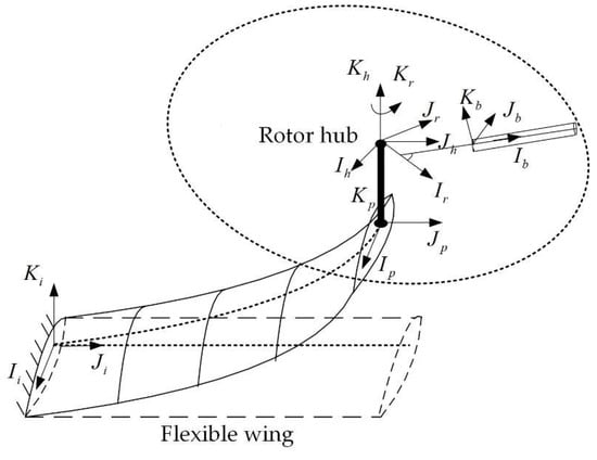
Figure 1.
Flexible wing and coordinate systems defined on the rotor.
As shown in Figure 1, the origin of the inertial coordinate system is defined at the root of the wing elastic axis. The origin of the undeformed coordinate system is located at the wing elastic axis. Three twist angles are generated between the deformed coordinate system and the undeformed coordinate system of the flexible wing due to its elastic deformation. The nacelle coordinate system is used to describe the movement of the rigid nacelle, with the origin defined on the tilt hinge, and are the biases of the origin with respect to the wing elastic axis. is the tilt angle of the nacelle, with the angle corresponding to the helicopter mode defined as 0°. is the rotor hub coordinate system, with its origin defined at the center of the hub, and are the biases of the origin with respect to the tilt hinge. The rotor rotating coordinate system is generated by rotating the rotor hub coordinate system an azimuth of . The blade rigid flap coordinate system is established by rotating the an angle of around the axis, with being the flap angle of the blade, and being the precone angle of the rotor hub. The blade pitch coordinate system , which is used to describe the rigid flapping and pitching motion of the rotor blades, is attached to the pitching hinge.
2.2. Hamilton Principle
The aeroelastic dynamic equations of the semi-span model are derived using the Hamilton principle [19,20,21,22] as expressed in Equation (1):
In Equation (1), is the virtual elastic potential energy of the model, including the elastic wing and the rotor hub, given by:
is the virtual kinetic energy, which combines the virtual kinetic energy of the elastic wing, the nacelle and the rotor blades, and is calculated by:
is the virtual work of the aerodynamics. In this study, the aerodynamics of the wing and the rotor blades are taken into consideration. is estimated as:
2.3. Flexible Wing Model
The flexible wing is one of the most fundamental parts of the semi-span model, and its elastic deformation is taken into consideration, while the movement of the fuselage is ignored. Therefore, the wing can be modeled as a cantilever beam as shown in Figure 2.
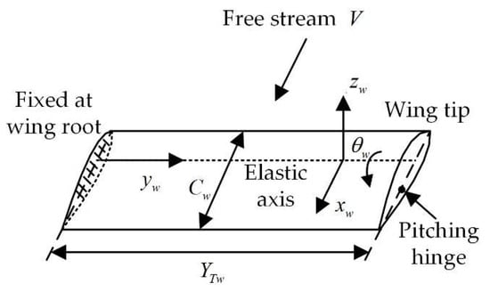
Figure 2.
Schematic of the flexible wing.
The motion modes of the flexible wing include the flap bending mode , chordwise bending mode and torsional mode , and mode shape functions are used to describe the elastic deformation of the wing of these three modes. Since the whirl flutter boundary of the tiltrotor aircraft is primarily determined by the lower modes of the flexible wing, only the lowest order of the motion modes is retained, so that the elastic deformation of the wing can be described as:
where , and are the flap bending displacement, the chordwise bending displacement and the twist angle of the wing, respectively.
After defining the deformation of the flexible wing, its elastic potential energy can be calculated by:
Then, the stiffness matrix related to the elastic potential energy can be determined using:
The kinetic energy of the wing is given as:
The virtual kinetic energy of the wing can be described as generalized forces as:
The mass matrix related to the kinetic energy of the wing can be evaluated by:
The work of the aerodynamics acting on the wing is expressed as:
In Equation (13), is the non-dimensioned bias of the aerodynamic center with respect to the elastic axis. The virtual work of the wing related to the aerodynamics can be described as generalized forces as:
The damping matrix and stiffness matrix related to the aerodynamic work are as follows:
The structural damping of the flexible wing can be expressed as:
where is the modal damping, is the modal mass, is the modal stiffness and is the modal damping ratio.
2.4. Nacelle Model
The nacelle is mainly composed of several large components, such as the engine and rotor shaft. The elastic deformation of these components is not strongly related to whirl flutter; hence, the nacelle can be described by a rigid model. Any point on the nacelle can be expressed as:
where is the bias of the nacelle connection point with respect to the elastic axis of the wing, is the coordinate of any point located in the nacelle coordinate system and is the displacement vector of the wing tip. The velocity of any point related to the nacelle can be calculated by:
Then, yields the virtual kinetic energy of the nacelle:
The degrees of freedom (dof) of the nacelle are identical to those of the wing, and . Hence, the linearized mass matrix of the nacelle can be expressed as:
2.5. Rotor Model
In this aeroelastic model, the flap bending stiffness of the rotor hub with a universal joint is taken into consideration, while each rotor blade is treated as a rigid body. Then, the virtual elastic potential energy of the ith rotor blade resulting from the flap motion can be expressed as:
where is the flap bending stiffness of the rotor hub. The flapping angle of the ith rotor blade , which is related to the rigid flapping dof of the rotor hub, can be expressed in terms of the flapping dof of the rotor hub and the azimuth of the ith rotor blade:
Adding the virtual elastic potential energy of each blade together yields the virtual elastic potential energy of the rotor:
The dof of the rigid rotor blade, which combines the convected motion resulting from the wing elastic deformation and the blade’s rotating dof , is expressed as . The position vector of any point in the blade coordinate system can be expressed in the inertial coordinate system as:
The velocity of this point is calculated by:
Then, the virtual kinetic energy of each blade is given by:
Using the zero-time end condition and exchanging the order of integration, we can obtain:
The virtual kinetic energy of each blade can be described as generalized forces as:
The linearized mass matrix of the rotating blade can be represented as:
Then, the stiffness matrix and damping matrix related to the blade virtual kinetic energy are given by:
The transformation from the rotating frame to the non-rotating frame is expressed by:
The sectional aerodynamic loads acting on the rotor blade are given by:
Decomposing these loads into components perpendicular and parallel to the rotor disk, we will obtain:
The sectional aerodynamic loads of the rotor blade are denoted as:
They can be expressed in the inertial coordinate system as:
Then, the virtual aerodynamic work of each blade can be calculated by:
The virtual work of each blade related to the aerodynamics can be described as generalized forces as:
Finally, the stiffness matrix and damping matrix related to the aerodynamic loads can be determined as:
2.6. Aerodynamics of the Aileron
According to quasi-steady aerodynamic theory [23,24], the additional aerodynamic loads generated by the aileron, including lift and moment , can be calculated using the pitch angle , angular velocity and angular acceleration of the aileron as follows:
These loads are denoted as:
In this study, the deflection motion of the aileron is selected as the control input. Therefore, the linearized governing equation of the semi-span model is given in the following form:
where . , and represent the flap bending mode, chordwise bending mode and twisting mode of the flexible wing, respectively. and are the flapping angles of the rotor hub described in the non-rotating coordinate system of the rotor hub.
2.7. Model Validation I
Firstly, the wind-tunnel test, which was conducted by Bell Helicopter with a full-scaled semi-span tiltrotor model [25], was chosen to validate the accuracy of the established model in this study. This test was performed at the 40-by-80-foot wind tunnel at the Ames Research Center, and the fundamental parameters of this test model are listed in Table 1.

Table 1.
Fundamental parameters of the Bell test model [25].
The modal damping and the modal frequencies of this semi-span model at different flight speeds were calculated by the aeroelastic model built in this study. As shown in Figure 3, the calculated values are in good agreement with the experiment results given in reference, indicating that the established aerodynamic model is of high accuracy.
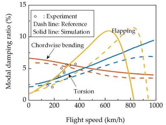
Figure 3.
Variation of wing modal damping ratio with cruise speed.
2.8. Model Validation II
In order to study the aeroelastic characteristics of the tiltrotor aircraft and to validate the accuracy of the numerical methods, we performed a wind-tunnel test with a scaled semi-span model, as shown in Figure 4. The basic parameters of this model are listed in Table 2, and more detail about the wind-tunnel test can be found in [26].
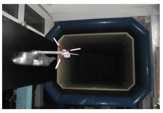
Figure 4.
Wind-tunnel test with a scaled semi-span model.
Table 2.
Fundamental parameters of the scaled semi-span model.
In the wind-tunnel tests, the nacelle vibrations were measured at different wind speeds using accelerometers, which were fixed on the nacelle. The vibration responses at wind speeds of 15 m/s and 20.5 m/s are shown in Figure 5. It can be seen that, at a wind speed of 20.5 m/s, the nacelle vibration increased dramatically, and whirl flutter phenomenon appeared.
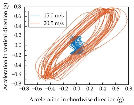
Figure 5.
Nacelle vibrations at different wind speeds.
Numerical simulations were carried out with the established aeroelastic model, in which a transient response analysis method was employed. The torsion responses at about 20 m/s are demonstrated in Figure 6. The wing torsion response converges slowly at a wind speed of 20 m/s; however, if the wind speed increases to 21 m/s, the response cannot converge, illustrating that the whirl flutter boundary of this semi-span model is around 21 m/s, which is in good agreement with the test results.
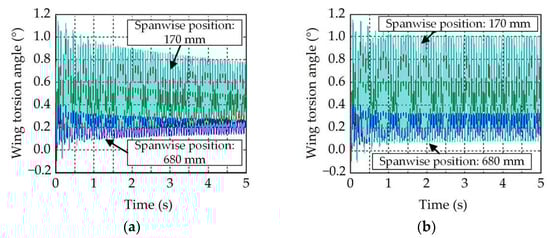
Figure 6.
Wing torsion responses at different wind speeds: (a) 20 m/s; (b) 21 m/s.
3. Active Controller and State Observer
3.1. Active Controller Based on LQR Algorithm
For the time-invariant system of the semi-span tiltrotor model, its state equation and output equation can be expressed as:
where , .
The objective function is defined as:
In Equation (47), and are the weight matrices. In performing the Laplace transformation on Equation (46), the following is obtained:
Then:
Applying the inverse Laplace transformation to Equation (49) yields:
Given that the feedback control signal satisfies the following relationship:
Here, the state feedback control is defined, as represented by in Figure 7.
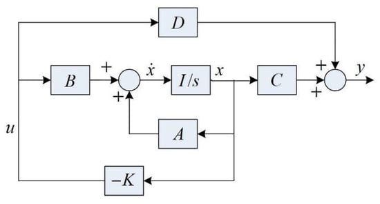
Figure 7.
Diagram of state feedback control.
Substituting Equation (51) into Equation (46) yields:
where
With the state feedback control, the natural vibration characteristics of the semi-span model are determined by matrix . The solution of Equation (52) has the following form:
Then, the objective function defined by Equation (47) becomes:
According to the optimal control theory, the optimal controller can be obtained as:
should satisfy the following Riccati equation:
According to Equation (51), the controller output is determined by state variable ; however, it is not practically measurable. Therefore, a state observer is needed which will be described in the following section.
3.2. State Observer
Since it is convenient to measure the acceleration responses of the semi-span model in wind-tunnel tests, the accelerations are selected in this study to reconstruct the state variable using a state observer. The dynamic equations of a full-order state observer can be expressed as:
Then,
In Equation (59), is defined as the system matrix of the state observation, and is an n-by-q matrix.
The estimation error of the state observer can be given by combining Equation (46) and Equation (59):
The convergence of the estimation error relies on the configuration of matrix . Provided that the real parts of its eigenvalues are negative, the estimation error will converge rapidly, and the convergence rate depends on the pole configuration of the observer. The observer designed in this study is shown in Figure 8.
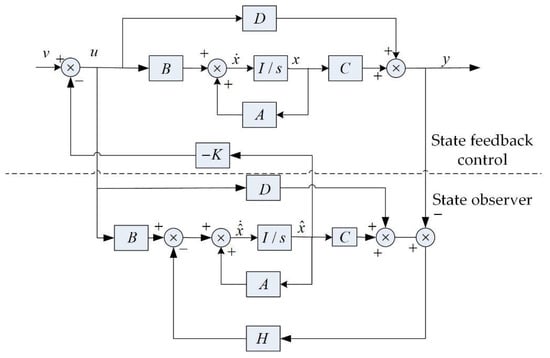
Figure 8.
Diagram of state observer.
4. Simulation Results
4.1. Model Configuration
A simulation model was established by adding an actively controlled aileron to the Bell semi-span model as shown in Figure 9. The distance between the pitching axis of the aileron and the aerodynamic center of the airfoil is , while the distance between the wing root and the inner end of the aileron is . The maximum deflection amplitude of the aileron is limited to ±6°. Other characteristics of the simulation model, such as the stiffness and inertia configuration, are identical to the Bell model.
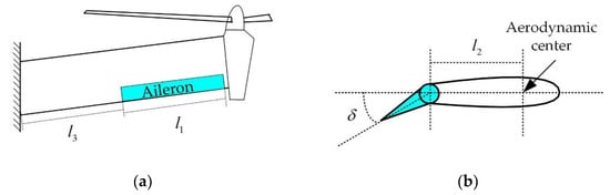
Figure 9.
Schematic of the simulation model: (a) Aileron mounted on the wing; (b) Cross section of wing with aileron.
4.2. Whirl Flutter Suppression
A root locus was applied to evaluate the stability of the semi-span model. As shown in Figure 10a, if the LQR controller is turned off, the root locus, which corresponds to the wing flapping mode, crosses the imaginary axis and moves into the right half of the s-plane at a forward flight speed of 828 km/h, meaning whirl flutter occurs.
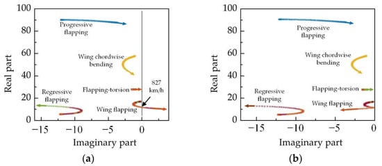
Figure 10.
Root locus of the semi-span model: (a) with controller off; (b) with controller on.
Figure 10b demonstrates the root locus of the semi-span model with the LQR controller turned on. In this condition, the root locus remains in the left half of the s-plane, illustrating that the system is stable and the actively controlled aileron combined with the LQR controller is effective in improving the whirl flutter stability of the tiltrotor aircraft.
Transient response analyses were performed at forward flight speeds of 920 km/h, 970 km/h and 990 km/h. At the 10th second, an acceleration disturbance was applied at the end of the wing to stimulate its whirl flutter, and the deflection angle of the aileron is shown in Figure 11. It could be seen that the aileron responded rapidly to suppress whirl flutter, demonstrating the effectiveness of the aileron as well as the established active controller.
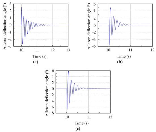
Figure 11.
Deflection of aileron at different flight speeds: (a) 920 km/h; (b) 970 km/h; (c) 990 km/h.
5. Conclusions
In this study, a semi-span aeroelastic model was established for a tiltrotor aircraft to evaluate the influence of an aileron on whirl flutter phenomenon. In this model, the elastic deformation of the wing and rotor hub was taken into consideration, while the rotor blades and nacelle were treated as a rigid body. An active controller combined with a full-order state observer was built to control the deflection of the aileron. Numerical simulations were carried out at different forward flight speeds. The principal conclusions are as follows:
Firstly, the established aeroelastic model is capable of predicting the whirl flutter boundary of a tiltrotor aircraft. Secondly, a wing-mounted aileron, which was controlled by a controller based on an LQR algorithm and full-order state observer, is effective in increasing the whirl flutter stability. For the simulation model in this study, its boundary speed of whirl flutter was increased from 828 km/h to above 978 km/h.
Future works will focus on experimental research on whirl flutter suppression using an actively controlled aileron. A scaled model equipped with an aileron driven by piezoelectric actuators was proposed and wind-tunnel tests were scheduled in the following years.
Author Contributions
Methodology, L.D.; software, L.D.; data processing, Q.L.; validation, L.D.; writing—original draft preparation, L.D.; writing—review and editing, L.D.; supervision, L.D.; project administration, L.D.; funding acquisition, L.D. All authors have read and agreed to the published version of the manuscript.
Funding
This research was funded by the National Natural Science Foundation of China (Grant No. 11402110) and Priority Academic Program Development of Jiangsu Higher Education (PAPD).
Conflicts of Interest
The authors declare no conflict of interest.
References
- Park, J.S.; Jun, S.N.; Lee, M.K.; Kim, J.M. Design optimization framework for tiltrotor composite wings considering whirl flutter stability. Compos. Part B-Eng. 2010, 41, 257–267. [Google Scholar] [CrossRef]
- Kim, T.S.; Lim, J.H.; Shin, A.J.; Kim, D.H. Structural design optimization of a tiltrotor aircraft composite wing to enhance whirl flutter stability. Compos. Struct. 2013, 95, 283–294. [Google Scholar] [CrossRef]
- Stodieck, O.; Cooper, J.; Weaver, P.M.; Kealy, P. Optimization of tow-steered composite wing laminates for aeroelastic tailoring. AIAA J. 2015, 53, 2203–2215. [Google Scholar] [CrossRef]
- Park, J.S.; Kim, S.H.; Jung, S.N.; Lee, M.K. Design and analysis of variable-twist tiltrotor blades using shape memory alloy hybrid composites. Smart Mater. Struct. 2010, 20, 015001. [Google Scholar] [CrossRef]
- Lake, R.C.; Nixon, M.W.; Wilbur, M.L.; Singleton, J.D.; Mirick, P.H. Demonstration of an elastically coupled twist control concept for tilt rotor blade application. AIAA J. 2015, 32, 1549–1551. [Google Scholar] [CrossRef]
- Belardo, M.; Marano, A.D.; Beretta, J.; Diodati, G.; Graziano, M.; Capasso, M.; Ariola, P.; Orlando, S.; Di Caprio, F.; Paletta, N.; et al. Wing structure of the next-generation civil tiltrotor: From concept to preliminary design. Aerospace 2021, 8, 102. [Google Scholar] [CrossRef]
- Sandilya, K. Optimization of Composite Tiltrotor Wings with Extensions and Winglets. Ph.D. Thesis, Pennsylvania State University, State College, PA, USA, 2016. [Google Scholar]
- Cole, J.; Maughmer, M.; Bramesfeld, G. Aerodynamic Design Considerations for Tiltrotor Wing Extensions and Winglets. In Proceedings of the 51st AIAA Aerospace Sciences Meeting including the New Horizons Forum and Aerospace Exposition, Grapevine, TX, USA, 7–10 January 2013. [Google Scholar] [CrossRef]
- Kambampati, S.; Smith, E.C. Aeroelastic optimization of high-speed tiltrotor wings with wing extensions and winglets. J. Aircr. 2017, 54, 1718–1727. [Google Scholar] [CrossRef]
- Magee, J.P.; Alexander, H.R. Wind Tunnel Tests of a Full Scale Hingeless Prop-Rotor Designed for the Boeing Model 222 Tilt Rotor Aircraft; NASA Technical Report, NASA-CR-114664; NASA: Washington, DC, USA, 1973. [Google Scholar]
- Nasu, K.I. Tilt-Rotor Flutter Control in Cruise Flight; NASA Technical Report, NASA-TM-88315; NASA: Washington, DC, USA, 1986. [Google Scholar]
- Gourinat, Y.; Mueller, J.P.; Ferrer, R.; Krysinski, T.; Kerdreus, B. A numerical study on active control for tiltrotor whirl flutter stability augmentation. J. Am. Helicopter Soc. 2006, 51, 244–254. [Google Scholar] [CrossRef]
- Floros, M.W.; Kang, H. Tiltrotor whirl flutter stability augmentation using active wing tips. In Proceedings of the AHS International 73rd Annual Forum & Technology Display, Fort Worth, TX, USA, 9–11 May 2017. [Google Scholar]
- Paik, J.; Singh, R.; Gandhi, F.; Hathaway, E. Active tiltrotor whirl-flutter stability augmentation using wing-flaperon and swash-plate actuation. J. Aircr. 2007, 44, 1439–1446. [Google Scholar] [CrossRef]
- Kreshock, A.R.; Kang, H.; Yeo, H.; Acree, C.W. Development of a new aeroelastic tiltrotor wind tunnel testbed. In Proceedings of the AIAA SciTech Forum, San Diego, CA, USA, 7–11 January 2019. [Google Scholar]
- Kreshock, A.R.; Thornburgh, R.P.; Wilbur, M.L. Overview of the tiltrotor aeroelastic stability testbed. In Proceedings of the AIAA SciTech Forum, San Diego, CA, USA, 3–7 January 2022. [Google Scholar]
- Ivanco, T.G.; Kang, H.; Kreshock, A.R.; Thornburgh, R.P.; Newman, B. Generalized predictive control for active stability augmentation and vibration reduction on an aeroelastic tiltrotor model. In Proceedings of the AIAA SciTech Forum, San Diego, CA, USA, 3–7 January 2022. [Google Scholar]
- Venkataraman, S.; Inderjit, C. Validation of a comprehensive aeroelastic analysis for tiltrotor aircraft. J. Am. Helicopter Soc. 1998, 43, 333–341. [Google Scholar] [CrossRef]
- Dong, L.H. Research on Aeroelastic Dynamics of Tiltrotor-Wing Coupled System. Ph.D. Thesis, Nanjing University of Aeronautics and Astronautics, Nanjing, China, 2012. [Google Scholar]
- Ma, H.W. Analysis and Test Design of Whirl Flutter of Tiltrotor. Ph.D. Thesis, Nanjing University of Aeronautics and Astronautics, Nanjing, China, 2012. [Google Scholar]
- Hou, P. Research on Dynamics of Soft-Inplane Tiltrotor Model. Ph.D. Thesis, Nanjing University of Aeronautics and Astronautics, Nanjing, China, 2013. [Google Scholar]
- Yu, S.J. The Aeroelastic Stability Analysis of Tilt-Rotor Considering the Stiffness Characteristics of Tilting Hinge. Master’s Thesis, Ph.D. Thesis, Nanjing University of Aeronautics and Astronautics, Nanjing, China, 2013. [Google Scholar]
- Theodorsen, T. General Theory of Aerodynamic Instability and the Mechanism of Flutter; NASA Technical Report, NACA-TR-496; NASA: Washington, DC, USA, 1949. [Google Scholar]
- Theodorsen, T.; Garrick, I.E. Nonstationary Flow about a Wing-Aileron-Tab Combination including Aerodynamic Balance; NASA Technical Report, NACA-TR-736; NASA: Washington, DC, USA, 1942. [Google Scholar]
- Johnson, W. Dynamics of Tilting Proprotor Aircraft in Cruise Flight; NASA Technical Note, NASA TN D-7677; NASA: Washington, DC, USA, 1974. [Google Scholar]
- Dong, L.H.; Zhou, J.L.; Yang, W.D. Experimental research on whirl flutter of tiltrotor aircraft. In Proceedings of the 44th European Rotorcfaft Forum, Delft, The Netherlands, 19–20 September 2018. [Google Scholar]
Publisher’s Note: MDPI stays neutral with regard to jurisdictional claims in published maps and institutional affiliations. |
© 2022 by the authors. Licensee MDPI, Basel, Switzerland. This article is an open access article distributed under the terms and conditions of the Creative Commons Attribution (CC BY) license (https://creativecommons.org/licenses/by/4.0/).