1. Introduction
In conventional aircrafts, secondary energy sources include hydraulic, pneumatic, and electrical energy. Since the 1970s, more electric aircraft (MEA) has been developed. The main concept of MEA is to replace most of secondary energy with electrical energy when driving aircraft subsystems [
1,
2]. Therefore, the demand for electrical energy of MEA is greatly increased compared with traditional aircraft. For example, B787 with multiple generators has a generating capacity to the level of megawatt (MW) to provide electric power for electrical equipment onboard [
3,
4].
The B787, A380, and F35 are the three typical types of MEA, which use different power systems. B787 and A380 generate electricity through variable frequency alternating current (AC) generators, of which B787 generates 235 V 400 Hz AC and obtains 270 V direct current (DC) by power electronic converters, leading to a hybrid AC/DC power supply system. However, F35 directly uses DC generators to produce 270 V DC as the main power supply [
5,
6].
Usually, for large manned aircrafts, their energy comes from burning fuel by aircraft engines. In MEA, most of the energy is used to provide aircraft thrust. However, more and more electrical power is drawn from aircraft engines by generators with the increment of electrical power requirement in MEA, and the stability of aircraft engines is important for the performance of electrical power. Therefore, it is necessary to design suitable control methods for MEA electrical power system including aircraft engines.
Recently, some scholars have studied the integrated control of engine propulsion and electrical power. Reference [
7] gave an overview of their studies of electrical power management solutions based on an integrated engine/power control system for MEA and proposed a power control concept based on integrated engine control technologies that ensure stable power systems. Reference [
8] developed a rate-based model predictive controller for handling large power load transients through coordination of the engine and hybrid power subsystems in an aircraft.
Meanwhile, there are many investigations that are carried out on the control problems of different components in MEA power systems, conventional aircraft power systems, and common electrical power systems. In order to meet the performance optimization requirements in aircraft engines, Reference [
9] presented a non-linear model predictive control method based on elastic back propagation (BP) neural network with hybrid grey wolf optimizer (GWO). On the basis of adaptive observer, Reference [
10] proposed a fault-tolerant control (FTC) method for aircraft engines with sensor faults and actuator faults. Reference [
11] used the method of decoupling start control for aircraft wound-rotor synchronous starter-generator and achieved good results. Reference [
12] established a model of high-voltage direct current (HVDC) power generation system and proposed a double closed-loop feedback voltage regulator technology in MEA. Reference [
13] discussed the stability of hybrid AC/DC power systems for MEA. [
14] proposed a new adaptive sliding manifold design method and addressed a bidirectional voltage converter of MEA. Reference [
15] designed a supervisor to select the appropriate controller for each control task of the basic general electrical aircraft architecture by controlling the bidirectional converter. Reference [
16] provided an active filtering scheme for the AC/DC hybrid power system of MEA, which improves the reliability of the power system. Reference [
17] proposed an induction generator power supply scheme for the AC/DC hybrid power system. Reference [
18] presented a comprehensive control design procedure for AC/DC converters and DC/AC inverters based on sliding mode control (SMC) method. Reference [
19] gave an unified control strategy for inverter-based micro-grid using hybrid droop scheme. Reference [
20] studied enhanced virtual synchronous generator (VSG) control for parallel inverters in micro-grids.
Moreover, intelligent control has attracted lots of attentions on various of areas recently, including MEA power systems. Intelligent control is a type of method that can achieve control target with as little human intervention as possible, including fuzzy control, neural network control, and meta-heuristic optimization techniques for control systems [
9,
21,
22]. An intelligent power allocation and load management method of MEA was proposed in [
23]. Reference [
24] used an adaptive tabu search algorithm and neural network to control the active power filter (APF) in MEA, making the AC power frequency be 400Hz.
Moreover, with the increasing complexity of modern engineering systems, the possibility of occurring faults increases as well. The traditional robust controllers, which are designed to deal with uncertainties, may fail or at least provide reduced performance, when the systems suffer from faults. Therefore, in order to maintain stability and acceptable performance for faulty systems, FTC has been studied by more and more researchers. Based on the sliding mode theory, Reference [
25] presented a robust FTC for aircraft engine with faults via adaptive faults diagnosis. Reference [
26] proposed an adaptive passive FTC method for actuator faults of affine class of multi-input multi-output non-linear systems with uncertainties using SMC. Reference [
27] illustrated an energy-efficient power management solution for a fault-tolerant more electric engine/aircraft.
Therefore, the purpose of this paper is to present a AC/DC hybrid power system for MEA and the corresponding intelligent FTC method, to ensure the safe operation of the engine, improve the power supply quality, and achieve multi-objective optimization of the system.
The main contributions of this paper include:
- (1)
A novel AC/DC hybrid electrical power system for MEA is designed;
- (2)
A multi-objective optimization intelligent sliding mode fault-tolerant control (SMFTC) law is constructed for aircraft engine with actuator faults;
- (3)
In order to realize the DC bus has desired performance, active power filter is combined with autotransformer rectifier unit (APF-ATRU). Intelligent fractional order PI (FOPI) controller is presented for the APF-ATRU by considering multiple performance indexes;
- (4)
VSG is used for DC/AC to guarantee the AC-side has satisfying voltage, current, and frequency, no matter what sudden change of AC load happens or DC/AC fault occurs.
The remainder of this paper is organized as follows:
Section 2 shows the composition of the MEA AC/DC hybrid electrical power system in this paper.
Section 3 presents the intelligent FTC for DC bus power supply-side, including intelligent FTC for aircraft engine, control for generators, and intelligent control for AC/DC rectifiers.
Section 4 gives the DC/AC control design based on VSG. Simulation on the whole MEA power control system is shown in
Section 5, in order to verify the effect of the presented intelligent FTC method.
Section 6 draws the conclusions of this paper.
2. More Electric Aircraft AC/DC Hybrid Electrical Power System Design
In addition to providing the power required for aircraft flight, an aircraft engine also provides power for the secondary power systems on the aircraft. As various types of airborne equipment of aircraft consume more and more electrical energy, the demand for aircraft electrical power is also greater. In the past few decades, with the rapid development of power electronic technology, the concept of more electric has appeared in modern aircrafts [
28].
Figure 1 shows the power system with the electrical power about 1.5 MW on a MEA.
With the increasing demand in aircraft electricity, the power generation capacity has increased significantly. In order to improve the efficiency of electrical power generation and reduce various losses of the power generation system, the voltage level increases continuously. Compared with the traditional power supply system, the 270 V DC power supply system has the advantages of higher power generation efficiency, lighter weight of the electrical power generation and distribution system, easier to achieve uninterrupted power supply, and higher reliability. Hence, a 270 V DC power supply system is very promising.
However, there are not only DC loads but also AC loads on MEA. For the loads, the normal working voltage must not deviate too much from the rated voltage. When voltage changes greatly, some control methods are needed to keep voltage stable.
Moreover, due to uncertainties and faults in the aircraft engine, and the diversity and variability of electrical loads, fluctuation in the DC bus voltage may be significant. The unstable engines, generators, rectifiers, inverters, and so on may cause serious safety hazards.
Therefore, the purpose of this section is to present a novel MEA AC/DC hybrid power system and the corresponding control strategy.
In light of Boeing 787, each aircraft engine drives two AC generators in parallel. Therefore, the following MEA AC/DC hybrid electrical power system with 270 V DC Bus and 115 V 400 Hz AC Bus are designed.
As shown in
Figure 2, the rated voltage of the DC bus is 270 V, the rated voltage of the AC bus is 115 V, and the frequency is 400 Hz.
The DC bus and its user-side equipment constitute the electrical load for the DC bus power supply-side equipment.
The DC bus power supply-side is composed of an aircraft engine, two generators, and two AC/DC rectifiers. The AC/DC rectifiers are of APF-ATRU. They are used to rectify the variable frequency AC output from the generators to 270 V DC output. The APF-ATRU method is used to improve the input current quality of AC/DC and is beneficial for reducing the volume and weight of AC/DC.
The user-side of the DC bus consists of a DC load, two DC/AC converters, a 115 V 400 Hz AC bus, and two AC loads. The function of DC/AC is to invert 270 V DC to 115 V 400 Hz AC output. VSG control technology is used for the two DC/AC inverters. Two DC/AC converters help to guarantee the MEA power system has fault-tolerant ability once one of the DC/AC converters fails.
With the increase in power consumption of airborne equipment, sometimes multiple power electronic converters are required to work in parallel, and there are many reasons for parallel operation of inverters. Firstly, the number of high-current power electronic devices is limited. Secondly, the parallel operation of the inverters can provide the power supply system with redundancy and the high reliability required for critical onboard equipment. Thirdly, the parallel operation of inverters can also reduce the heat generation of high-power inverters. Therefore, multiple inverters connected in parallel in the presented DC/AC hybrid power system improve the power transmission efficiency and the reliability of the power supply system.
Compared with the traditional DC/AC converter control scheme, the scheme of using multiple VSGs in parallel converts 270 V DC to 115 V 400 Hz AC and can simulate the characteristics of synchronous generator active frequency regulation and reactive power voltage regulation through the VSG control algorithm, so as to ensure the stability of the power system.
Therefore, the presented MEA AC/DC hybrid power system can meet the demand for electrical energy and safe operation of engine, while taking into account the diversity of electrical equipment on MEA.
3. Intelligent Fault-Tolerant Control for DC Bus Power Supply-Side
According to
Figure 2, the DC bus power supply-side is comprised of aircraft engine, generators, and AC/DC rectifiers. In the following, aircraft engine intelligent FTC is studied at first, and then PI control for generators and intelligent FOPI control for AC/DC rectifiers are given.
3.1. Intelligent Fault-Tolerant Control for Aircraft Engine
FTC can adjust system components during operation when faults occur and maintain the stability of the systems under acceptable conditions. Because of the important role in keeping safety, FTC has attracted extensive attention from industry, including the aviation industry [
29,
30].
Aircraft engines often suffer harsh working environments, such as high temperature, high pressure, and high vibration. It is inevitable that uncertainties happen and faults in actuators may occur. Therefore, studying robust FTC methods for aircraft engines is necessary.
Meanwhile, the two generators are usually connected to the low-pressure spool of engine. Thus, the steady-state and dynamics of the low-pressure spool speed of aircraft engine are important in the MEA power system.
Moreover, amongst several types of faults, actuator faults are the most important, because they affect the behavior of system directly.
Hence, in the following subsection, due to the advantage of SMC method in handling uncertainties, an intelligent SMFTC for aircraft engine is designed, in order to realize that the states of aircraft engine are stable robustly while the actuator faults occur.
3.1.1. The Uncertain Linear Dynamic Model of Aircraft Engine with Actuator Faults
Aircraft engine is distinguished by its highly complicated and non-linear, and can be represented as
where
is the state vector,
is the input vector, and
is the output vector, with
being the dimensions of state, input, and output, respectively.
and
are non-linear functions.
For a twin-shaft aircraft engine, the state vector
can include low-pressure spool speed
and high-pressure spool speed
; the control vector
may contain the main fuel flow
, nozzle throat area
; the output vector
can be comprised of low-pressure spool speed
, total temperature of low-pressure turbine
[
25].
However, a too complex dynamic model of aircraft engine should be avoided in designing control law, so that the computational burden can be not heavy and meet the real-time requirement as a result. Therefore, the linearized aircraft engine dynamic model is employed usually, especially when the aircraft engine works at a certain operation point, such as rated operating point, cruise operating point, and so on.
The model (2) is the typical linear state space model of an aircraft engine, while the aircraft engine works at a certain operation point—take rated operating point as an example.
where
,
, and
are the normalized deviation state vector, normalized deviation output vector, and normalized deviation input vector, respectively. Namely,
with
,
, and
being the steady-state vector, steady-output vector, and steady-input vector of the certain operating point, respectively.
are matrices of appropriate dimensions; they can be obtained by the fitting method or system identification [
31,
32], according to the non-linear model of the aircraft engine (1) works at the considered operation point. For a normal running aircraft engine, the matrix
A should be Hurwitz, and it is assumed that
is controllable.
Considering a twin-shaft aircraft engine, it is suitable to choose
where
are the steady values of high-pressure spool speed
, low-pressure spool speed
, total temperature of low-pressure turbine
, main fuel flow
, and nozzle throat area
at the certain operating point, respectively. Then, (2) is expressed as
where
are elements in matrix
A,
are elements in matrix
B,
are elements in matrix
C, and
are elements in matrix
D. Clearly,
is related to
by matrix
C.
The following work focuses on a twin-shaft aircraft engine working around a certain operation point, whose linear dynamic model is described as (
3). For the ease of expression, the symbol
in (2) is ignored, and then (2) is rewritten as (4),
Because of the non-linearity of aircraft engine, manufacturing tolerances, aircraft engine aging, and some disturbances in flight, the effect of unmodelled non-linear dynamics, parameter uncertainties, external disturbances, and so on should be considered into the dynamic model of aircraft engine. Thus, the uncertain linear dynamic model of aircraft engine can be described by
where
is lumped disturbance, including unmodelled non-linear dynamics, parameter uncertainties, external disturbances, and so on.
In (
5), because
is lumped disturbance, it may depend on the state
. Usually, to ensure the safety of aircraft engine, its operation is limited to a bounded area [
31,
32].
Figure 3 shows an engine operating line and various constraints represented on a compressor map. In
Figure 3, the engine operating line is the locus of compressor pressure ratio and mass flow rate points obtained at steady-state conditions as an engine input is varied. Obviously, there are idle limit, maximum speed limit, turbine temperature limit, and so on. Because speeds are selected to be the state
, the state is bounded. A more detailed illustration can be found in [
32].
Thus, it is suitable to assume that is limited, the initial value is bounded in a subset of , and the boundaries of , are known as , , with and , respectively.
Considering the possible faults in actuators, on the basis of (
5), gives
where
,
is the control signal vector carried on actuators,
is the matrix of fault coefficient, with
. When
is zero, it means the corresponding actuator fails totally, and when
is equal to one, it means the fault does not occur in the corresponding actuator. For the case of
is zero, it is out of the range of this paper, that is, the actuators are with partial failure or without fault.
3.1.2. Sliding Mode Fault-Tolerant Controller Design
SMC method is one of the widespread robust control methods: its principle is simple, and two steps are needed to complete the control system design. The first step is to specify a sliding mode surface with the desired steady-state and dynamic performance, while the second step is to construct a suitable controller to force the states of system to reach the sliding mode surface and keep on it thereafter [
33]. Therefore, in the following subsection, an integral sliding mode surface is designed at first, and then, the sliding mode controller is obtained according to reaching law approach.
Define a sliding mode function as
where
is sliding mode variable vector,
is positive matrix.
is the designable parameter matrix and is used to guarantee the stability of sliding mode surface
.
Here, the reaching law approach is used to realize that the states reach sliding mode surface and then remain on it, namely, to meet the reaching condition .
The following constant plus proportional rate reaching law is employed,
where
, with
being a sign function.
,
are a positive designable matrix. It is assumed that
,
.
Considering the nominal model of aircraft engine (4) and substituting (4a) into (
9) yields
Compare (
10) with (
8), it gives
Thus, the control signal
is obtained as follows:
where the inverse matrix of
is required. In case
is not invertible, the pseudo inverse of
is used to replace its inverse matrix.
Substituting (
11) into (
7) and considering the uncertain model of aircraft engine (
6) gives
By selecting the Lyapunov function as
, the derivative of
V is
Obviously, when
,
, there exists
, namely, the reaching condition
is held. Therefore, the sliding mode surface (
7) can be reached, and the states of aircraft engine can be stable robustly with the controller (
11).
3.1.3. Intelligent Optimization for Sliding Mode Fault-Tolerant Controller
Generally, the state deviation from the equilibrium point is expected to be as small as possible, and the minimizing of input energy consumption is expected as well. Therefore, the multi-objective performance indexes for the aircraft engine are
where
describes steady-state control precision requirement, and
shows the attention on input energy consumption.
In the following subsection, GWO is used to realize the multi-objective optimization for aircraft engine by searching the optimal control designable parameters in (
11).
In [
21], the principle of GWO was given. GWO is a kind of meta-heuristic optimization algorithm, which is inspired by the primary phases of grey wolf hunting. Grey wolves hunt prey in group with three main phases: searching, encircling, and attacking.
Usually, from five to twelve wolves live in a group with very strict social dominant hierarchy. The hierarchy has four levels, from the top level to the bottom level, the wolves are called alpha wolves (), beta wolves (), delta wolves (), and omega wolves (), respectively. Accordingly, in the mathematical model of GWO, the fittest solution is the , and the second and third best solutions are named and , respectively. The rest of the candidate solutions are assumed to be .
The optimization imitates the hunting process of grey wolves and starts by creating a random population of grey wolves. When the maximum number of iterations is reached, , , and wolves estimate the probable position of the prey.
The main mathematical equations of describing the hunting process are:
where
is the current iteration,
and
are the position vector of the prey and a grey wolf, respectively.
and
are coefficient vectors,
is linearly decreased from 2 to 0 in the course of iterations, and
and
are random vectors in
.
is an intermediate auxiliary variable.
In GWO, it is assumed that the
(best candidate solution),
, and
have better knowledge about the possible location of prey. GWO saves the first three best solutions obtained at current iteration and obliges other search agents (including
) to update their positions on the basis of the position of the best search agents. That is,
,
, and
estimate the position of the prey, while the other wolves update their positions around the prey randomly. Based on (
13), (
14) are used to describe this behavior.
where the subscripts
,
, and
are with respect to the
,
, and
grey wolves, respectively.
,
, and
are intermediate auxiliary variables.
The optimal costs and the corresponding position of wolves are put into archive in each iteration, according to the performance index of wolves. The GWO terminate once the maximum number of iterations is arrived, and then GWO returns a group of non-dominated solutions.
According to the SMC theory [
33],
,
, and
are crucial for the steady-state and dynamic control performance of aircraft engine. Moreover, it is clear that
should be large enough to deal with the influence of lumped disturbance. However, large
increases the value of control signal, as shown in the control law (
11). Thus,
,
,
,
,
, and
are key parameters in controller for obtaining the minimum performance indexes (12).
Therefore, when GWO is used to realize aircraft engine intelligent SMFTC, the
described by (
13) for each
is
.
The block diagram of the proposed intelligent SMFTC method for aircraft engine is shown in
Figure 4.
Remark 1. Usually, the linear quadratic regulation (LQR) performance index iswhere x is state, u is input, and are weighted matrices. Clearly, the performance indexes in (12) are and . LQR performance index (15) is a combination of and by fixed weighted matrices Q and R. Thus, the optimization in this paper is not limited by specifying certain weighted matrices Q and R. 3.2. Control for Generators
Considering the generators are driven by the low-pressure spool of aircraft engine directly, the speed of generators is the same as that of the low-pressure spool in aircraft engine.
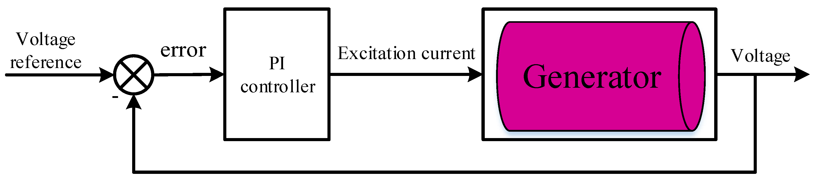
The voltage regulator is one of the ways to maintain the voltage stability of the power supply system. Its basic principle is to achieve the purpose of controlling the generator output voltage by adjusting the excitation current. Its main functions include:
Here, PI controller is designed for the two generators.
The PI controller, whose transfer function can be expressed as
where
and
are proportional coefficient and integral coefficient, respectively.
is Laplace operator.
The block diagram of PI control for a generator is shown in
Figure 5.
3.3. Intelligent Control for AC/DC Rectifiers
3.3.1. Control for AC/DC Rectifiers
Power electronics is important for the MEA [
28]. Power electronic converters are divided into four types: AC/DC rectifier, DC/DC converter, DC/AC inverter, and AC/AC transformer. Among them, AC/DC converters refer to the multi-pulse rectification technology, and the three-phase bridges are commonly used rectifier circuits.
Because the weight and volume are increased with the number of pulses in autotransformer rectifiers, a 12-pulse autotransformer rectifier unit (ATRU) is applied in this paper.
The variability of electrical loads results in a fluctuation in the DC bus voltage. In order to reduce the fluctuation, APF is used to improve the performance of ATRU.
Figure 6 shows the design of 12-pulse ATRU with APF; the DC-side parallel APF topology diagram is shown in
Figure 7;
Figure 8 shows the equivalent circuit diagram of the DC-side APF; and
Figure 9 gives the control scheme for APF-ATRU.
It can be seen from
Figure 6 that this topology is based on a 12-pulse ATRU, and two parallel APFs are in the output of the three-phase uncontrolled rectifier bridge. Since the input voltages of the two sets of three-phase uncontrolled rectifier bridges have phase difference, their output instantaneous voltages are not equal. In order to ensure normal operation, balanced reactors are used to smooth the two sets of DC voltage, so that the total output voltage meets the working conditions.
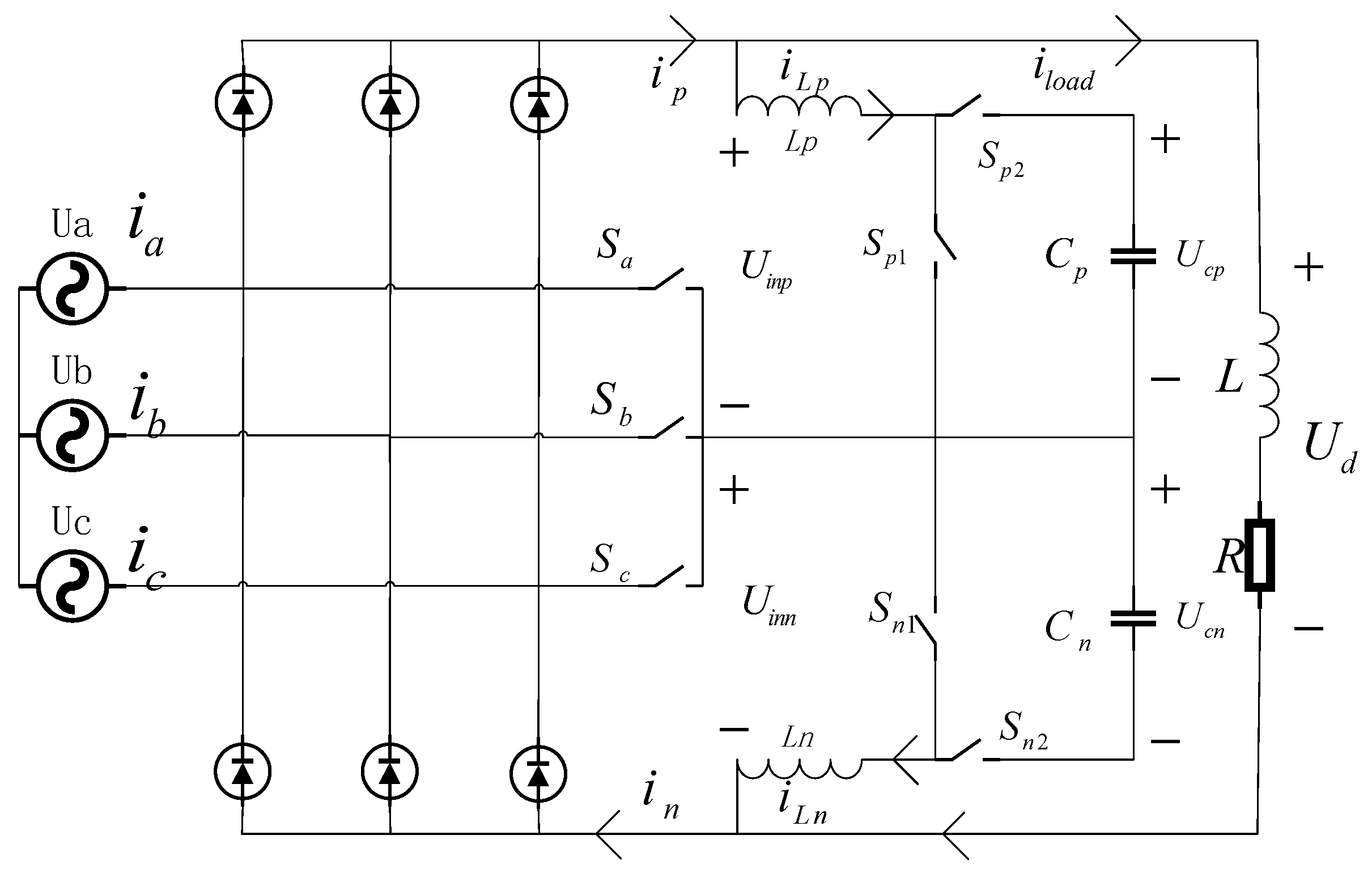
Because the 12-pulse ATRU based on DC-side parallel APF designed in this paper is composed of two three-phase bridges, in order to describe the problem conveniently, here, a three-phase bridge is shown in
Figure 7 as an example to introduce.
In
Figure 7,
,
,
,
and
,
,
,
, constitute a bidirectional dual boost circuit, together with a low-frequency bidirectional switch
,
,
constitute a main circuit of a DC-side parallel APF, where
and
are filter inductors.
,
,
,
are high-frequency switches,
and
capacitances. The low-frequency switches work at double the fundamental frequency, while the
,
,
, and
work at high frequency, and the two pairs of high-frequency switches work complementary to each other. The three low-frequency switches are only turned on one at a time, and the conduction rule is that the one at the intermediate voltage is turned on. Compared with low-frequency switching, the frequency of high-frequency switching is very high; therefore, a certain voltage conduction can be used as an example for illustration.
As shown in the equivalent circuit diagram of DC-side APF, i.e.,
Figure 8, when
and
are closed, the filter inductor is directly connected to the power supply. At this time, the power supply charges the filter inductor, namely, the inductor current increases, giving
where
,
are the voltages of
and
, respectively. Moreover,
is the voltage between point
p and
m, and
is the voltage between point
m and
n.
When
and
are closed, the voltage across the filter inductor can be expressed as:
and are the voltages of and , respectively; and are the currents through and , respectively.
It can be seen that the voltage across the inductor decreases, that is, the inductor current decreases. Similarly, when and are closed or when and are closed, the voltage across the two filter inductors increases or decreases accordingly.
From the above analysis, it can be seen that the voltage across the filter inductor can be positive or negative, and thus the inductor current can be increased or decreased, which means the current is controllable. Therefore, when proper control is applied, the circuit can be viewed as a controlled current source, thereby achieving compensation for the harmonic current of the non-linear load.
The dual-loop control scheme is used for the control of APF-ATRU. A FOPI voltage controller for the outer loop and PI current controller for the inner loop. Moreover, the multi-objective optimization algorithm based on GWO is used to optimize the control system.
Figure 9 shows the schematic diagram of the control for APF-ATRU. According to
Figure 9, GWO is used to tuning the parameters of FOPI controller, while GWO is on the basis of minimizing two performance indexes for APF-ATRU. The two performance indexes are the integral of time and absolute error (ITAE) and the total harmonic distortion (THD), respectively.
The voltage controller in outer loop is to ensure stability of voltage and provide the reference signal for the current controller. The transfer function of FOPI controller can be expressed as
where
and
are proportional coefficient and integral coefficient, respectively.
,
, and
are the designable parameters in FOPI controller, and they are optimized by GWO, as shown in
Figure 9. Compared with PI controller of integer order, PI controller of fractional order increases the integral order
.
The current controller in inner loop is to ensure that the DC-side APF can compensate the DC-side current in real time. PI controller is designed for the inner loop, with and being the designable parameters in the controller.
According to
Figure 2, there are two AC/DCs, it is supposed that the same FOPI controller parameters
,
and
in voltage outer loop, and the same PI controller parameters
,
in current inner loop are used in each APF.
3.3.2. Intelligent Optimization for Controller Parameters in AC/DC Rectifiers
In the following subsection, GWO is used to carry out controller parameter intelligent optimization for the two APF-ATRUs.
The target of optimization is to minimize DC voltage tracking error and harmonic current simultaneously. Thus, the following multi-objective performance indexes (20) are chosen, which are the ITAE performance index and the THD performance index. Because an APF-ATRU is composed of two independent rectifier bridges, actual objective functions are averages of two sets of ITAE and THD, respectively.
and
are ITAE for the voltage tracking requirement of the two APF-ATRUs, respectively.
and
are THD for the harmonic current demand of the two APF-ATRUs, respectively.
where
and
are voltage tracking of the two APF-ATRUs, respectively.
and
are the effective values of the n-th harmonic current of the two APF-ATRUs, respectively.
and
are the effective values of fundamental current of the two APF-ATRUs, respectively.
Three parameters,
,
, and
, need to be optimized. Therefore, when GWO is used to realize intelligent control for APF-ATRUs, the
described by (
13) for each
is
.
4. Virtual Synchronous Generator Based DC/AC Design
Aircraft has different loads in different flight conditions, and there are probably sudden AC loads changes, which cause both AC bus and DC bus fluctuate. These fluctuations are instantaneous. At this time, it is not enough to only control the power supply system in DC-side since there is a time lag in the voltage adjustment process. The preferred way is to have corresponding adjustment means for AC bus as well, so that the MEA electrical power system can keep the DC bus voltage in the case of sudden AC loads changes. Therefore, a suitable control method should be designed for DC/AC inverter.
The DC/AC inverter on a traditional aircraft is the aero static inverter (ASI), whose main function is to convert the electrical energy of a DC power supply into AC power for the use of electrical equipment.
With the development of MEA, the number of airborne equipment is increasing, and the power supply capacity of the power supply system is becoming larger and larger. The traditional ASI can no longer meet the requirements of large power supply capacity. Moreover, the AC power from the ASI cannot achieve closed-loop control, and thus, the voltage amplitude and frequency are susceptible to load changes.
VSG is a new inverter control strategy, which can use the energy storage device to simulate the rotor inertia and damping characteristics of synchronous generator, and improve the operation characteristics of the inverter [
34,
35,
36]. Compared with the traditional DC/AC inverter control scheme, VSG can simulate the characteristics of synchronous generator active frequency regulation and reactive power voltage regulation through control algorithm, to ensure the stability of the AC bus. At present, VSG is widely studied in micro-grid. Because MEA power system is a kind of independent micro-grid, VSG can be used to aviation field.
Therefore, VSG technology is proposed to adjust the DC/AC inverter in this paper as shown in
Figure 2, so as to insure the AC bus has satisfied performance, such as strong stability of bus voltage, current and frequency, and good fault tolerance.
The main circuit topology of DC/AC with VSG control algorithm is shown in
Figure 10.
In
Figure 10,
–
are six switch tubes; the
are equivalent to the output voltages of synchronous generator; the
are voltages output to the hybrid power system;
constitutes a filter and the midpoint voltage of the bridge arm (
) simulates the internal potential of the synchronous generator. The control system consists of power calculation, VSG control algorithm and pulse width modulation (PWM) technology.
The active and reactive power of VSG is calculated as
where
and
are obtained by coordinate transformation of
. Similarly,
and
are obtained by coordinate transformation of circuit current.
The VSG can simulate the inertia of synchronous generator, and its active frequency modulation characteristics can be expressed by the torque formula of the mechanical part of the generator as
The characteristics of reactive voltage regulation can be described as
where
and
, respectively, for set point of active power and reactive power.
is the moment of inertia of the rotor,
is on behalf of the mechanical torque given,
is the electromagnetic torque,
is damping coefficient,
refers to the rotor angle,
is for rotor angular velocity,
represents droop coefficient,
represents moment coefficient,
is for output voltage effective value,
is rated voltage effective value, and
is for modulation wave effective value.
The three-phase modulated wave can be expressed as
Figure 11 shows VSG control block diagram. There are two main parts in
Figure 11: one is the active power loop, and the other is the reactive power loop. It can be found that the active loop regulates the frequency of the output voltage, and the reactive loop outputs the amplitude of the output voltage.
5. Simulation
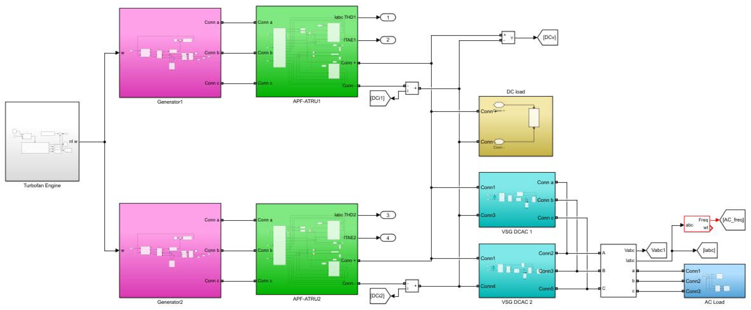
The simulation platform of MEA power control system as shown in
Figure 12. In
Figure 12, the outlets 1, 2, 3, and 4 relate to the performance indexes
,
,
, and
, respectively.
Consider that the dynamic of aircraft engine is much slower than that of AC/DC, the optimization of aircraft engine control law is separated from that of AC/DC in the simulation. After obtaining the optimized aircraft engine intelligent SMFTC law (
11) according to
Figure 4, the whole MEA power control system is optimized by GWO on the basis of
Figure 9.
5.1. Intelligent Fault-Tolerant Control on Aircraft Engine
In this subsection, simulation on a twin-shaft aircraft engine is performed to illustrate the theoretical results proposed in this paper. The linear part of the aircraft engine model used here is adopted from [
25].
According to (
6), considering (2) and based on [
25], here,
,
,
are normalized variables. They are dimensionless, and the units of them are not shown in the following simulation figures in this subsection. The matrices
A,
B,
C, and
D are
, respectively. It is supposed that the actuator faults coefficient matrix is
. Obviously, the matrix
A is Hurwitz,
is controllable,
is invertible.
It is supposed that the lumped uncertainties occur from the 2nd second. The lumped disturbance . Clearly, there are both time-vary disturbance and non-linear term in . Moreover, it is noted that there exists non-linear cross-channel interaction in , which indicates the complex dynamics of the aircraft engine.
Assume the initial deviation state vector from operating point is .
An iteration of GWO optimal result of SMFTC for aircraft engine is given in
Figure 13.
Figure 13 illustrates the wolves search preys, and there are three possible positions of preys for dominating. Therefore, users can select a satisfying
from the three possible positions.
According to
Figure 13, if users pay more attention to minimizing inputs consumption, the rightest non-dominated solution point can be chosen as the optimal point; by contrast, to choose the leftest; or give consideration to both performance indexes, to select the middle one.
Table 1 shows the chosen values of
under SMFTC and Intelligent SMFTC methods, respectively. In
Table 1, the parameters in the second row for SMFTC method are tuned by manual work through lots of attempts and can ensure the closed-loop system to be stable. While, because minimizing inputs consumption has attracted more attention in this paper, the parameters in the third row of
Table 1 are selected for the Intelligent SMFTC method, after seeking by GWO automatically.
In
Table 1 and
Table 2 and
Figure 14,
Figure 15,
Figure 16,
Figure 17,
Figure 18 and
Figure 19, “SMFTC” represents the controller without optimizing, and “Intelligent SMFTC” represents the controller with intelligent optimization by GWO.
Figure 14,
Figure 15,
Figure 16,
Figure 17 and
Figure 18 show the comparison of control performance between SMFTC and Intelligent SMFTC, when there is no lumped disturbance.
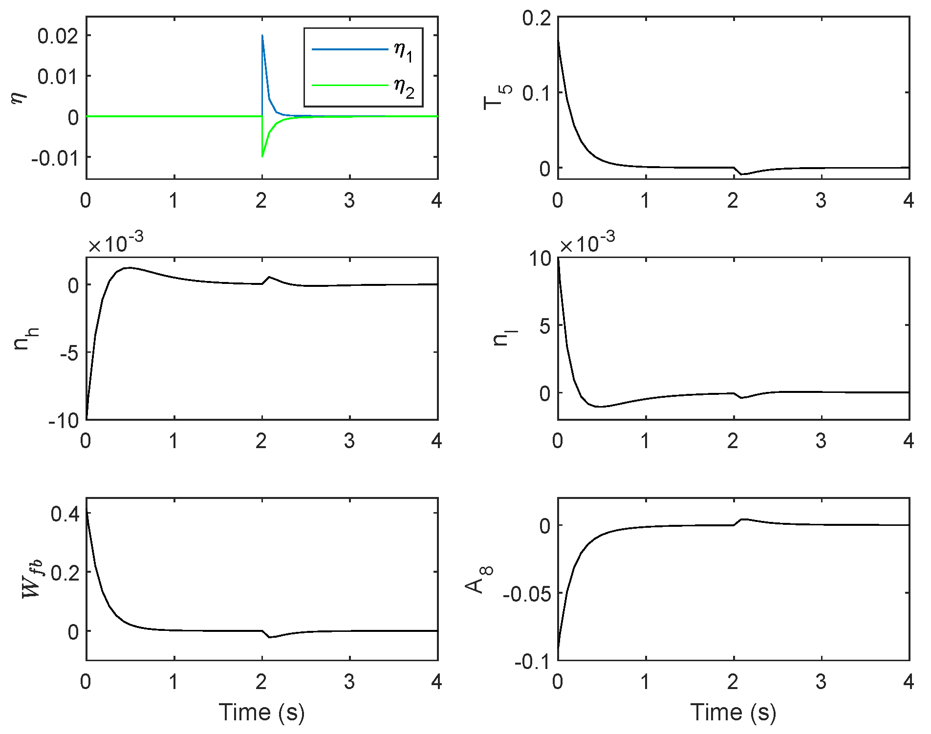
Figure 19 gives the control results of aircraft engine with lumped disturbance since the 2nd second under Intelligent SMFTC method.
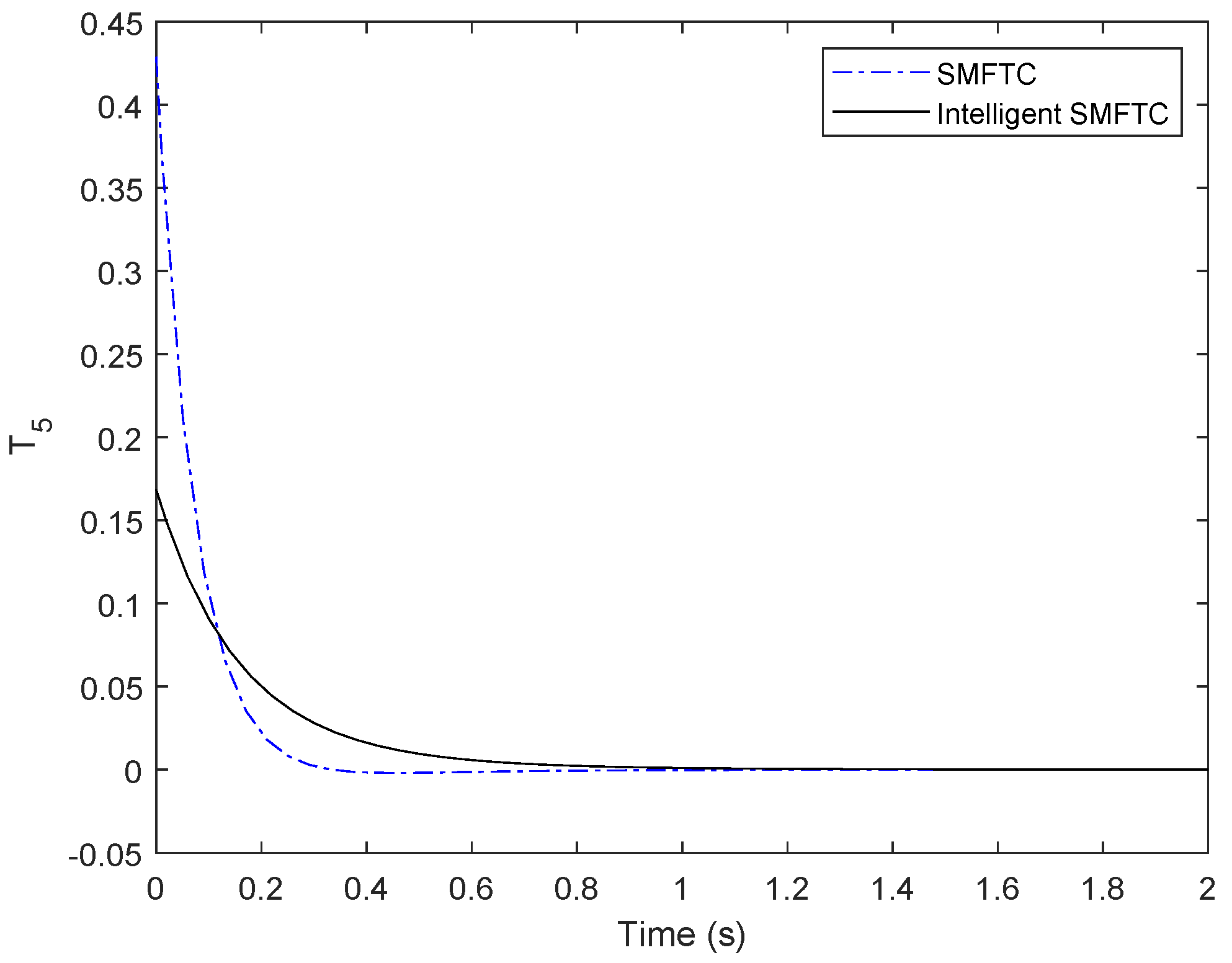
It can be seen from
Table 2 and
Figure 14,
Figure 15 and
Figure 16 that the maximum absolute values of
,
and
are decreased significantly under Intelligent SMFTC method.
Figure 17 and
Figure 18 show that the maximum absolute values of
and
are almost the same under the two control methods, with the maximum absolute values of
is a bit smaller with Intelligent SMFTC. Because the generators are driven by the low-pressure spool, it is desired that the over-shooting of
is small.
As mentioned above, minimizing inputs consumption has attracted more attention than states deviations.
Table 2 shows the sum of squared inputs are dropped greatly under Intelligent SMFTC method, the dropping percentage is
; while the sum of squared states deviations increased as small as
, the increasing percentage is
. Therefore, the optimization by GWO has realized the performance requirements.
As shown in
Figure 14,
Figure 15,
Figure 16,
Figure 17 and
Figure 18, dynamic is slower after optimizing, because minimum input consumption is considered, nevertheless, all inputs, outputs and states can be stable in 2 s, which is an acceptable setting time for aircraft engine.
Figure 19 shows the simulation results about intelligent SMFTC for aircraft engine with lumped disturbance since 2nd second. Obviously, all of
,
,
,
,
are affected little by lumped disturbance
, and are back to steady-state quickly.
5.2. Intelligent Control for the Whole MEA Power System
In this subsection, the Intelligent SMFTC for aircraft engine has been applied, and the purpose of this subsection is to determine the optimized designable FOPI parameters in voltage outer loop of APF-ATRUs, as shown in
Figure 9, and show the simulation results about the intelligent control for the whole MEA power system.
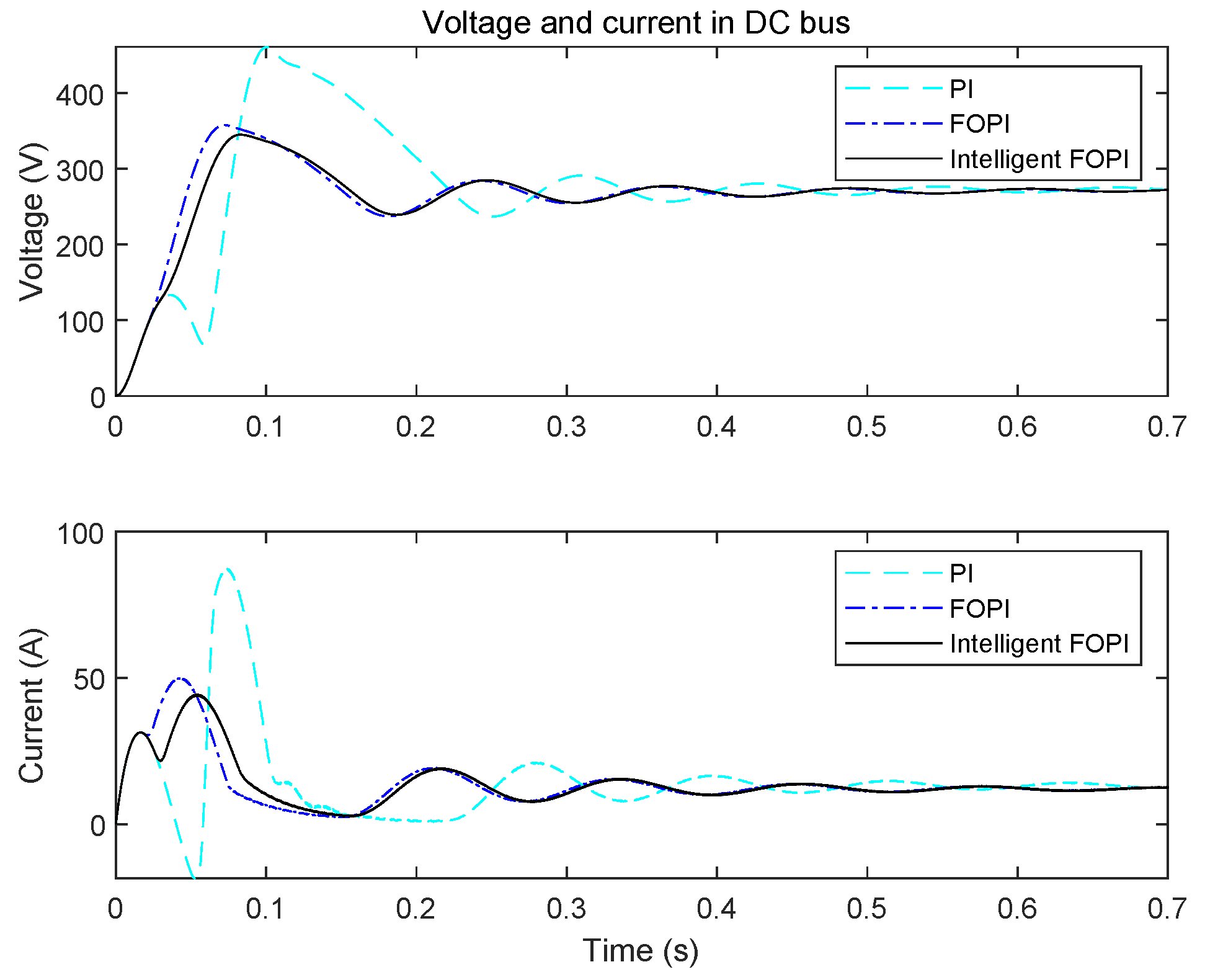
Thus,
Figure 20 gives the control effect of DC voltage and current comparison among PI, FOPI and Intelligent FOPI three controllers in 0.7 s, when APF-ATRUs are used in the MEA power system. Meanwhile, the lumped disturbance is shown in
Figure 21.
Figure 22,
Figure 23,
Figure 24 and
Figure 25 show the control effect of comparison between no APF and has APF in MEA power system for 3.8 s. Considering the similar dynamics of three phases on AC bus, the voltage, current and frequency can be compared on only one phase, as shown in
Figure 23,
Figure 24 and
Figure 25, respectively.
In order to illustrate the robustness of the MEA power system, it is supposed that:
An AC load incrementation adds into system during second. The AC load incrementation is of active power 2000 (W) and inductive reactive power 1000 (positive var). Before 0.7 s, the AC load is of active power 4000 (W) and inductive reactive power 2000 (positive var). Namely, the incrementation is of 50%;
One of DC/AC inverts failure occurs during seconds. During this period, the faulty DC/AC inverter is disconnected, and the load power is fully borne by the other DC/AC inverter.
Lumped disturbance for aircraft engine appears from 1.8 s.
The main parameters of electric components are given in
Appendix A.
For the two generators in the MEA power system, the PI controller parameters are chosen as
,
. For the two APF-ATRUs in the MEA power system, the PI controller parameters for current inner loop are chosen as
,
. Three controllers are designed for the voltage outer loop of APF-ATRUs, and the parameters of each controller is given in
Table 3.
Obviously,
Figure 20 shows that both FOPI and Intelligent FOPI controllers can let the voltage and current in DC bus have better dynamic performance than those under PI controller. The setting time is almost the same under FOPI and Intelligent FOPI controllers. However, the maximal values of overshooting in both voltage and current are the smallest under the control of Intelligent FOPI controller.
Figure 22 shows when the MEA power system does not have APF, the overshooting in DC bus is much greater than that of having APF with intelligent control. The steady-state values of voltage and current in DC bus are 270 V and 13 A, respectively. For the case, there is no APF, the maximum values of voltage is 437.2, and current is 72.11, respectively. The percentages of overshooting are
,
, respectively. For the case, there is APF with intelligent control, the maximum values of voltage is 343.2, and current is 44.85, respectively. The percentages of overshooting are
,
, respectively. Clearly, the maximum value of DC voltage drops almost 50%, and the maximum value of DC current drops almost 200%.
Moreover, it is seen that the AC load incrementation brings some fluctuation for the voltage and current of DC bus; however, the fluctuation disappears in 0.6 s after the AC load incrementation is removed. In addition, DC/AC failure changes the voltage and current of DC bus tiny. Thus, the VSG for DC/AC is effective to guarantee the stability of voltage and current in DC bus.
Although the lumped disturbance makes the low-pressure spool speed of aircraft engine change, the voltage and current of DC bus are affected little.
From
Figure 23,
Figure 24 and
Figure 25, one can find that the curves of voltage, current, and frequency in AC-side are similar, whether APF is in the MEA system or not. Namely, the performance of the AC-sides is not affected by the APF in the DC-side. Thus, for the AC-side, the VSG is important to ensure the voltage, current, and frequency are of desired performance.
Figure 23 and
Figure 25 show voltage and frequency in the AC bus are influenced by the AC load incrementation, DC/AC fault and lumped disturbance for aircraft engine little. Obviously, it is shown in
Figure 24 that current in the AC bus is increased with the increasing of AC load, and once the AC load incrementation is removed, the current is back to the former level soon.
Therefore, the proposed intelligent control method for the whole MEA power system can guarantee the aircraft engine has strong robustness, fault tolerance to actuator faults, and minimal energy consumption; the voltage and current in DC bus and AC bus have satisfying steady-state and dynamic performance, strong robustness to the sudden change of AC load, DC/AC fault and lumped disturbance happened in aircraft engine; and the frequency of AC current remains around specified value.
6. Conclusions
An intelligent FTC method is presented for a kind of MEA AC/DC hybrid electrical power system in this paper. The main features of this method include:
- -
A multi-objective optimization Intelligent SMFTC method is proposed for aircraft engine, with fault actuators being considered, to ensure that the states of aircraft engine have strong robustness and fault-tolerance performance.
- -
Intelligent FOPI controllers are designed for the AC/DC rectifiers, which are 12-pulse ATRU with APF by optimizing multiple performance indexes, so as to reduce the fluctuation in the DC bus voltage.
- -
VSG method is applied for DC/AC inverters, in order to realize that the AC-side has satisfying voltage, current, and frequency, no matter the sudden change of AC load happens or DC/AC fault occurs.
The MEA power system is considered as a holistic system, which is comprised of an aircraft engine, two electric generators, two AC/DC rectifiers, two DC/AC inverters, DC loads, and AC loads.
Simulation results verify the proposed intelligent FTC method can guarantee the whole MEA hybrid AC/DC power system has satisfying performance, such as high steady-state and dynamic performance, strong robustness, and fault tolerance.
Since the proposed method has shown high efficiency, it is advisable to consider their application to other possible MEA hybrid power systems or their components, for example, electric drives.


