Abstract
To replace highly toxic hydrazin-driven reaction control systems, a number of non-toxic alternatives are under development. These are usually referred to as “green propellants”. One candidate is the bi-propellant combination of nitrous oxide and hydrocarbons that combine good storability with a comparatively high specific impulse () at a medium to low system complexity level compared to existing hydrazine thrusters. This propellant combination was chosen because of experimentally available results with C2H4-N2O thrusters as validation data. One advantage of this fuel/oxidizer combination is that both gases are self-pressurant and that they can be used as monopropellants at a lower specific impulse with reduced model complexity. This helps the design of the propulsion system on satellites. A detailed numerical simulation of a representative thruster based on the fuel combination ethylene and nitrous oxide is presented. The numerical model is set up with a suitable kinetic reaction mechanism for the simulation of the reactive mixture in the combustion chamber. It is validated against experimental data available in the literature.
1. Introduction
A number of promising non-toxic propellants are currently under development for satellite reaction controls systems, usually referred to as “green propellants”. A summary of common design and propellant choices for green propellant thrusters can, e.g., be found in [1,2].
On the topic of “green propellants” significant effort has been put into the development of thrusters and propulsion hardware aiming to replace the toxic hydrazine thrusters, see, e.g., [1,2,3,4,5,6,7]. Green propellants are on the focus list of the European Space Agency (ESA) to replace hydrazine-based thrusters for short- and medium-duration space missions [8]. Among many options, the bipropellant combination of nitrous oxide N2O and ethylene C2H4 (Werling [9]), called HyNOx, is one promising option due to its simplicity and its relatively high specific impulse (). Up to now, mostly experimental investigations have been carried out to characterize experimentally these engines [2,9,10]. The first commercial thruster units have been built and flown in space, e.g., by Dawn Aerospace [11] or ISPtech [12]. One advantage of this fuel/oxidizer combination is that both gases are self-pressurant and they can be used as a monopropellant thruster at a slightly lower , e.g., by means of a simple cold-gas thruster. This facilitates the application on a satellite propulsion unit.
The focus of previous (mainly experimental) research on these thrusters was mainly on the development of the propulsion characteristics as well as advancing the technology readiness level of such thruster systems. In recent years, several experimental test campaigns have been conducted [2,9,10] investigating the main influence on the experimental efficiency of the thrusters, i.e., the influence of the chamber pressure, mixture ratio, residence time in the combustion chamber, chamber surface, and the injector design on the characteristic velocity . Up to now, only limited research was spent on setting up a detailed numerical model other than characterizing the thruster. The missing link is a detailed numerical simulation model, which would allow the simulation of steady-state and transient operating conditions, i.e., during startup and shutdown. Due to the main usage as reaction control thrusters, their operation is characterized by small impulses with potentially non-optimal combustion conditions during the transient phases. This might raise issues due to contamination concerns, especially for planetary missions. An experimental study [13] using a propene C3H6 nitrous oxide N2O thruster of Dawn Aerospace [11] indicated potential contamination effects especially during the startup and shutdown phase of the thruster. During these operating points, unburnt fuel/oxidizer droplets left the thruster. This supports the necessity of having a numerical model of the green-propellant thruster available to simulate and optimize these transient phases.
In this contribution, a numerical model for a representative small-scale reaction thruster developed at DLR in Lampoldshausen [2] (now commercialized by the company ISPtech) based on ethylene C2H4 and nitrous oxide N2O as fuel combination is described. The thruster configuration [2] was chosen due to its publicly available test data. This covers both use cases of a mono- and bipropellant applications: the fuel and oxidizer can either be injected premixed or separately using a coaxial injector. For the premixed case, special care has to be taken to prevent a flame flashback into the feeding system.
The numerical model presented is derived from the choice of suitable kinetic reaction mechanisms to the application of this model using a simulation of the combustion chamber. The numerical model was developed further towards transient operation conditions for which contamination effects potentially may play a significant role.
In the first section the numerical model is described used in computational fluid dynamics (CFD) focusing on premixed and non-premixed injection. The kinetic model is validated comparing ignition delay times and laminar flame speeds of the full and reduced kinetic models. This eased the choice of a simplified model for the detailed combustion chamber investigations aiming first at the application using fuel and oxidizer in a premixed injection and then its application as with a coaxial injector for which fuel and oxidizer are injected separately. The CFD model was applied to a simplified one-injector combustion chamber as well as to the experimental configuration using 16 injectors.
2. Numerical Methodology
2.1. Flow Solver
The ideal gas flow solver used was the DLR TAU code for the compressible Navier–Stokes and RANS equations. Only a brief overview is given here; detailed descriptions can be found elsewhere, for instance Gerhold [14], Schwamborn et al. [15], Mack and Hannemann [16], Hannemann [17], and Karl [18]. TAU is a hybrid grid, finite volume, compressible flow solver. In the past, it was verified for a variety of steady and unsteady flow cases, ranging from sub- to hypersonic Mach numbers with and without combustion.
The system of governing equations is solved using a Godunov-type finite volume method. Second-order spatial accuracy is obtained using MUSCL reconstruction at cell interfaces [19]. For the modeling of the turbulent terms within the RANS approach [20], a Spalart–Allmaras turbulence model [21] was applied that has shown to be a robust and reliable model for combustion chamber flows.
TAU’s finite rate chemistry model was used in thermal equilibrium. Chemical source terms were calculated from Arrhenius’ equations given by the kinetic model; backward reaction rates were calculated using the forward rates and the equilibrium constants.
The finite rate model was validated systematically and extensively by Karl [18]. Fundamental 0D computations successfully reproduced ignition delay times and explosion limits of hydrogen–oxygen combustion. Lift-off height of a supersonic combustion flame was also matched. TAU has been used in the past for rocket combustion engine simulations, e.g., cryogenic rocket engines based on H2-O2 and CH4-O2 [22,23,24] and hydrazine based thrusters by Ecker [25].
A mixture of chemically reacting fluids was governed by the compressible Navier–Stokes equations. Reynolds decomposition to total and partial densities and Favre decomposition to the remaining flow variables yield the set of equations that was solved numerically.
The species transport properties, i.e., the species laminar viscosities and thermal conductivities were estimated using the NASA-7 and NASA-9 polynomials. Their individual values were used in Wilke’s mixing rule [26] to obtain the mixture viscosity.
2.2. Kinetic Model
An overview of suitable kinetic schemes for HyNOx thrusters is given in Table 1. The GRI mechanism is the state of the art for hydrocarbon combustion and includes the nitrogen chemistry that is crucial for the HyNOx thruster. Naumann et al. [27] and Janzer et al. [28] provided a thorough validation of the kinetic scheme based on a C0–C3 type mechanism (based on combustion of methane to butane) enriched with nitrogen chemistry (called DLR SynNG + NO [28]). However, the mechanism contains more species and reactions than the GRI 3.0 and is, thus, not considered here for the application to time-consuming three-dimensional steady-state CFD investigations.

Table 1.
Overview of available kinetic models for HyNOx thrusters.
Due to the extensive kinetic mechanism, one task was to reduce the number of species and reactions for the simulation of a whole combustion chamber as each species required an additional species conservation equation in the solver. Thus, reducing the kinetic mechanism is one key factor to keep the computational cost reasonable. This is a crucial first step as the extensive kinetics mechanism is quite time-consuming for a practical three-dimensional CFD application.
3. Kinetics Reduction and Optimization
The aim was to reduce the kinetics for the specific application case. The quality of the reduction was assessed by comparing the laminar flow speeds, ignition delay times, and equilibrium temperature using a constant pressure reactor. The reactor problem was solved using the OpenSource software Cantera [30] version 2.5, which has some tools for basic chemistry reduction, i.e., it resolves the full GRI 3.0 mechanism and then sorts the reactions according to their importance. In a second step, the most important reactions are selected with their associated species. Of course, this simple optimization procedure does not imply that the resulting mechanism is valid nor does provide correct results. Thus, a validation step was needed for the reduced mechanism. This is often achieved by looking at results for constant pressure 0D-reactor simulations, in this case for the propellant combination ethylene and nitrous oxide in Figure 1.
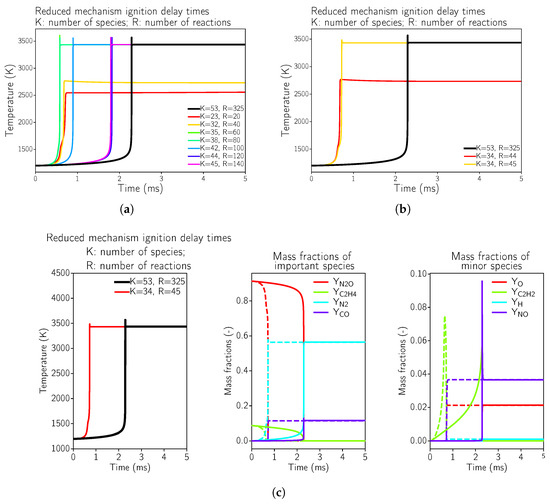
Figure 1.
Ignition delay times for reduced kinetic mechanisms in comparison to the full GRI 3.0 mechanism for N2O and C2H4 at 8 bar pressure using a reactor test case using Cantera [30]. The initial conditions were set to a temperature of 1200 K and an O/F ratio of 6.7. (a) Global view of possible mechanisms starting with the GRI3.0 [20]. (b) Minimal possible mechanism that reproduces the correct equilibrium temperature. (c) Minimal possible mechanism that reproduces the correct equilibrium temperature; comparison of GRI3.0 [20] (solid line) to the simplified mechanism (dashed line).
Due to the fact that nitrogen is part of the oxidizer (nitrous oxide is used), the nitrogen chemistry has to be considered additionally to the hydrocarbon oxidation reactions. Another key factor is the (relatively) high combustion temperature. This elevated temperature favors high-temperature nitrogen reactions which may be of low importance for other fuel–oxidizer combinations, typically used for space propulsion, e.g., hydrazine, methane, or kerosene.
It can be seen in Figure 1a,b that the highly simplified kinetics mechanisms were not even able to reproduce the equilibrium temperature of the reactive mixture, which was the case for the reaction mechanisms with 20 and 40 reactions. This implied that during the optimization process, some important reactions were neglected. Starting from 45 reactions (see Figure 1c), the equilibrium temperature was estimated correctly, but the ignition delay time was not correct. This fact might not be of such importance for steady-state simulations, as considered here. Additional species and equations were necessary for a correct estimation of the ignition delay time. In Appendix A.1, the minimally possible kinetic mechanism that reproduces the correct equilibrium temperature in the reactor test case is provided. For a steady-state approach, the main optimization criterion was to achieve the correct equilibrium combustion temperature as well as the correct equilibrium composition (of the main species).
As a showcase how a reduced reaction mechanism might affect the flame structure and the heat loads of the thruster, the minimally possible mechanism with 35 species and 45 reactions was selected (as summarized in Appendix A.1).
4. Premixed Injection
The first step was to validate the numerical model using experimental results. The aim was to quantify the thruster performance used in a premixed application, i.e., the fuel and oxidizer were injected premixed at a certain oxidizer to fuel (O/F) ratio. For this configuration, various experimental results were available [2,9,10]. The baseline combustion chamber was the one described by Werling and Bätz [10] with 16 injectors. NASA CEA [31] data is available for this chamber at the given test conditions. For a first numerical comparison one experimental test case was chosen with a short combustion chamber and a nozzle throat diameter of 5 mm, representing a characteristic combustion chamber length of as the baseline test case to validate the numerical model.
The high pressure drop, as seen in the sample pressure plot determined by Werling and Bätz [10], in the fuel feed line was related to a porous structure that prevents flame flashback into the feed system, which was a crucial component of experimental hardware. This porous structure was not modeled in the numerical model; thus, the numerical model starts directly at the entry into the combustion chamber. In order to account for the influence of the porous structure on the feed system in the model, a reduced inlet pressure was prescribed.
4.1. Simplified One-Injector Chamber
As a first step to gain understanding of this new propellant type, a simplified one-injector combustion chamber with the same injection conditions was considered. This allowed us to consider an axis-symmetric grid for a faster and more detailed investigation into the influence of the chemical mechanism. As extensive numerical experience with this propellant combination is lacking, a numerical prestudy is advantageous for a parameter sensitivity study. By using this approach, our numerical model for this propellant combination was validated before applying it to a realistic combustion chamber design.
The one-injector combustion chamber was scaled such that the combustion chamber volume was representative of the 16-injector chamber, with one single injector on the center-line. While the injection conditions, the injector geometry, and the chamber pressure were kept the same, the cross-section of the chamber and the nozzle throat diameter were scaled to account the reduced injector mass flow when using only one injector. The characteristic chamber length was kept the same to ensure that the single flame was fully enclosed in the chamber.
The operating conditions for the scaled one-injector chamber are shown in Table 2. At the injector, a subsonic inflow boundary condition was assumed at which the premixed mass flow g/s (in the experiment, a mass flow of g/s for all injectors was used) was prescribed with an O/F ratio of 6.7. At the nozzle throat, a supersonic outlet condition was used. The injector wall, as well as the faceplate, were treated as viscous adiabatic walls as the main heat losses are expected to be at the combustion chamber walls and the nozzle wall. These walls were treated using a wall heat flux estimation based on a one-dimensional heat conduction
with a material dependent conduction coefficient (assumed to be Wm−1K−1), a wall thickness of d (assumed to be mm), and a temperature difference between the outside and inside temperature. For the numerical model, a constant outside temperature of 300 K was assumed and computed the one-dimensional heat conduction equation in radial direction for each boundary point. This simple wall heat flux treatment was a good compromise between and isothermal wall boundary condition and a fully coupled combustion chamber simulation including heat transfer simulation into the chamber wall structure. It is also worth noting that during the experiments, the combustion chamber was not cooled and the maximum operation time of the thruster was about 10 s. This operational mode was chosen to avoid structural damage to the combustion chamber. Generally, such thrusters are usually fired in pulsed mode with different burst lengths.
Table 2.
Operating conditions for the scaled one-injector chamber.
The chosen axisymmetric mesh has in total 171,000 nodes with refinements in the region of the injector as well as the combustion region. All walls are refined such to achieve a on all walls.
4.1.1. Solution Using the Full GRI 3.0 Mechanism
In a first step, the reference solution for this combustion chamber using the full GRI 3.0 [20] reaction mechanism with 53 species and 325 reactions was computed.
The flow solution in the combustion chamber is visualized in Figure 2; a validation of the global combustion chamber parameters in comparison to CEA [31] and the experiments is given in Table 3. The wall pressure distribution (see Figure 3b) in the combustion chamber of 7.8 bar fitted well to the experimentally measured pressure and the CEA estimation. The combustion temperatures in the combustion chamber fit to the integral ones estimated by CEA. Additional experimental measurement data was not available in the literature [2,9,10]. A distribution of the wall heat flux is shown in Figure 3a.
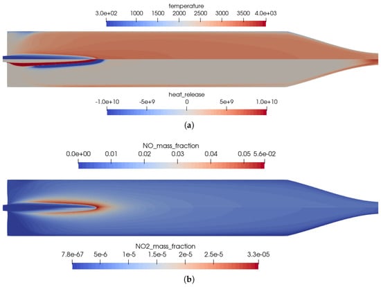
Figure 2.
Flow solution inside the one-injector combustion chamber using the full GRI 3.0 mechanism [20]. (a) Top: temperature distribution inside the combustion chamber; Bottom: heat release due to chemistry. (b) Top: distribution of the NO mass fraction; Bottom: distribution of the NO2 mass fraction.
Table 3.
Comparison of global parameters for the one-injector combustion chamber. is the characteristic velocity of the rocket engine.
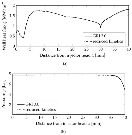
Figure 3.
Wall heat flux and wall pressure distributions at the combustion chamber wall; mm: combustion chamber wall, mm nozzle wall. (a) Wall heat flux. (b) Wall pressure distribution.
The main advantage of the numerical model was that the completely resolved flow domain provided additional insights to the flow and kinetic processes that happen inside the combustion chamber. These detailed effects were not visible in the experiments due to only limited instrumentation available in the experimental model, i.e., with pressure sensors in the combustion chamber walls without optical access to the combustion chamber. Nevertheless, several conclusions can be drawn from the numerical solution:
- The flames were relatively short and covered the first third of the combustion chamber length.
- High combustion temperatures in the flame promote the creation of , especially in the reaction zones, see Figure 2b.
- Two main reaction zones can be identified in Figure 2a: as expected, directly next to the flame front in which fuel and oxidizer reacted. An additional region with recombination reactions can be seen in the nozzle throat and close to the wall due to the cold walls.
- The kinetic process in the combustion was not complete, and thus, by-products were still present in the nozzle exhaust. The shock pattern in the nozzle causes an additional heating of core flow which might provoke additional chemical reactions downstream of the nozzle. Also, post-combustion with the external air flow could be possible. This effect is, however, not considered here.
- Note that the nozzle extension geometry downstream of the throat was not known from the literature. Therefore, a generic nozzle shape was assumed. Due to flow chocking in the nozzle throat, the assumed nozzle shape will not have any upstream influence.
4.1.2. Mesh Sensitivity Study with the Full GRI 3.0 Mechanism
To investigate the mesh sensitivity of the solution, the baseline test case on the mesh stated previously is compared to a mesh with an axisymmetric mesh of double the size with the GRI 3.0 reaction mechanism. The baseline mesh has a mesh size of 171,000 nodes while the refined mesh has a size of 850,000 nodes. The effect of the mesh sensitivity study is shown in Figure 4 comparing the field values of temperature, NO mass fraction, and heat release on both meshes.
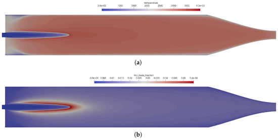
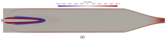
Figure 4.
Mesh sensitivity study comparing the field solution for the fine mesh (top) to the baseline mesh (bottom). (a) Temperature distribution in the thruster. Top: using the fine mesh; bottom: using the baseline mesh. (b) Distribution of the NO mass fraction. Top: using the fine mesh; bottom: using the baseline mesh. (c) Distribution of the heat release in the kinetics. Top: using the fine mesh; bottom: using the baseline mesh.
The mesh convergence study showed that the mesh resolution of the baseline mesh is sufficient to capture all flow physics in the numerical model. Thus, in the following studies, the baseline mesh is used for further investigations.
4.1.3. Solution Using the Reduced Kinetics
One possible reduced mechanism was investigated in a reactor framework with 35 species and 45 reactions; the reduced mechanism is summarized in Appendix A.1.
A comparison of the field solution in the combustion chamber is plotted in Figure 5a for the temperature and in Figure 5b for the mass fractions of species NO as one marker species for the flame. The flame structure was not influenced by the reduced kinetics mechanism, but it had influences on the chemical composition as expected and the maximum flame temperatures. Using the reduced mechanism, the flame was minimally longer.
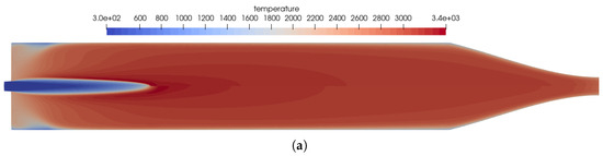
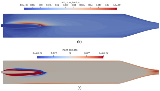
Figure 5.
Influence of the chemical kinetics onto the flow solution for the one-injector combustion chamber using the coaxial injector. (a) Temperature distribution in the thruster. Top: using the full GRI 3.0 reaction mechanism [20]; bottom: using the reduced kinetics with 35 species. (b) Distribution of the NO mass fraction. Top: using the full GRI 3.0 reaction mechanism [20]; bottom: using the reduced kinetics with 35 species. (c) Distribution of the heat release in the kinetics. Top: using the full GRI 3.0 reaction mechanism [20]; bottom: using the reduced kinetics with 35 species.
Two very important combustion chamber design parameters are the wall heat flux and the combustion chamber pressure shown in Figure 3a,b, respectively. Both were only slightly modified when the reduced mechanism was used. From the plot of the heat release Figure 5c, the following conclusions can be drawn: the main kinetic pathways as well as the recombination zone close to the walls was resolved by the GRI and the simplified mechanisms. This resulted in similar thermal loads on the combustion chamber walls as seen in Figure 3a. The range was well within the experimentally stated values of 0.5–3.6 MW/m2 [10]. The main difference can be observed in the additional reaction zone in the nozzle throat: this zone was not captured by the reduced mechanism and, thus, led to lower thermal loads in the nozzle section.
Hence, the reduced mechanism was an affordable alternative capable of reproducing the flame structure in the combustion chamber at a lower computational cost. Due to the importance of the nitrogen chemistry at these conditions, the reduced mechanism still contained 35 species. For the application in CFD cases, the number of species should be reduced even further, as for each species, an additional conservation equation has to be solved.
4.2. Full-Scale 16-Injector Chamber Used in Experiments
The modeling strategy of the one-injector combustion chamber was applied to the full 16-injector combustion chamber that was investigated experimentally. The results of the experimental test campaigns are summarized elsewhere [2,9,10]. In those, the effects of combustion chamber length, chamber pressure, O/F ratio, and nozzle throat diameter were investigated; the main parameters influencing the performance of the thrusters. For the numerical rebuilding of this campaign, the GRI 3.0 [20] mechanism was applied for the full 16-injector configuration.
In the combustion chamber, 16 injectors were distributed as follows: one injector on the center-line, five injectors on the inner ring rotated at an angle of 54°, and ten injectors on the outer ring with a rotation angle of 36°. This injector layout was chosen such to avoid symmetries in the injector head. For the numerical rebuilt of such an injector, one, therefore, has to compute the whole combustion chamber because simplifications due to symmetries cannot be applied. This is probably due to a design pattern of injection heads that tries to avoid symmetries due to possible combustion instabilities.
The same numerical setting for the inflow, outflow, and wall boundary conditions was applied as for the one-injector case mentioned above. The combustion chamber and nozzle walls are resolved with a structured boundary layer mesh with a resolution of . The operating conditions are detailed in Table 4. The resulting mesh has approximately 1.7 Mio nodes for the 3D simulation.
Table 4.
Operating conditions for the 16-injector chamber taken from Werling and Bätz [10].
An overview of the flow features of the 16-injector combustion chamber is shown in Figure 6a from the OH iso-contours. It can be observed that the central flame was a bit longer compared to the outer flames. This was a direct effect of the flame–flame interaction in the combustion chamber. The outer flames were bent slightly towards the centerline. These were typical effects of the flame–flame interactions. Overall, the flame lengths were shorter compared to the single-injector test case.
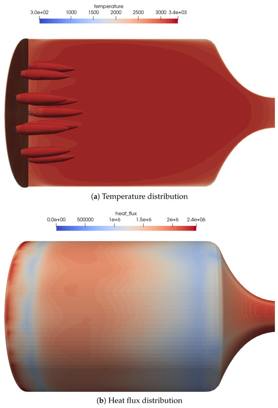
Figure 6.
Flow distribution in the 16-injector chamber: (a) Temperature distribution on the centerplane as well as the OH mass fraction iso-contours of to visualize the flame zone. (b) Heat flux distribution on the combustion chamber walls. The streaks of the outer injector ring can be seen quite well in the heat flux distribution.
In the heat flux distribution on the combustion chamber wall (see Figure 6b), the position of the outer flames can be recognized by streaks in the wall heat flux. The global heat flux distribution was similar to the one of the one-injector test case and within the range stated by Werling and Bätz [10].
A quantitative assessment of the flame lengths is performed in Figure 7, comparing the density values on the centerline. The outer injectors cause the flames to be shorter compared to the one injector case, and thus, the density value was decreasing earlier.
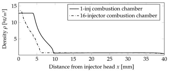
Figure 7.
Comparison of the density distribution on the centerline for the non-premixed case.
5. Non-Premixed Injection
The application of the ethylene and nitrous oxide fuel/oxidizer combination for a bipropellant thruster was subsequently analyzed, i.e., the fuel and oxidizer are not premixed and injected by a coaxial injector. Because there are no injector designs published, a coaxial injector with an diameter of 0.5 mm for N2O and an outer diameter of 0.65 mm for C2H4 was assumed. This was done to retain the injection properties, i.e., the velocity in the injector tube, in a similar range compared to the premixed application. The operating conditions are summarized in Table 5 and the mass flow of the case with the premixed injector in Table 2 were kept the same. Similarly, the geometry of the combustion chamber as well as the numerical model was not changed.
Table 5.
Operating conditions for the scaled one-injector chamber with a coaxial injector.
5.1. Scaled One-Injector Chamber with Coaxial Injector
For the investigations, the simplified one-injector combustion chamber was used as mentioned above, but with a different injector. For the bipropellant investigations, a coaxial injector was used. This design is favorable to prevent flame flashbacks that are an issue of premixed propellant injectors. Some additional mechanical design methods are necessary to prevent that, e.g., through a porous membrane. From a kinetic point of view, the approach is similar.
In a first step, the full GRI 3.0 [20] mechanism was applied and cross-checked in a second stage with the reduced mechanism. The global comparison by integral combustion chamber values using the coaxial injector is presented in Table 6. The mesh for the axisymmetric case with coaxial injector has about 190,000 nodes due to the increased resolution needed in the coaxial injector.
Table 6.
Comparison of global parameters for the one-injector combustion chamber.
5.1.1. Solution Using the Full GRI 3.0 Mechanism
The reference solution for this combustion chamber was computed using the full GRI 3.0 [20] reaction mechanism with 53 species and 325 reactions. The difference to the simulation mentioned previously was only the injection process. In the non-premixed case, a coaxial injector is used with separate injection of fuel and oxidizer. This changed the results in some distinct ways, which can be seen by comparing Figure 2 and Figure 8.
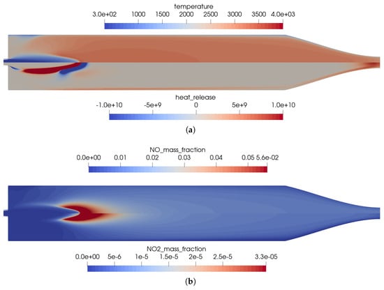
Figure 8.
Flow solution inside the one-injector combustion chamber obtained with the full GRI 3.0 mechanism [20] using a coaxial injector. (a) Top: temperature distribution inside the combustion chamber; bottom: heat release due to chemistry. (b) Top: distribution of the NO mass fraction; bottom: distribution of the NO2 mass fraction.
- Due to the non-premixed injection of fuel and oxidizer, both streams had to mix to start the reactions. This resulted in a longer flame liftoff distance.
- In the first injection phase, endothermic mixing reactions were taking place before exothermic reactions took over.
- The injection in the coaxial injector caused a stronger mixing of the fuel and oxidizer that resulted in an overall shorter flame length.
The distribution of the wall heat flux on the combustion chamber wall, see also the non-premixed single injector case in Figure 3a, is shown in Figure 9a. Compared to the premixed injection, the heat loads on the wall were comparable. Similar values for the combustion chamber pressure (see Figure 9b) were achieved regardless of the choice of the injector.
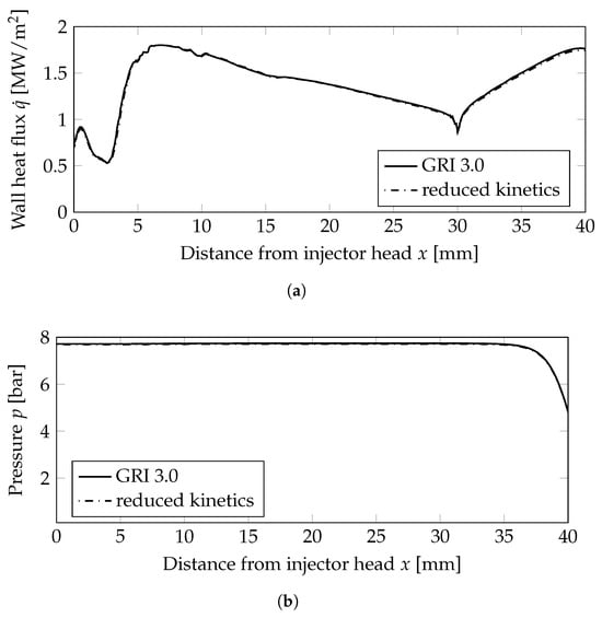
Figure 9.
Wall heat flux and wall pressure distributions on the combustion chamber wall; mm: combustion chamber wall, mm nozzle wall. (a) Wall heat flux. (b) Wall pressure distribution.
5.1.2. Solution Using the Reduced Chemical Reaction Mechanism
The effects of the simplified kinetic model are shown in Figure 10 by visualizing the main differences between the chemical kinetic models. The main differences between the two models are as follows:
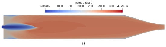
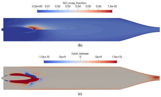
Figure 10.
Influence of the chemical kinetics onto the flow solution for the simplified one-injector combustion chamber using a premixed injection. (a) Temperature distribution in the thruster. Top: using the full GRI 3.0 reaction mechanism [20]; bottom: using the reduced kinetics with 35 species. (b) Distribution of the NO mass fraction. Top: using the full GRI 3.0 reaction mechanism [20]; bottom: using the reduced kinetics with 35 species. (c) Distribution of the heat release in the kinetics. Top: using the full GRI 3.0 reaction mechanism [20]; bottom: using the reduced kinetics with 35 species.
- In Figure 10b, the reduced mechanism failed to predict the endothermic process of NO creation at the flame front. This resulted in a slightly longer flame for the reduced mechanism compared to the full GRI 3.0 mechanism.
- The same differences regarding the reactions in the nozzle can be seen for the coaxial injector case as well. In this region, the reduced reaction set is not optimized to represent all physical effects at the low pressure in the nozzle.
5.2. Full-Scale 16-Injector Chamber
As a demonstration for the numerical model, the full combustion chamber with 16 coaxial injectors was simulated. The operating conditions are summarized in Table 7. A similar mesh geometry regarding combustion chamber dimensions was chosen for the three-dimensional case with premixed injection. Compared to the previous simulation the 16 coaxial injectors were resolved, i.e., the center flow of N2O with the round injector around of C2H4. Each injector was modeled with a short channel to include boundary layer effects. As the baseline chemical model, the GRI 3.0 [20] mechanism was applied with 53 species and 325 reactions. The resulting mesh has approximately 9.0 Mio nodes for the 3D simulation including the 16 coaxial injectors.
Table 7.
Operating conditions for the 16-injector chamber with coaxial injectors.
An overview of the flow features for the combustion chamber using coaxial injectors is shown in Figure 11a. The coaxial injection causes stronger mixing of the oxidizer and fuel. This resulted in a very different flame topology, with shorter and thicker flames.
Figure 11.
Flow distribution in the 16-injector chamber. (a) Temperature distribution on the center plane as well as the OH mass fraction iso-contours of to visualize the flame zone. (b) Heat flux distribution on the combustion chamber walls. The streaks of the outer injector ring can be seen quite well in the heat flux distribution.
The footprint of the outer flames can be recognized by the streaks in the wall heat flux distribution on the combustion chamber wall, see Figure 11b. The global heat flux distribution was similar to the simplified one-injector case.
A quantitative comparison of the flame lengths is presented in Figure 12, comparing the density values on the centerline. The outer injectors caused the flames to be shorter compared to the one-injector case, and thus, the density value was decreasing earlier.
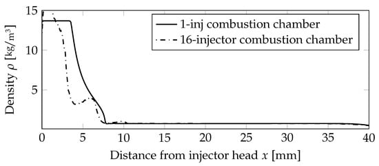
Figure 12.
Comparison of the density distribution on the centerline for the premixed case.
6. Summary and Conclusions
In this contribution, the validation of a numerical model for the simulation of small thrusters based on the fluid combination nitrous oxide and ethylene was described. This fuel/oxidizer combination has been investigated experimentally and is a possible replacement for the hazardous hydrazine thrusters. Although this type of propellant has been investigated quite some time, little is known about the detailed processes inside the combustion chamber. The focus has been on the experimental testing and the increase of the technology readiness level. In this study, the use of this fuel/oxidizer combination with two injection modes was investigated: either with a premixed injector or an injection using a coaxial injector. This numerical model was validated against CEA and experimental data. The estimated pressure in the combustion chamber fitted within 3% to the measured value.
This numerical investigation provided additional insights to the combustion processes within green propellant thrusters based on nitrous oxide; something that is not easily accessible in experiments. The flame structure and the chemical processes inside the combustion chamber were numerically elucidated. Based on a detailed chemical kinetics model the experimentally measured combustion chamber pressure for both the scaled one-injector combustion chamber, as well as the 16-injector combustion chamber was confirmed. Two different injector designs were investigated, one premixed single-injector configuration and one coaxial injector with separate injection of fuel and oxidizer. The latter has the advantage that it does not need a mechanical design method that prevents flame flashback. The developed numerical model was able to reproduce available measurement data with good accuracy to literature data.
The limiting factor of the numerical model was the extensive GRI 3.0 reaction mechanism with 53 species and 325 reactions. The first numerical results were promising and reproduced the experimental results, but a suitable reduced kinetic mechanism is needed for further investigations. Other open points are the startup and shutdown transient phases. When used in a reaction control system, these thrusters are usually operated in an intermittent mode with short pulses. Experimental investigations in vacuum facilities have shown that especially in these operation modes, the reaction is not complete and may lead to contamination.
Author Contributions
S.F. wrote the main manuscript text, T.E. provided tools for the analysis of the chemistry. All authors contributed to the discussion. All authors have read and agreed to the published version of the manuscript.
Funding
Open Access funding enabled and organized by Projekt DEAL. This research was funded by German Aerospace Center (DLR) in the framework of the project AMADEUS (Advanced Methods for Reusable Aerospace Vehicle DEsign Using Artificial Intelligence and Interdisciplinary Numerical Simulation) focusing on the qualification and advancement of the DLR flow solver TAU for liquid rocket thrust chamber applications. The financial support of the DLR Space Research Programmatic is highly appreciated.
Data Availability Statement
The raw data supporting the conclusions of this article will be made available by the authors on request.
Conflicts of Interest
The authors declare no conflicts of interest.
Abbreviations
The following abbreviations are used in this manuscript:
| CC | Combustion chamber |
| CEA | Chemical equilibrium compositions program by NASA |
| CFD | Computation Fluid Dynamics |
| DLR | German Aerospace Center |
| EOS | Equation of state |
| ESA | European Space Agency |
| NASA | National Aeronautics and Space Administration |
| O/F-ratio | Oxygen-to-fuel ratio |
| Sc | Schmidt number |
| characteristic velocity of combustion chamber | |
| Thickness of combustion chamber wall, m | |
| Specific impulse, | |
| Characteristic combustion chamber length, m | |
| p | Pressure, Pa |
| Combustion chamber pressure, Pa | |
| T | Temperature, K |
| Injection temperature, K | |
| Characteristic combustion chamber volume, m3 | |
| Mass fractions | |
| Heat transfer coefficient, |
Appendix A
Appendix A.1. Reduced Kinetic Mechanisms
The simplified kinetic mechanism for the fuel/oxidizer combination C2H4 and N2O for a pressure of 8 bar is shown in Table A1.
Table A1.
Simplified kinetic mechanism for the fuel/oxidizer combination C2H4 and N2O for a pressure of 8 bar. Units in mol, J, m, s.
Table A1.
Simplified kinetic mechanism for the fuel/oxidizer combination C2H4 and N2O for a pressure of 8 bar. Units in mol, J, m, s.
| Rate Constants | |||||||
|---|---|---|---|---|---|---|---|
| No. | Reaction | A | n | E | |||
| 1 | ⇌ | 2.6500e+10 | −0.67 | 7.1300e+04 | |||
| 2 1 | ⇌ | 5.6000e+06 | 0.00 | 1.0042e+04 | |||
| 3.8000e+28 | −7.27 | 3.0208e+04 | |||||
| A = 0.7507, T3 = 98.5, T1 = 1302.0, T2 = 4167.0 | |||||||
| 3 | ⇌ | 4.7600e+01 | 1.23 | 2.9288e+02 | |||
| 4 | ⇌ | 2.7000e+07 | 0.00 | 1.4853e+03 | |||
| 5 | ⇌ | 3.8700e+08 | 0.00 | 7.8994e+04 | |||
| 6 2 | ⇌ | 7.9100e+10 | 0.00 | 2.3439e+05 | |||
| 6.3700e+08 | 0.00 | 2.3698e+05 | |||||
| 7 | ⇌ | 3.3700e+07 | 0.00 | 0.0000e+00 | |||
| 8 | ⇌ | 5.0000e+09 | 0.00 | 7.2509e+04 | |||
| 9 | ⇌ | 3.6000e+00 | 2.00 | 1.0460e+04 | |||
| 10 | ⇌ | 3.8700e-02 | 2.70 | 2.6192e+04 | |||
| 11 | ⇌ | 3.3600e+07 | 0.00 | 1.6108e+03 | |||
| 12 3 | ⇌ | 7.4000e+07 | −0.37 | 0.0000e+00 | |||
| 2.3000e+06 | −0.90 | −7.1128e+03 | |||||
| A = 0.7346, T3 = 94.0, T1 = 1756.0, T2 = 5182.0 | |||||||
| 13 | ⇌ | 1.7000e+12 | 0.00 | 1.2305e+05 | |||
| 14 | ⇌ | 1.2500e+01 | 1.83 | 9.2048e+02 | |||
| 15 4 | ⇌ | 1.8700e+11 | −1.00 | 7.1128e+04 | |||
| 16 | ⇌ | 5.8000e+06 | 0.00 | 6.2760e+03 | |||
| 17 | ⇌ | 3.5700e-02 | 2.40 | −8.8282e+03 | |||
| 18 5 | ⇌ | 2.2000e+10 | −2.00 | 0.0000e+00 | |||
| 19 6 | ⇌ | 5.4000e+05 | 0.45 | 7.6149e+03 | |||
| 6.0000e+29 | −7.62 | 2.9162e+04 | |||||
| A = 0.9753, T3 = 210.0, T1 = 984.0, T2 = 4374.0 | |||||||
| 20 | ⇌ | 2.1000e+09 | −0.69 | 1.1924e+04 | |||
| 21 | ⇌ | 5.0000e+06 | 0.00 | 6.2760e+03 | |||
| 22 | ⇌ | 5.0600e+07 | 0.00 | 0.0000e+00 | |||
| 23 | ⇌ | 1.3250e+00 | 2.53 | 5.1212e+04 | |||
| 24 7 | ⇌ | 4.4800e+07 | −1.32 | 3.0962e+03 | |||
| 25 | ⇌ | 5.7400e+01 | 1.90 | 1.1473e+04 | |||
| 26 | ⇌ | 1.0800e+08 | 0.00 | 1.3012e+04 | |||
| 27 | ⇌ | 1.1300e+01 | 2.00 | 1.2552e+04 | |||
| 28 | ⇌ | 1.3500e+01 | 2.00 | 7.9496e+03 | |||
| 29 | ⇌ | 2.1600e+02 | 1.51 | 1.4351e+04 | |||
| 30 8 | ⇌ | 1.0600e+08 | −1.41 | 0.0000e+00 | |||
| 31 | ⇌ | 3.6500e+08 | −0.45 | 0.0000e+00 | |||
| 32 | ⇌ | 1.1260e+07 | −0.76 | 0.0000e+00 | |||
| 33 | ⇌ | 1.3200e+08 | 0.00 | 1.5062e+03 | |||
| 34 | ⇌ | 3.8000e+07 | −0.36 | 2.4267e+03 | |||
| 35 | ⇌ | 1.5000e+12 | −1.00 | 7.1128e+04 | |||
1 CO = 1.5, CO2 = 2.0, H2 = 2.0, H2O = 6.0. 2 CO = 1.5, CO2 = 2.0, H2 = 2.0, H2O = 6.0. 3 CO = 1.5, CO2 = 2.0, H2 = 2.0, H2O = 6.0. 4 CO = 1.5, CO2 = 2.0, H2 = 2.0, H2O = 0.0. 5 H2 = 0.73, H2O = 3.65. 6 CO = 1.5, CO2 = 2.0, H2 = 2.0, H2O = 6.0. 7 CO = 1.5, CO2 = 2.0, H2 = 2.0, H2O = 6.0. 8 CO = 1.5, CO2 = 2.0, H2 = 2.0, H2O = 6.0.
Table A2.
Simplified kinetic mechanism for the fuel/oxidizer combination C2H4 and N2O for a pressure of 8 bar. Units in mol, J, m, s.
Table A2.
Simplified kinetic mechanism for the fuel/oxidizer combination C2H4 and N2O for a pressure of 8 bar. Units in mol, J, m, s.
| Rate Constants | |||||||
|---|---|---|---|---|---|---|---|
| No. | Reaction | A | n | E | |||
| 36 | ⇌ | 8.0000e+07 | 0.00 | 0.0000e+00 | |||
| 37 | ⇌ | 6.7000e+00 | 1.83 | 9.2048e+02 | |||
| 38 9 | ⇌ | 4.8650e+05 | 0.42 | −7.3429e+03 | |||
| 1.0120e+30 | −7.63 | 1.6125e+04 | |||||
| A = 0.465, T3 = 201.0, T1 = 1773.0, T2 = 5333.0 | |||||||
| 39 | ⇌ | 9.0000e+03 | 1.00 | 2.7196e+04 | |||
| 40 | ⇌ | 1.6500e+08 | 0.00 | 0.0000e+00 | |||
| 41 | ⇌ | 5.4000e+07 | 0.00 | 0.0000e+00 | |||
| 42 | ⇌ | 5.0000e+07 | 0.00 | 0.0000e+00 | |||
| 43 | ⇌ | 2.2500e+01 | 1.70 | 1.5899e+04 | |||
| 44 | ⇌ | 3.4300e+03 | 1.18 | −1.8702e+03 | |||
| 45 | ⇌ | 6.9400e+00 | 2.00 | 7.9496e+03 | |||
9 CO = 1.5, CO2 = 2.0, H2 = 2.0, H2O = 6.0.
Appendix A.2. Reaction Path Diagram
A visualization of the reaction path diagram is shown in Figure A1 following the species nitrogen. This visualization shows the main reaction paths for the hydrocarbon–nitrous oxide oxidizer–fuel combination.

Figure A1.
Reaction path diagram for the GRI 3.0 reaction mechanism following the species N.
Figure A1.
Reaction path diagram for the GRI 3.0 reaction mechanism following the species N.

References
- Nosseir, A.E.S.; Cervone, A.; Pasini, A. Review of State-of-the-Art Green Monopropellants: For Propulsion Systems Analysts and Designers. Aerospace 2021, 8, 20. [Google Scholar] [CrossRef]
- Werling, L.; Lauck, F.; Dobusch, J.; Gritzka, M.A.; Stratmann, V.; Merz, F.; Hörger, T.; Teuffel, P.J.; Braune, L. From Lampoldshausen to Space: DLR Spin-off InSpacePropulsion Technologies and the Development Status of Green Propellant Thrusters Based on H2O2 and N2O. In Proceedings of the 10th European Conference for Aeronautics and Space Sciences (EUCASS), Lausanne, Switzerland, 9–13 July 2023. [Google Scholar]
- Carlotti, S.; Maggi, F. Evaluating New Liquid Storable Bipropellants: Safety and Performance Assessments. Aerospace 2022, 9, 561. [Google Scholar] [CrossRef]
- Aggarwal, R.; Patel, I.; Sharma, P. Green propellant: A study. Int. J. Latest Trends Eng. Technol. 2015, 6, 83–87. [Google Scholar]
- Remissa, I.; Jabri, H.; Hairch, Y.; Toshtay, K.; Atamanov, M.; Azat, S.; Amrousse, R. Propulsion systems, propellants, green propulsion subsystems and their applications: A review. Eurasian Chem.-Technol. J. 2023, 25, 3–19. [Google Scholar] [CrossRef]
- Sahoo, J.P.; Choudhary, D.N.; Praveen, M. Experimental Evaluation and Design of Propulsion System for Cubesat: N2o and C2h4 as Green Bipropellant. J. Aerosp. Sci. Technol. 2022, 74, 126–140. [Google Scholar]
- Chai, W.S.; Liu, L.; Sun, X.; Li, X.; Lu, Y.Y. An Overview of Green Propellants and Propulsion System Applications: Merits and Demerits. In Recent Advancements in Green Propulsion: Green Propellants for Micropropulsion Systems; Springer: Berlin/Heidelberg, Germany, 2024; pp. 3–32. [Google Scholar]
- European Space Agency. Green Propellants Need to Match Performance Benchmarks: Ferran Valencia Bel Interview. Available online: https://www.esa.int/Space_Safety/Clean_Space/Green_propellants_need_to_match_performance_benchmarks_Ferran_Valencia_Bel_interview (accessed on 13 December 2013).
- Werling, L.K.; Hörger, T.; Manassis, K.; Grimmeisen, D.; Wilhelm, M.; Erdmann, C.; Ciezki, H.K.; Schlechtriem, S.; Richter, S.; Torsten, M.; et al. Nitrous oxide fuels blends: Research on premixed monopropellants at the german aerospace center (DLR) since 2014. In Proceedings of the AIAA Propulsion and Energy 2020 Forum, Virtual, 24–28 August 2020; p. 3807. [Google Scholar]
- Werling, L.; Bätz, P. Parameters Influencing the Characteristic Exhaust Velocity of a Nitrous Oxide/Ethene Green Propellant. J. Propuls. Power 2022, 38, 254–266. [Google Scholar] [CrossRef]
- Dawn Aerospace. Green Propulsion for Any Satellite. Available online: https://www.dawnaerospace.com/green-propulsion (accessed on 13 December 2013).
- InSpacePropulsion Technologies GmbH. High-Performance, Affordable and Green in-Space Propulsion. Available online: https://isptech.space/ (accessed on 13 December 2013).
- Buntrock, L.J.; Grabe, M.; Fischer, H. Contamination assessment of a freely expanding green propellant thruster plume. Proc. Iop Conf. Ser. Mater. Sci. Eng. 2023, 1287, 012004. [Google Scholar] [CrossRef]
- Gerhold, T. Overview of the hybrid RANS code TAU. In MEGAFLOW-Numerical Flow Simulation for Aircraft Design; Springer: Berlin/Heidelberg, Germany, 2005; pp. 81–92. [Google Scholar]
- Schwamborn, D.; Gerhold, T.; Heinrich, R. The DLR TAU-Code: Recent applications in research and industry. In Proceedings of the ECCOMAS CFD 2006: Proceedings of the European Conference on Computational Fluid Dynamics, Egmond aan Zee, The Netherlands, 5–8 September 2006; European Community on Computational Methods in Applied Sciences (ECCOMAS); Delft University of Technology: Delft, The Netherlands, 2006. [Google Scholar]
- Mack, A.; Hannemann, V. Validation of the unstructured DLR-TAU-Code for Hypersonic Flows. AIAA 2002, 3111, 2002. [Google Scholar]
- Hannemann, V. Numerische Simulation von Stoß-Stoß-Wechselwirkungen Unter Berücksichtigung von Chemischen und Thermischen Nichtgleichgewichtseffekten. Ph.D. Thesis, University of Göttingen, Göttingen, Germany, 1997. [Google Scholar]
- Karl, S. Numerical Investigation of a Generic Scramjet Configuration. Ph.D. Thesis, University of Dresden, Dresden, Germany, 2011. [Google Scholar]
- Van Leer, B. Towards the ultimate conservative difference scheme. V. A second-order sequel to Godunov’s method. J. Comput. Phys. 1979, 32, 101–136. [Google Scholar] [CrossRef]
- Smith, G.P.; Golden, D.M.; Frenklach, M.; Moriarty, N.W.; Eiteneer, B.; Goldenberg, M.; Bowman, C.T.; Hanson, R.K.; Song, S.H.; Gardiner, W.C., Jr.; et al. GRI-MECH 3.0. Available online: http://www.me.berkeley.edu/gri_mech (accessed on 13 December 2013).
- Spalart, P.R.; Allmaras, S.R. A one equation turbulence model for aerodynamic flows. AIAA J. 1992, 94, 439. [Google Scholar]
- Fechter, S.; Horchler, T.; Karl, S.; Hannemann, K.; Suslov, D.; Hardi, J.; Oschwald, M. Efficient handling of cryogenic equation of state for the simulation of rocket combustion chambers. In Proceedings of the Non-Ideal Compressible Fluid Dynamics for Propulsion and Power: Selected Contributions from the 2nd International Seminar on Non-Ideal Compressible Fluid Dynamics for Propulsion & Power, NICFD 2018, Bochum, Germany, 4–5 October 2018; Springer: Berlin/Heidelberg, Germany, 2020; pp. 19–30. [Google Scholar]
- Fechter, S.; Horchler, T.; Karl, S.; Hannemann, K. Investigation of rans turbulence models for cryogenic rocket combustion chambers. In Proceedings of the 8th European Conference for Aeronautics and Space Sciences (EUCASS), Madrid, Spain, 1–4 July 2019. [Google Scholar]
- Perakis, N.; Haidn, O.J.; Eiringhaus, D.; Rahn, D.; Zhang, S.; Daimon, Y.; Karl, S.; Horchler, T. Qualitative and quantitative comparison of RANS simulation results for a 7-element GOX/GCH4 rocket combustor. In Proceedings of the 2018 Joint Propulsion Conference, Cincinnati, OH, USA, 9–11 July 2018; p. 4556. [Google Scholar]
- Ecker, T.; Fechter, S.; Grabe, M. Modelling of Hydrazine droplet evaporation and combustion in small rocket thrusters. In Proceedings of the 9th Edition of the 3AF International Conference on Space Propulsion 2024, Glasgow, UK, 20–23 May 2024; pp. 1–13. [Google Scholar]
- Wilke, C. A viscosity equation for gas mixtures. J. Chem. Phys. 1950, 18, 517–519. [Google Scholar] [CrossRef]
- Naumann, C.; Kick, T.; Methling, T.; Braun-Unkhoff, M.; Riedel, U. Ethene/nitrous oxide mixtures as green propellant to substitute hydrazine: Reaction mechanism validation. Int. J. Energetic Mater. Chem. Propuls. 2020, 19, 65–71. [Google Scholar] [CrossRef]
- Janzer, C.; Richter, S.; Naumann, C.; Methling, T. Green propellants as a hydrazine substitute: Experimental investigations of ethane/ethene-nitrous oxide mixtures and validation of detailed reaction mechanism. CEAS Space J. 2022, 14, 151–159. [Google Scholar]
- Kathrotia, T.; Riedel, U.; Seipel, A.; Moshammer, K.; Brockhinke, A. Reaction Mechanism for C1-C4 Hydrocarbon Oxidation Including Chemiluminescence and C3 Submechanism. Available online: https://www.dlr.de/de/vt/ueber-uns/abteilungen/abteilung-chemische-analytik-und-kinetik/reaktionsmechanismen/mech-thermo-tran_kathrotiaetal2012_c1-c4-plus-chemlum-chemkinformat.txt (accessed on 13 December 2013).
- Goodwin, D.G.; Moffat, H.K.; Schoegl, I.; Speth, R.L.; Weber, B.W. Cantera: An Object-oriented Software Toolkit for Chemical Kinetics, Thermodynamics, and Transport Processes. Version 3.0.0. 2023. Available online: https://www.cantera.org (accessed on 13 December 2013).
- McBride, B.J. Computer Program for Calculation of Complex Chemical Equilibrium Compositions and Applications; NASA Lewis Research Center: Cleveland, OH, USA, 1996; Volume 2. [Google Scholar]


Disclaimer/Publisher’s Note: The statements, opinions and data contained in all publications are solely those of the individual author(s) and contributor(s) and not of MDPI and/or the editor(s). MDPI and/or the editor(s) disclaim responsibility for any injury to people or property resulting from any ideas, methods, instructions or products referred to in the content. |
© 2026 by the authors. Licensee MDPI, Basel, Switzerland. This article is an open access article distributed under the terms and conditions of the Creative Commons Attribution (CC BY) license.