Abstract
To investigate the influence of injector recess depth on the combustion characteristics of air heaters, high-speed shadowgraph imaging technology combined with numerical simulation was employed. Targeting a tripropellant coaxial direct-flow single injector, three test cases with recess depths of 0 mm, 5 mm, and 10 mm were designed to systematically study the ignition process, flame propagation characteristics, quasi-steady combustion, and flow field evolution mechanisms. Experimental results indicate that the recessed structure can expand the liquid mist distribution range before ignition: the dimensionless spray width ratios of the 5 mm and 10 mm recess cases are increased by 57.5% and 64.9% respectively compared to the non-recessed case, with an obvious “saturation effect” observed. Injectors with recess exhibit the characteristic of “jet head priority ignition”, which shortens the ignition time and improves ignition efficiency. The 5 mm shallow recess case achieves the optimal combustion stability with the smallest chamber pressure fluctuation (±0.1 MPa). Although the 10 mm deep recess enhances near-field mixing and combustion intensity, it tends to induce flame oscillation and combustion instability. Simulation results verify the experimental observations: the recess depth regulates droplet atomization, component mixing, and combustion heat release processes by altering the recirculation zone range, velocity gradient, and gas–liquid momentum exchange efficiency. This research provides experimental and theoretical support for the structural optimization of injectors in combustion-type air heaters.
1. Introduction
Hypersonic vehicles have become a frontier core research direction pursued by major aerospace powers worldwide due to their strategic value in national defense and aerospace fields. Ground test and measurement of vehicles are crucial links to accurately verify key indicators such as aerodynamic performance and structural strength, which require the construction of a uniform incoming flow test system capable of precisely reproducing critical parameters such as Mach number, total enthalpy, and total pressure under flight conditions. As the core equipment for regulating incoming flow parameters, the performance of air heaters directly determines the reliability of test data [1,2,3]. Currently, common air heating methods at home and abroad mainly include regenerative heating, arc heating, combustion heating, and shock wave heating. Regenerative heating achieves heat exchange through alternating heat storage and release of heat storage bodies with high heat exchange efficiency; arc heating generates high temperature through arc discharge to rapidly obtain extremely high temperatures; combustion heating heats air by releasing heat from fuel combustion, featuring mature technology and a wide application range; shock wave heating realizes rapid temperature rise by compressing air through shock waves, which is often used in hypersonic-related scenarios [4,5,6,7,8].
From the perspective of working principles, combustion-type air heaters have significant technical similarities with liquid rocket engines [9,10,11]. In the operation of liquid rocket engines, propellants undergo key processes such as atomization and fragmentation, evaporation and mixing, and efficient and stable combustion. As the core component for propellant atomization, the structural design and working characteristics of injectors directly affect subsequent mixing efficiency and combustion stability. Gas–liquid coaxial injectors are commonly used in air heaters, and the recess length is a key structural parameter of gas–liquid coaxial injectors. It is directly related to the propellant mixing process and the initial fragmentation position of droplets. Appropriate recess can reserve mixing space and improve combustion efficiency, while excessive recess is prone to causing uneven combustion near the wall and carbon deposition. Therefore, in-depth research on the influence of recess length on injector performance and engine combustion characteristics is of great practical significance.
Scholars have conducted relevant research on the impact of injector recess length on atomization, mixing, and combustion processes. First discovered in the liquid-centered gas–liquid coaxial injectors in the former Soviet Union in the 1970s [12], self-excited oscillation is related to injection parameters and key structural parameters such as gas/liquid momentum ratio, injection pressure drop, Reynolds number, inner injector recess length, and injector aspect ratio. Nunome et al. [13,14] conducted cold flow tests on transparent cavity-recessed coaxial shear injectors and found that with the increase of recess, water and nitrogen can trigger the liquid fragmentation mode to transition from fibrous to super-pulsating fragmentation under specific conditions, causing intense fragmentation and changing the flow from non-blocking to blocking. Kim et al. [15,16] investigated the hydrodynamic instability in the cavity region of shear coaxial injectors, focusing on the internal injector instability of gas–liquid shear coaxial components in liquid rocket engines, and discovered the Kelvin–Helmholtz instability mechanism and “self-oscillation” phenomenon induced by gas–liquid velocity discontinuity, identifying the fundamental frequencies under multiple operating conditions. The Japan Aerospace Exploration Agency found in the research of liquid oxygen/methane engines that the recess length of the injector liquid oxygen tube is crucial for the stability of the trailing shear layer. Shortening the recess length can inhibit the premature mixing of the liquid oxygen jet and the air annular flow, reducing the coupling risk between the vortex shedding frequency and the combustion chamber acoustic mode [17,18]. German scholar Gröning et al. [19] further pointed out that when the ratio of recess length to the tangential acoustic wavelength of the combustion chamber is 0.25, it is prone to exciting transverse rotating mode instability. Canino et al. [20] studied the vortex shedding phenomenon in recessed injectors and found through calculating the airflow of the splitter plate that the vortex shedding frequency usually increases with the increase of distance. Japanese scholar Matsuyama et al. [21] performed large eddy simulation on the P8 combustion chamber of the German Aerospace Center and found that adjusting the length of the engine injector can excite high-frequency transverse acoustic oscillations in the combustion chamber, and the acoustic oscillations inside the injector couple with those in the combustion chamber to induce high-frequency combustion instability. Tsohas et al. [22,23,24,25,26,27] found through numerical simulation that the coupling between the vortex shedding frequency in the recessed chamber and the natural acoustic frequency of the injector is the main cause of self-excited oscillation. As the recess length increases, the vortex shedding energy at the exit of the liquid oxygen injector gradually dominates the flow instability. The construction of a hot test bench shows that injector recess can change the flame shape and the distribution of combustion heat release near the injection panel, and the recirculation zone formed on the outer wall of the recessed region interacts with the vortex shed from the injector exit plane region, making the flow field more complex.
Ding et al. [28] explored through simulation that the recess of the oxygen injector in hydrogen–oxygen propellants shortens the combustion distance, advances the combustion surface, and has a significant impact on combustion efficiency. Sun et al. [29] established a theoretical analysis model for the recess depth of hydrogen–oxygen coaxial injectors and found that the flow coefficient of hydrogen–oxygen injectors decreases with the increase of recess depth; the flow coefficient of hydrogen injectors decreases with the increase of mixture ratio, while the flow coefficient of oxygen injectors shows the opposite trend. It is confirmed that the recess depth improves combustion efficiency by optimizing the propellant atomization and mixing processes. Wang et al. [30] found in the single-injector model experiment of gas oxygen/kerosene rocket engines that with the increase of injector recess length, it has a damping effect on longitudinal high-frequency combustion instability but cannot eliminate it; when the combustion chamber length is at certain values, the influence of recess length on combustion stability can be ignored, and the influence of combustion chamber length on longitudinal high-frequency combustion instability is more significant than that of recess length. Wang et al. [31] found in the gas–gas coaxial direct-flow injector that the recess distance of the central oxygen injector has a weak influence on the flame length, but can significantly promote the mixing of propellant components, improve combustion efficiency, and enhance flame stability, and the combustion efficiency gradually increases with the increase of recess distance. When there is no recess, the temperature of the flame stabilization point in the recirculation zone is low and the area is small, which is prone to flame instability. Yang et al. [32] investigated the influence of recess length on the internal flow and spray characteristics of gas–liquid swirl coaxial injectors from both theoretical and experimental aspects, and established a calculation model for the optimal recess length. Li et al. [33] found in the liquid-centered swirl coaxial injector that the cavity length is a key parameter to excite self-pulsation, which affects the spray cone angle, droplet size, and distribution, and has a significant combined effect with the gas–liquid mass ratio. At low gas–liquid mass ratios, the Sauter mean diameter (SMD) of droplets increases with the increase of cavity length; at high gas–liquid mass ratios, the diameter first increases and then decreases, and the SMD of droplets decreases with the decrease of gas–liquid mass ratio.
Based on existing research findings, relevant explorations have mainly focused on the field of liquid rocket engines, with coaxial direct-flow injectors using binary propellants (gas–liquid or gas–gas) as the primary research objects. However, for the operating conditions of hypersonic ground tests—such as high enthalpy, high pressure, and rapid flow field changes—the coupling mechanism between recess length and combustion efficiency, combustion heat release, as well as combustion stability has not been systematically revealed. Additionally, the effects of different recess depths on ignition mode transition, liquid mist diffusion laws, and other aspects remain unclear, and these research gaps cannot meet the precise design requirements of combustion-type air heaters.
As the core equipment for hypersonic vehicle ground tests, the primary function of combustion-type air heaters is to heat a large amount of room-temperature air to the designed total temperature with a small amount of fuel, thereby providing the same incoming flow conditions for vehicles as those in high altitude. As a key structure, the injector is crucial for the reproduction accuracy of incoming flow parameters. Therefore, conducting targeted research holds significant engineering value and academic significance. This study focuses on a tripropellant (air/liquid oxygen/alcohol) coaxial direct-flow single injector, adopting a combination of experimental and numerical simulation methods to systematically investigate the effects of three recess depths (0 mm, 5 mm, 10 mm) on liquid mist diffusion characteristics, ignition mode evolution, combustion stability, and flow field evolution laws. It clarifies the inherent coupling mechanism between recess depth and combustion characteristics, ultimately providing experimental support and a theoretical basis for the optimal structural design of injectors in combustion-type air heaters.
2. Experimental System
2.1. Overview of Subscale Air Heater Model
The air heater test rig adopted in this study shares the same core hardware architecture as the subscale model reported in our previous work [34]. This test rig is composed of four key components (Figure 1): a head module integrating the injector and a tripropellant coaxial direct-flow single injector, an optical combustion chamber (equipped with an 85 × 35 mm2 quartz viewing window for flow field visualization via high-speed shadowgraph imaging), an extended combustion chamber, and a tail nozzle. The internal cross-section of the combustion chamber measures 141 × 45 mm2, with the lengths of the first-stage chamber and the extended chamber set to 348 mm and 315 mm, respectively.
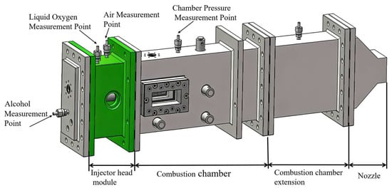
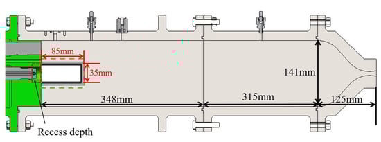
Figure 1.
Schematic diagram and combustion chamber dimension section view of subscale air heater.
To investigate the effect of injector recess depth on combustion characteristics, three sets of injectors with recess depths of 0 mm, 5 mm, and 10 mm were designed in the head module for comparative tests. Notably, only a single injector located on the central axis was employed for each experiment in this study. The head module was also equipped with dedicated measurement points for real-time monitoring of the parameters of air, liquid oxygen, and alcohol propellants. Meanwhile, a pressure measurement point was arranged on the wall of the optical combustion chamber to capture the in situ combustion pressure dynamics of the chamber. The overall layout of the test rig, dimensions of key components, and all measurement locations are clearly marked in Figure 1. Among them, temperature is detected by a PT100 thermal resistor (accuracy: ±0.5% F.S.); conventional pressure is collected via a piezoresistive pressure sensor (accuracy: ±0.5% F.S.); the mass flow rate of air is measured with a turbine flowmeter, while the mass flow rates of liquid oxygen and alcohol are determined using mass flowmeters (the accuracy of all flowmeters is ±0.5% F.S.). The detailed cross-sectional views of the injectors with different recess depth configurations are presented in Figure 2.
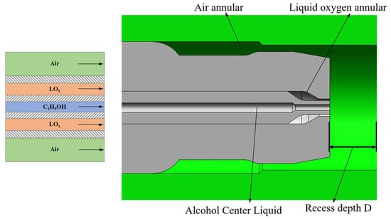
Figure 2.
Schematic diagram of tripropellant coaxial direct-flow injector structure and medium channels.
To investigate the influence of injector recess depth on flame structure, the baseline operating conditions were consistent with the benchmark case (I-2) in our prior research [34]. Specifically, the mass flow rates of the tripropellants were fixed at 502.46 g/s (air), 117.76 g/s (liquid oxygen), and 39.12 g/s (alcohol), and the nominal chamber pressure was maintained at 1.2 MPa. The structural characteristics of the cavity are quantitatively characterized by the recess depth D between the injector and the injector base. The specific test operating parameters corresponding to different recess depths D are detailed in Table 1.

Table 1.
Thermal test operating parameters of air heater.
2.2. Optical Observation Instruments
A dedicated optical observation system was built for the test, and its optical path layout is shown in Figure 3. Background light imaging technology was adopted for flow field observation, whose imaging principle is similar to the shadow method, mainly relying on the brightness difference between the background light source and the observation target to generate clear images. The background light uses an LED surface light source (white light), which is converted into red background light by adding a red film filter; the effective light-emitting area of the LED light source is 100 × 200 mm2, and the maximum output power can reach 72 W, which can provide stable and uniform illumination conditions for flow field observation. In addition, to track the dynamic evolution law of the flame during the thermal test, high-speed photography technology was introduced to focus on monitoring key dynamic parameters such as flame structure morphology, development process, and stability characteristics. In the image acquisition process, the blue–green channel of the high-speed camera is specially used to capture flame radiation signals to reflect the temperature distribution and combustion intensity of the flame; the red channel focuses on the extraction of spray images, thereby realizing the synchronous observation of spray and flame characteristics.
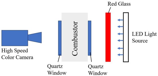
Figure 3.
Background light source.
3. Experimental Results and Discussion
3.1. Test Timing and Pressure Diagram
The time-node control scheme for the hot test process is illustrated in Figure 4 (the abscissa in the figure represents the absolute time during the test). Prior to conducting the hot test, considering that heat transfer between the pipe wall and cryogenic liquid oxygen (LOX) as it flows through the pipeline from the storage tank to the air heater can cause partial vaporization of LOX, it is necessary to open the LOX precooling valve in advance to precool the main LOX pipeline. This ensures that LOX maintains a liquid state when entering the combustion chamber. The precooling of LOX is performed in two steps: first, low-pressure precooling of the main LOX pipeline before the ignition sequence; second, high-pressure precooling immediately before ignition during the test. As shown in Figure 5, significant temperature fluctuations occur when LOX initially enters the pipeline between the precooling pre-injection valve and the injector. After 10 s, the LOX temperature stabilizes below −160 °C, following which the hot test ignition is initiated.
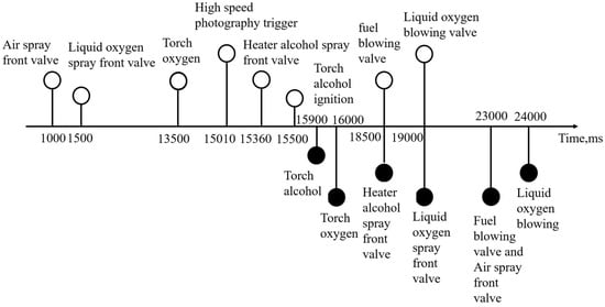
Figure 4.
Thermal test timing diagram [34].
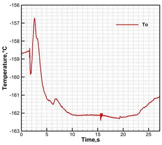
Figure 5.
Liquid oxygen pre-cooling pipeline temperature diagram.
In the formal test phase, the start-up sequence of key valves and equipment is as follows: the air pre-injection valve is opened at t = 1000 ms; the LOX pre-injection valve is opened at t = 1500 ms; the torch oxygen valve is opened at t = 13,500 ms; the high-speed photography equipment is activated 350 ms before the opening of the alcohol pre-injection valve; and the spark plug of the torch igniter completes discharge ignition at t = 15,500 ms. Due to the close installation distance between the pre-injection pressure measurement point and the spark plug of the torch igniter, electromagnetic signals generated during ignition interfere with pressure data, resulting in slight oscillations in the pressure measurements.
The pressure variation law can be clearly observed from the pressure time history of key measuring points in the combustion chamber corresponding to the non-recessed injector I-0 (Figure 6), where Pc, Po, Pf, and Pa denote the combustion chamber pressure, LOX pre-injection pressure, alcohol pre-injection pressure, and air pre-injection pressure, respectively. During the pre-injection phase (t < 15 s), the pressures of LOX and air stabilize at 2–3 MPa, while the combustion chamber pressure and alcohol pre-injection pressure build up to 0.4 MPa. At the ignition phase (t = 15.5 s), after ignition is triggered, the combustion chamber pressure rapidly rises to 1.2 MPa as the combustion reaction proceeds. In the stable phase (16 s < t < 18.5 s), the combustion chamber pressure basically reaches the design value of 1.2 MPa. These observations indicate that the test system operates in line with design expectations under the non-recessed injector condition.
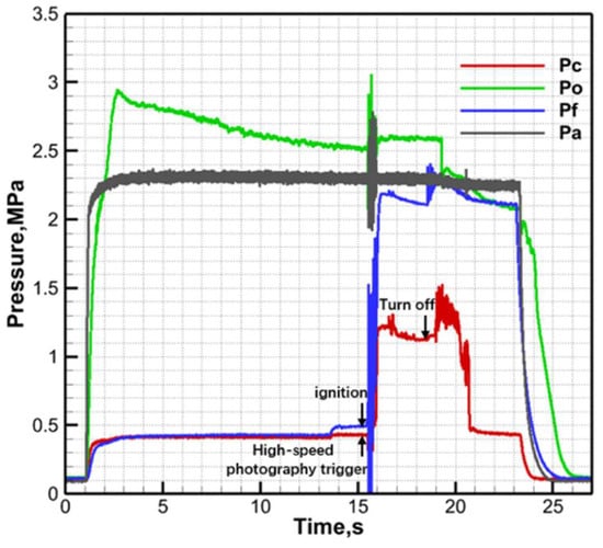
Figure 6.
Pressure time history of key measuring points under baseline condition I-0 [34].
3.2. Ignition Process Analysis
This section takes the non-recessed condition I-0 as the research object to systematically analyze the ignition start-up process and flow field evolution characteristics of the air heater. Ignition is officially triggered at t = 15,500 ms, and the internal flow field state of the combustion chamber at this time is shown in Figure 7(1),(2): it can be seen that the injector exit end face is completely covered by dense liquid oxygen spray, forming an obvious liquid mist accumulation phenomenon. This phenomenon is mainly because after the liquid oxygen enters the combustion chamber, the jet surface evaporates rapidly, and the liquid oxygen at the gas–liquid interface vaporizes violently due to rapid heat transfer. At the same time, under the shear action of the air flow, large-scale unstable fluctuations gradually develop on the surface of the liquid oxygen jet. With the continuous growth and stretching of the unstable waves, the liquid oxygen jet gradually turns into continuous liquid filaments, which move downstream of the combustion chamber under the entrainment of the air flow, and finally present a spray morphology with a smooth surface, blurred boundaries, and fibrous textures. During the initial ignition stage of t = 15,500–15,550 ms, the liquid oxygen spray continuously accumulates in the injector exit area under the dual action of flash evaporation and air recirculation, providing a material basis for the subsequent ignition reaction.
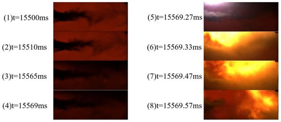
Figure 7.
Ignition process of non-recessed coaxial injector (I-0, D = 0 mm) [34].
After ignition is triggered, the hot gas injected by the torch igniter rapidly diffuses into the combustion chamber, causing the local ambient temperature to rise rapidly, thereby promoting the violent evaporation of alcohol and liquid oxygen. From the flow field images in Figure 7(3),(4), it can be clearly observed that dense liquid mist has formed in the recirculation zones on both sides of the injector panel outside the observation window, indicating that the mixing degree of fuel and oxidizer is gradually improved. There is a time difference of 69.27 ms in the transmission of the ignition signal. Until t = 15,569.27 ms, as shown in Figure 7(5), an obvious ignition glow first appears in the flammable recirculation zone above the combustion chamber inside the observation window, marking the official start of the combustion reaction. Subsequently, the ignition flame rapidly propagates along the nozzle axis under the drive of the air flow and is ejected outward. The dynamic development process of the flame morphology is shown in Figure 7(6)–(8).
From the overall experimental results, the ignition processes of the three injectors I-0, I-1, and I-2 show highly similar evolution laws, all following the phased development mode of “formation of high-speed jet spray—torch hot gas-driven evaporation—accumulation of dense liquid mist near the injector panel—ignition start—flame ejection from the nozzle”. Among them, the specific ignition processes of the I-1 and I-2 injectors can be directly observed through the timing images in Figure 8 and Figure 9, and their phase characteristics are consistent with those of the I-0 injector, further verifying the universality of the ignition mechanism of this type of injector. In terms of ignition timing accuracy, the maximum deviation of the ignition signal trigger time among the I-1, I-2, and I-0 injectors is only 5 ms, which is much smaller than the time control error threshold of the test system and within the allowable engineering range, indicating that the ignition response of the three injectors is consistent.
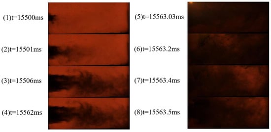
Figure 8.
Ignition process of shallow recess coaxial injector (I-1, D = 5 mm).
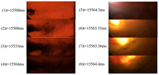
Figure 9.
Ignition process of deep recess coaxial injector (I-2, D = 10 mm).
However, significant differences can be found by comparing the flow field states before ignition: the widths of the dense liquid mist formed by the three injectors before ignition start are obviously different. To accurately quantify this difference, 500 transient spray images of each injector before ignition were time-averaged to obtain an approximate steady-state conical spray morphology. Based on the averaged spray images, the atomization widths of the I-0, I-1, and I-2 injectors were extracted as 11.38 mm, 17.94 mm, and 18.79 mm, respectively, indicating that the atomization widths of I-1 and I-2 are significantly larger than that of I-0. The dimensionless spray width ratio is defined as the ratio of the atomization width to the inner diameter of the injector base sleeve, i.e., RR = L/ΦD, where D is 26.6 mm, L is the recess amount, and ΦD is the inner diameter of the central oxygen injector. Based on this formula, the dimensionless spray width ratios of the three injectors can be calculated as shown in Table 2. From the calculation results, compared with the I-0 injector, the dimensionless spray width ratios of the I-1 and I-2 injectors are increased by 57.5% and 64.9%, respectively; while the dimensionless spray width ratio of I-2 is only increased by 4.7% compared with I-1. This indicates that in the initial stage of increasing the recess amount (from I-0 to I-1), the dimensionless spray width ratio increases significantly, but when the recess amount continues to increase (from I-1 to I-2), the increase rate slows down obviously. The nearly 60% dimensionless ratio difference between I-1 and I-0 indicates that reasonably increasing the recess amount can expand the liquid mist distribution range before ignition; while the only 4.7% ratio difference between I-2 and I-1 suggests that there is a “saturation effect” in the regulation of spray diffusion by the recess amount.
Table 2.
Calculation results of dimensionless spray width ratio RR for each injector.
3.3. Flame Propagation Process
Taking the non-recessed operating condition I-0 as the research object, the ignition flame propagation and combustion stabilization process were analyzed in detail. The flow field characteristics and flame morphology evolution of this process can be interpreted by combining the timing images in Figure 10.
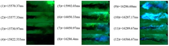
Figure 10.
Ignition flame propagation of non-recessed injector (I-0, D = 0 mm) [34].
- Initial ignition stage: Local ignition and weak flame maintenance stage (corresponding to Figure 10(1),(2))
In the initial stage of ignition start-up, during the injection process, the alcohol jet is wrapped and sheared by the high-flow air jet, and only a small amount of alcohol is entrained into the flammable recirculation zone near the injector panel. Therefore, the hot gas injected by the torch igniter only successfully ignites the flammable recirculation zone in the upper half of the combustion chamber observation window. However, due to the low alcohol concentration in this zone, the ignition flame fails to achieve full-chamber ignition of the combustion chamber and only forms a small-scale combustion locally (Figure 10(1),(2)). With the rapid consumption of alcohol droplets and alcohol vapor in the recirculation zone, the flame gradually attenuates, and finally only a weak yellow flame is maintained in a small area outside the observation window. Although this weak flame does not extinguish, it cannot drive full-chamber combustion, and becomes a “kindling source” for subsequent secondary ignition, providing an energy basis for combustion restart.
- 2.
- Flame development stage: Recirculation zone ignition and jet tail ignition stage (corresponding to Figure 10(3)–(6))
Under the continuous action of the “kindling source”, the combustion chamber pressure and local temperature rise. The sudden temperature rise accelerates the vaporization and evaporation processes of liquid oxygen and alcohol sprays, and the gas–liquid interface becomes blurred due to rapid phase change (Figure 10(3),(4)), forming a large amount of combustible mixture. At the same time, the entrainment effect of the recirculation zone is significantly enhanced, which entrains a large amount of liquid oxygen and alcohol mixture into the combustion zone, making the flame volume in the upper half of the observation window gradually expand. Subsequently, the tail region of the jet spray is successfully ignited by the flame in the recirculation zone, and the flame morphology transitions from dense liquid mist to continuous linear shape (Figure 10(5),(6)). At this stage, the flame color changes from initial yellow to pale blue, and the appearance of the blue flame indicates that the mixing uniformity of ethanol and liquid oxygen is significantly improved, and the combustion efficiency is gradually increased.
- 3.
- Flame propagation stage: Upstream movement and downstream purging stage (corresponding to Figure 10(7)–(10))
After the blue flame appears at the jet tail, the alcohol pipeline has not yet completed stable pressure build-up, and the spray exit velocity is still at a high level. The high-speed spray flow field strongly purges the flame, causing the flame to be entrained to move downstream and discharged with the nozzle air flow (Figure 10(7),(8)). After 235.43 ms, the flame at the tail of the jet liquid column is stably ignited. The combustion intensity in the recirculation zone continues to increase, and the flame gradually moves upstream under the drive of thermal buoyancy and air flow, propagating along the combustion chamber axis to the injector exit end face, where a large amount of flame accumulates near the injector exit (Figure 10(9),(10)).
- 4.
- Combustion stabilization stage: Pressure build-up and full-chamber stabilization stage (corresponding to Figure 10(11),(12))
Until t = 16,289.67 ms, the combustion chamber completes stable pressure build-up, and the spray exit velocity decreases. From the timing images, it can be clearly observed that a typical arrow-shaped conical flame is formed inside the combustion chamber, and the flame is stably attached to the injector exit end face. So far, the spray flow field and the combustion flame enter a stable combustion state through the flame relay mechanism of “flammable recirculation zone—air/liquid oxygen/alcohol jet flame upstream propagation” (Figure 10(11),(12)).
Next, this study conducts an analysis on the ignition flame propagation processes under test conditions I-1 and I-2, with the typical timing characteristics of the two conditions illustrated in Figure 11 and Figure 12, respectively. Taking condition I-2 with the maximum recess depth (10 mm) as the core research object, an in-depth dissection is performed on its ignition flame propagation and combustion stabilization processes. Under this operating condition, flame propagation exhibits a compact evolution characteristic of “rapid ignition at the jet head—continuous flame propagation—ultra-fast combustion stabilization”: Upon ignition initiation, the mixing efficiency between the alcohol jet from the recessed injector and the air flow is significantly enhanced. The hot gas ejected from the torch igniter rapidly mixes with the high-concentration combustible mixture in the recirculation zone, directly forming a blue flame in the viewing window area (Figure 12(2)) and achieving rapid ignition at the jet head (Figure 12(3),(4)). Without undergoing a maintenance stage of low-concentration weak flame, the initial combustion intensity is substantially improved.
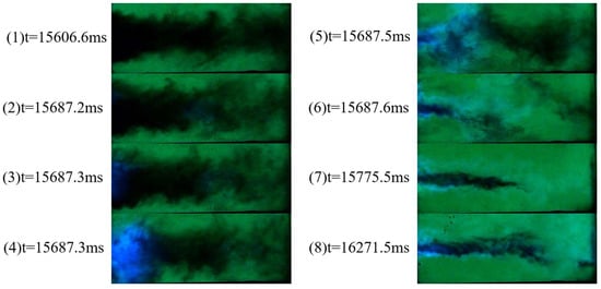
Figure 11.
Ignition flame propagation of shallow recess injector (I-1, D = 5 mm).
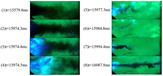
Figure 12.
Ignition flame propagation of deep recess injector (I-2, D = 10 mm).
Subsequently, benefiting from the accelerated pressure build-up rate in the alcohol pipeline, the spray exit velocity stabilizes in advance, effectively avoiding the blow-off interference of the high-speed flow field on the flame. Relying on the uniformly distributed combustible mixture, the flame continuously propagates toward the entire combustion chamber along the flow field, without the occurrence of repeated flame blow-off. Through a brief flame morphology expansion process (Figure 12(5),(6)), the full coverage of the combustion zone is accomplished. Eventually, the time elapsed from jet head ignition to the attainment of quasi-steady combustion (Figure 12(8)) is approximately 113.4 ms, which is much shorter than the combustion stabilization time of the non-recessed injector. At this moment, the flame inside the combustion chamber distributes uniformly, the coupling matching between the spray flow field and the combustion process is optimized, and the system successfully enters a state of sustained and stable combustion.
Observations from time-series images indicate that ignition signals were captured at the head and tail of the jet liquid column at 122.9 ms and 410 ms for the injectors with recess depths of 5 mm and 10 mm, respectively. Compared with the non-recessed I-0 injector, the recessed I-1 and I-2 injectors exhibited distinct characteristics during the ignition process—both followed the pattern of “priority ignition at the jet head”: the flame first ignited the jet head region near the injector exit, then rapidly spread across the entire liquid column centering on the head ignition point. After a brief flame propagation stage, stable ignition was achieved, ultimately forming an axisymmetric combustion flame morphology surrounding the jet liquid column.
The phenomenon of “head priority ignition” in injectors with cavities is mainly due to the fact that the geometric shape of the cavity changes the flow trajectory of the air annular jet and the fragmentation positions of the alcohol and liquid oxygen sprays. The cavity structure changes the velocity gradient distribution at the injector exit, making the liquid oxygen-alcohol mixed jet form a larger recirculation zone in the cavity, which prolongs the residence time of the liquid oxygen and alcohol sprays in the near-field of the injector exit. In addition, through the shear and entrainment effects of the air flow, it promotes the sufficient mixing of fuel and oxidizer in the jet head region, increases the gas–liquid contact area, and makes the liquid oxygen and alcohol more likely to fragment into small droplets. The rapid evaporation characteristics of small droplets enable the jet head region to form a high-concentration combustible vapor cloud in a short time. This characteristic significantly shortens the ignition time and improves the efficiency of the ignition process.
3.4. Quasi-Steady Combustion
After the flame is relayed and stably attached to the injector exit end face, the alcohol jet ignites immediately, and the blue flame surrounds the jet surface, which greatly reduces the amount of alcohol that needs to be entrained into the flammable recirculation zone by air. Some unburned alcohol will be entrained into the recirculation zones on both sides of the combustion chamber injector panel by the main air flow, forming a high-concentration combustible mixture and burning violently, making the recirculation zone present a yellow flame. The combustion intensity, heat release rate, and light intensity are all significantly improved, and the energy output efficiency is increased periodically; after the alcohol in the recirculation zone is burned out, the combustion chamber returns to a stable combustion state, thus forming a periodic process of “stable combustion—alcohol accumulation in the recirculation zone—violent combustion—recovery of stability”. In addition, it can be found that the flame of I-0 presents an arrow-like shape stably attached to the exit end face (Figure 13), while the flames of I-1 (Figure 14) and I-2 (Figure 15) all surround the liquid column and are attached to the injector exit, which is prone to injector ablation.
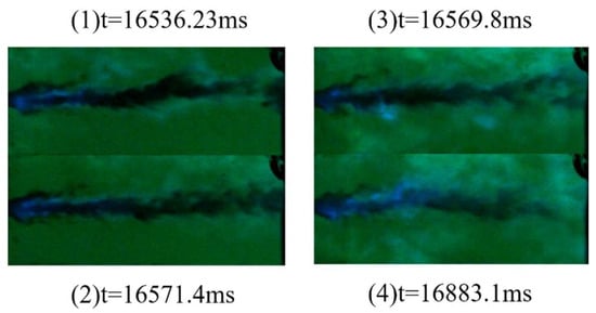
Figure 13.
Quasi-steady and enhanced combustion of non-recessed injector (I-0, D = 0 mm) [34].
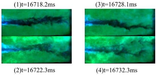
Figure 14.
Quasi-steady and enhanced combustion of shallow recess injector (I-1, D = 5 mm).
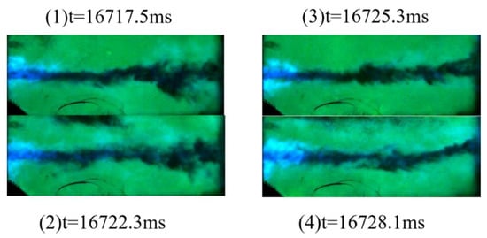
Figure 15.
Quasi-steady and enhanced combustion of deep recess injector (I-2, D = 10 mm).
Combined with the analysis of the chamber pressure curves of the three groups of injectors in Figure 16, it can be seen that all three experience pressure build-up, combustion, and pressure relief stages during the entire combustion period. Focusing on the core combustion period (15~18 s), the pressure oscillation amplitude of the non-recessed P0 is about ±0.2 MPa, the pressure curve of P1 is the smoothest with an oscillation amplitude of only ±0.1 MPa, and the injector P2 with deep recess has the highest pressure peak, exceeding 1.5 MPa, reflecting that the larger the recess amount, the higher the combustion intensity, which is prone to combustion instability. The larger pressure fluctuation amplitude of the recessed injector is mainly due to the fuel accumulation effect of the cavity structure. When the recess amount increases to 10 mm, the cavity space formed at the injector exit significantly enhances the local mixing efficiency of fuel and oxidizer, making the concentration of combustible mixture in the jet head region higher and the energy accumulation more obvious, resulting in violent combustion at the initial stage of ignition and rapid pressure rise. In contrast, the 5 mm recessed cavity space is more moderate, which can not only enhance the combustion intensity through recirculation but also avoid pressure fluctuations caused by excessive fuel accumulation, thus achieving better pressure stability. At the same time, analyzing the relationship between the recess ratio and the ignition time and ignition delay time in Figure 17, it can be seen that the I-1 injector has the shortest ignition time. Comprehensive analysis shows that an appropriate cavity helps to optimize the injector structure design.
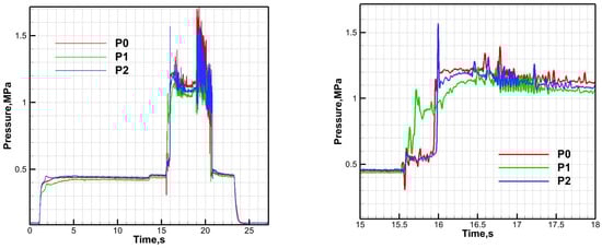
Figure 16.
Chamber pressure curves (left) and local enlarged views (right) of different injectors.
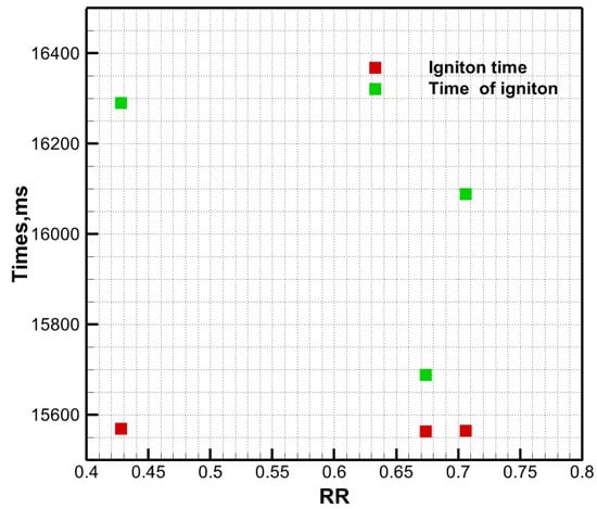
Figure 17.
Relationship between recess ratio and ignition time.
4. Simulation Results and Discussion
4.1. Computational Fluid Domain Model and Boundary Conditions
To precisely investigate the regulation mechanism of injector recess depth on the spray combustion flow field in an air heater, the basic dimensions of the combustion chamber in the computational domain of this study are 368 mm × 141 mm × 45 mm (length × height × width), as illustrated in Figure 18. Local reconstruction is performed based on the core variable of nozzle recess depth, and the geometric structure of the nozzle outlet in the computational domain is adjusted according to three sets of recess depths (D = 0 mm, 5 mm, 10 mm) designed in the experiment. The origin of the coordinate system is set at the center of the alcohol nozzle, with the x-axis pointing to the outlet of the tail nozzle along the axial direction of the combustion chamber, the y-axis along the height direction of the injection panel, and the z-axis along the width direction of the combustion chamber.
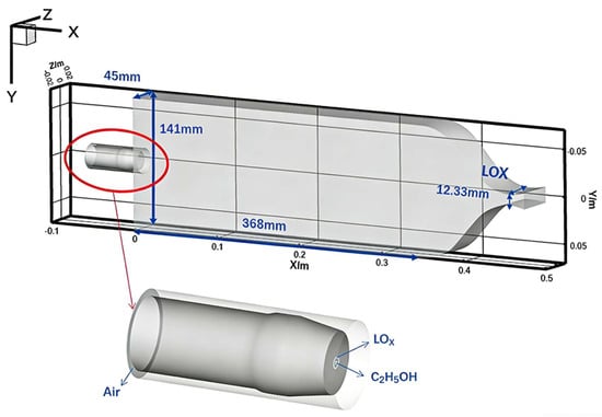
Figure 18.
Computational domain of air heater.
The combustion process in the air heater involves complex physical phenomena such as breakup, atomization and evaporation, gas–liquid mixing, and chemical reactions. The numerical solution adopts a “continuous phase-discrete phase coupling algorithm”: the continuous phase flow is described by the Reynolds-averaged N-S equations, and the standard k-ε model is used for turbulence characteristics; the discrete phase (alcohol and liquid oxygen droplets) uses the DPM model to simulate their motion trajectories and evaporation processes; the eddy-dissipation model (ED) is used for the combustion diffusion process, and the global reaction is adopted for chemical reactions.
4.2. Governing Equations
The framework of the governing equations for the numerical simulation in this study is based on the validated model previously established by the authors for spray combustion in air heaters [34].
In the above equations, t represents physical time, and j represents the coordinate index in the Cartesian coordinate system, where j = 1, 2, 3 correspond to the x, y, and z directions, respectively. Variables ρ, p, T, and Yi represent density, pressure, temperature, and mass fraction of component I, respectively. The component index i ranges from 1 to NSP-1, where NSP is the total number of components. D is the diffusion coefficient. Sdm, Sdu, Sdh, and SdYi represent the mass source term, momentum source term, energy source term, and component source term generated by droplet evaporation, respectively. Slf represents the momentum exchange source term between the continuous phase and the discrete phase. Sch and ScYi correspond to the heat source term and component source term introduced by chemical reactions in the governing equations respectively. Finally, Ru is the universal gas constant, and Mi is the molecular weight of component i.
The turbulence modeling adopts the standard k−ε turbulence model. This model needs to solve the transport equations of turbulent kinetic energy (k) and its dissipation rate (ε). The transport equation of turbulent kinetic energy is strictly derived from the Navier–Stokes equations, while the dissipation rate equation is established based on physical reasoning and mathematical analogy with the prototype equation.
Turbulent Kinetic Energy Transport Equation:
Turbulent Dissipation Rate Equation:
Turbulent Viscosity Coefficient:
In the equations:
4.3. Mesh Generation and Mesh Validation
To ensure computational accuracy, hexahedral structured meshes are used for meshing. The liquid oxygen and alcohol injection surfaces and mixing regions are appropriately refined, as shown in Figure 19, with the number of meshes exceeding 500,000. To examine the influence of mesh resolution on the spray combustion process of the air heater, three sets of meshes are divided, named Mesh 1, 2, and 3 respectively. Each set of meshes has dense grid points arranged at the air annulus, liquid oxygen, alcohol injection surfaces, and reaction mixing layers. The number of meshes for Mesh 1, 2, and 3 is 230,000, 500,000, and 1,010,000, respectively [34].
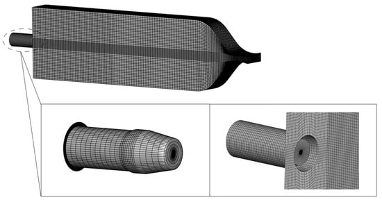
Figure 19.
Mesh schematic diagram (including non-recessed/recessed injector).
According to the thermodynamic calculation (CEA), the total temperature of the gas at the nozzle exit of the air heater is 1551 K. The mass flow-weighted average total temperature at the exit obtained by numerical calculation is shown in Table 3. The relative deviation between the numerical simulation result and the theoretical calculation is within 1%. When the number of meshes reaches 500,000, further mesh refinement has no significant impact on the simulation result (Figure 20), so the mesh with 500,000 meshes is adopted for simulation in this paper [34].
Table 3.
Boundary condition settings.
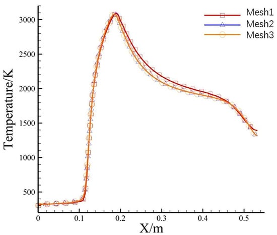
Figure 20.
Quantitative temperature distribution along combustion chamber axis.
4.4. Model Validation
The nozzle exit temperature is an important indicator of the air heater. According to the thermodynamic calculation (CEA), the total temperature of the gas at the nozzle exit of the air heater is 1551 K. The mass flow-weighted average total temperature at the exit obtained by numerical calculation is shown in Table 4. The relative deviation between the numerical simulation result and the theoretical calculation is within 1%, so the simulation model is considered reliable [34].
Table 4.
Mass flow-weighted average temperature of gas at nozzle exit.
4.5. Simulation Result Analysis
In the injection system of the air heater, the cavity structure formed by injector recess plays a key regulatory role in the jet flow field and combustion process. The flow field characteristics of the cavity regulated by the recess amount directly affect the distribution morphology of the combustible mixture and the combustion heat release law, showing obvious differences in macro characteristics such as combustion pressure and flame morphology.
The velocity fields near the injection surfaces of the three sets of injector structures show obvious differences, and their velocity cloud diagrams are shown in Figure 21 and Figure 22. The air jet of the non-recessed injector diffuses directly along the axial direction, the mixing process of fuel and oxidizer depends on the development of the jet itself, and the overall mixing efficiency is low; the recirculation zone of the 5 mm recessed injector is expanded compared with the non-recessed condition, and although the overall velocity field morphology is similar to the non-recessed condition, a local recirculation structure has been formed inside the cavity, and a recirculation vortex appears between the injector panel and the recessed wall surface. The range of the recirculation zone is relatively moderate, which effectively enhances the local mixing effect; the 10 mm recessed injector has a significantly expanded cavity recirculation zone due to the deep cavity design, and the recirculation zones between the injector panel and the upper and lower walls are also obviously enlarged. The deep cavity further strengthens the air flow rotation and velocity gradient, so that the recirculation zone is improved in both spatial range and velocity intensity. The recessed structure can enhance the disturbance effect of the air jet near the injection surface, expand the range of the recirculation zone, and affect the mixing process of fuel and oxidizer. The recessed cavity with recess prolongs the fuel residence time through recirculation, and the larger the recess amount, the more significant the entrainment and mixing effect of the air jet on the fuel, ultimately providing a more sufficient combustible mixture for ignition and combustion.
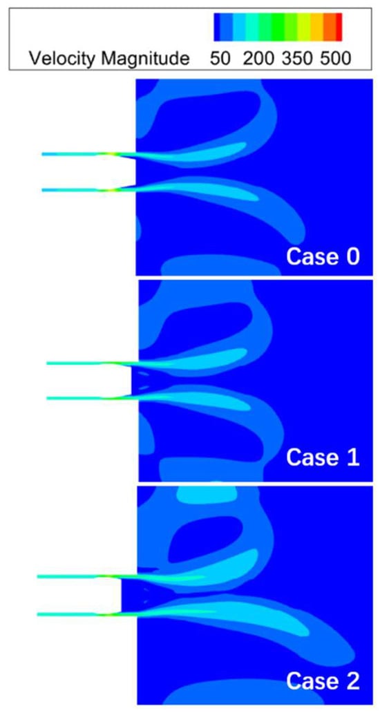
Figure 21.
Velocity cloud diagrams at exits of different injectors.
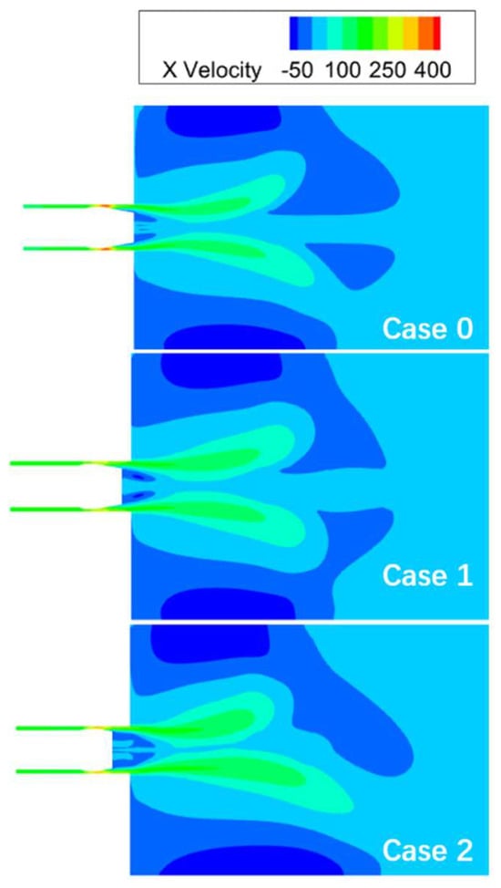
Figure 22.
X-direction velocity cloud diagrams of different injectors.
The liquid oxygen spray atomizes and evaporates into a gaseous state rapidly after entering the combustion chamber. Combined with the liquid oxygen mass fraction cloud Figure 23 and the droplet size distribution Figure 24, it can be seen that the non-recessed liquid oxygen jet penetrates deeply along the axial direction, is concentrated in the upstream region of the combustion chamber, has a limited diffusion range to the wall surface, the shear effect of air on liquid oxygen is weak, the liquid oxygen jet droplets break slowly and have a large particle size, there are only a small amount of small droplets at the gas–liquid interface, and the mixing efficiency with air is low; the penetration depth of the liquid oxygen jet with a shallow cavity is shortened, the radial diffusion range near the injection surface is increased, the mixing region of liquid oxygen and air is wider, the cavity initially restricts the air jet, forms a local disturbed flow field, enhances the entrainment and shear of air on liquid oxygen, makes the liquid oxygen jet droplets break rapidly, the large particle size range is reduced, and the proportion of small droplets is increased; the penetration depth of the liquid oxygen jet with a deep cavity is further reduced, the liquid oxygen presents a large-scale radial diffusion near the injection surface, the concentrated distribution characteristic along the axial direction is significantly weakened, the deep recessed cavity further strengthens the air disturbance, forms a strong recirculation and high velocity gradient flow field, the wrapping and shear effect of air on liquid oxygen is the strongest, and the liquid oxygen completes efficient atomization near the injection surface with the smallest penetration depth and the largest radial diffusion range. The difference in the liquid oxygen flow field distribution caused by the cavity structure essentially changes the momentum exchange efficiency between air and liquid oxygen, thereby regulating the atomization and evaporation process and spatial distribution morphology of liquid oxygen.
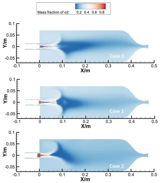
Figure 23.
Liquid oxygen mass fraction distribution diagram.
Figure 24.
Liquid oxygen particle size distribution diagram.
The alcohol jet undergoes unstable fragmentation under the action of air. Combined with the alcohol mass fraction cloud Figure 25 and the droplet size distribution Figure 26, the alcohol jet extends and penetrates along the axial direction, presenting a strip-like concentrated distribution. The particle size at the center of the alcohol jet is the largest, the distance required for alcohol jet atomization is long, and large particle size droplets of 700 μm accumulate at the axis of the combustion chamber, which can only complete uniform atomization at 200 mm away from the injection surface. The injector recess significantly widens the radial diffusion range of the alcohol jet, the mixing region near the injection surface is wider, and the particle size distribution tends to be average at 140 mm away from the injection surface. With the increase of the recess amount, the air disturbance intensity increases, large droplets are more likely to peel off and break under the action of aerodynamic shear, which accelerates the fragmentation and radial diffusion of alcohol droplets. The alcohol jet undergoes violent fragmentation near the injection surface, and the droplets are almost all refined into small droplets, achieving efficient atomization and uniform distribution in the near field.
Figure 25.
Ethanol mass fraction distribution diagram.
Figure 26.
Ethanol particle size distribution diagram.
Combined with the mass fraction distribution curves of different flow direction sections in Figure 27, at the near-injection surface section of X = 0.05 m, the alcohol curve and liquid oxygen curve of Case 0 are both concentrated near the axis, with a narrow and steep shape, indicating weak radial diffusion and a narrow mixing interface. The proportions of carbon dioxide and water curves in this section are low, reflecting weak near-field reaction degree; the alcohol and liquid oxygen curves of Case 1 are slightly widened, the mixing region of alcohol and liquid oxygen is expanded, and the reaction process is advanced compared with Case 0; the distribution range of alcohol and liquid oxygen in Case 2 is also narrow, the overall reaction is limited near the axis, but the reaction starts earlier and is more violent. With the development of the flow direction, it can be clearly seen that at the x = 0.15 m plane, the alcohol of the deep recessed injector has completed atomization, while the alcohol distributions of the non-recessed and shallow recessed injectors are similar, the axis-concentrated “strip” shape does not disappear, but the overall tends to be gentle, and the atomization is relatively uniform according to the reaction products at the central axis at this time. The larger the injector recess amount, the faster the radial mixing uniformity of the components improves.
Figure 27.
Mass fraction distribution curve of the cross-section along the x-axis flow direction.
It can be seen from the temperature cloud diagram that the injector recess amount has a significant influence on the flame structure, mainly reflected in the longitudinal distribution of the flame and the distance between the combustion heat release zone and the injection surface. As shown in Figure 28, from the near-field section to the far-field section, in the near-field section, the high-temperature zone of the non-recessed condition is concentrated near the axis in an annular shape with a narrow radial coverage; the annular structure of the high-temperature zone of the shallow recessed condition is widened, and radial diffusion initially appears; the high-temperature zone of the deep recessed condition presents a wider radial distribution in the near field, and the annular characteristic is weakened. As can be observed from Figure 29 and Figure 30, with the development of the flow direction to the 100 mm and 150 mm sections, the high-temperature zone of the non-recessed condition still maintains the axis-concentrated annular shape, and the radial expansion is slow; the high-temperature zone of the recessed condition with a cavity has transitioned from annular to planar distribution, and the radial coverage range is significantly larger. When the section is 200 mm or farther from the injection surface, the high-temperature zone of the non-recessed condition gradually tends to be uniform at the 400 mm section, while the recessed conditions gradually diffuse to the entire section after the 300 mm and 250 mm sections respectively, completing the thermal field homogenization at the upstream section.
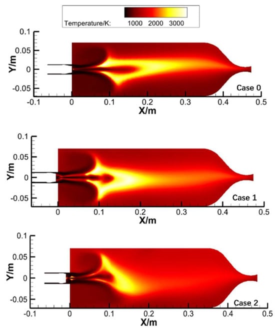
Figure 28.
Symmetrical plane temperature distribution cloud diagram.
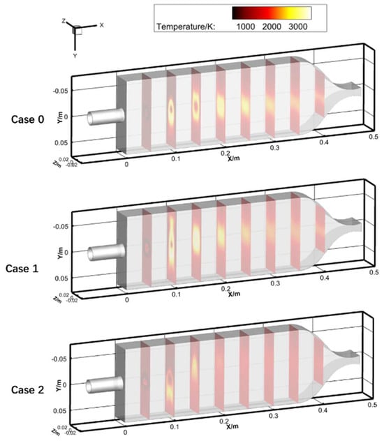
Figure 29.
Flow direction section temperature distribution cloud diagram.
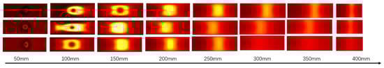
Figure 30.
Temperature distribution cloud diagram along x flow direction section.
With the increase of the recess amount, the air disturbance induced by the cavity is enhanced, which can entrain more hot gas to form a recirculation zone. The flame diffusion effect along the radial direction is obvious, and the average temperature near the injection surface is higher; at the same time, the increase of the recess amount enables the alcohol and liquid oxygen sprays to burn completely in a shorter distance, the combustion heat release zone is significantly advanced, and the flame structure is more compact. Combined with the temperature distribution of different flow direction sections, the combustion heat release zone of the non-recessed injector is concentrated at a relatively far distance from the injector panel, and due to the low atomization and mixing efficiency, the temperature in the combustion chamber is low and unevenly distributed. The unburned components continue to react in the injector, leading to the temperature rise of the injector throat, which affects the quality of the hot gas exit and is not conducive to the thermal protection of the throat. At the same time, the local oxygen content at the injector exit is high, which is easy to form an oxygen-rich combustion zone to ablate the injector, and the flame structure changes little with the increase of the distance from the injection surface. The flame of the shallow recessed injector begins to diffuse in the middle and rear sections of the combustion chamber, the temperature distribution uniformity is improved, and the flame loses its regular shape after 300 mm in the combustion chamber and gradually diffuses to the entire section. The flame of the deep recessed injector diffuses sufficiently at a position closer to the injection surface, has the best mixing and heating effect on air, and the flame structure is compact with sufficient radial coverage, but it will cause the flame to oscillate, lose symmetry, and increase the risk of combustion instability.
The distribution characteristics of CO2 and H2O (Figure 31) clearly reflect the combustion effects of different recess conditions: in the non-recessed condition, the combustion products are closely attached to the center line, the mass fraction peak is low, and there are still residues in the downstream of the combustion chamber, indicating insufficient reaction; the products of the shallow recessed injector are no longer limited to the axis, the radial diffusion range is significantly widened, the generation area near the injection surface is wider, the mass fraction peak is also increased, and the combustion process is advanced; the products of the deep recessed injector achieve a large-scale radial spread in the near-injection surface area, the axis-concentrated phenomenon is greatly weakened, the mass fraction peak reaches the highest, and a high-concentration distribution is formed in the near field. However, it can be found that the flame oscillates and loses symmetry during the combustion process, and the overall combustion stability is poor.
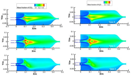
Figure 31.
Cloud diagrams and contour line diagrams of mass fraction distribution of key components in combustion chamber (CO2 on left and H2O on right).
4.6. Comparison Between Experimental and Simulation Results
Referring to the cold spray test of recessed injectors in Feng Junhong’s paper [35], Figure 32 and Figure 33 show the SMD (Sauter Mean Diameter) distribution of three different recess sizes at the Z-section of 210 mm and 290 mm. It can be seen that the recess size affects the distribution of particle SMD. The larger the injector recess size, the smaller the SMD. In the figure, the difference between the injector recess of 0 mm and 4.5 mm is not significant, but the recess of 8 mm significantly reduces the SMD. Combined with the above simulation Figure 24 and Figure 26, it is found that near the injector exit, the particle size of the deep cavity injector is obviously smaller, and with the development of the flow field to the downstream, the particle sizes of other injectors are further refined, which is highly consistent with the trend of the cold test SMD curve. This experimental law is intuitively verified in the simulation droplet size distribution diagram: the droplets of the non-recessed and shallow recessed injectors still maintain a large particle size distribution within a long distance after injection, and gradually refine in the relatively far field region; the droplets of the deep recessed injector complete efficient atomization in the near field region, almost all refined into small droplets.
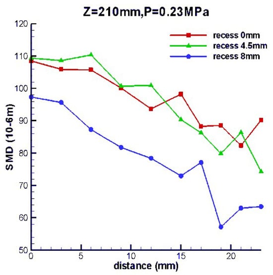
Figure 32.
SMD distribution of different recess sizes in the Z = 210 mm section.
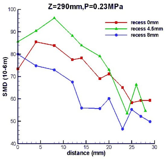
Figure 33.
SMD distribution of different recess sizes in the Z = 290 mm section.
The cold test axial velocity curve shows that the law of “the larger the recess size, the smaller the particle axial velocity” is particularly prominent at the Z = 210 mm (Figure 34) section—the velocity curve of the 8 mm recess condition is significantly lower than that of the 4.5 mm recess and non-recess conditions, and the velocity attenuation is more rapid; while at the Z = 290 mm section(Figure 35), the differences between the velocity curves of the three recess conditions are obviously narrowed and gradually tend to be consistent. This experimental phenomenon can be explained at the mechanism level through the simulation X-direction velocity cloud diagram (Figure 22) in this paper: under the non-recess condition, the air jet is in an axial direct injection shape, the flow field is mainly characterized by direct injection diffusion, the momentum transfer process to the particles is relatively stable, resulting in a slow attenuation rate of the particle axial velocity; the recess forms a local recirculation vortex through the cavity structure, which intensifies the flow field velocity distribution gradient, enhances the momentum dissipation effect of air on the particles, and thus leads to the decrease of the particle axial velocity and the acceleration of the attenuation process; the deep cavity with deep recess further strengthens the air flow rotation effect and velocity gradient, the shear and entrainment effect of air on the particles is the strongest, and finally the particle axial velocity is significantly reduced, and the attenuation rate is the fastest among the three conditions.
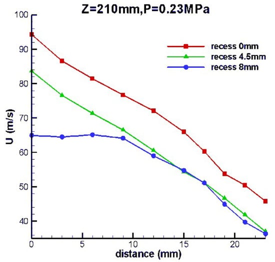
Figure 34.
Particle axial velocity distribution of different recess sizes in the Z = 210 mm section.
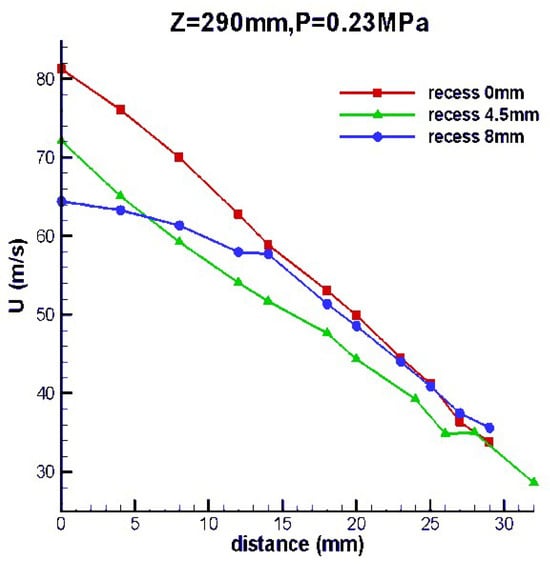
Figure 35.
Particle axial velocity distribution of different recess sizes in the Z = 290 mm section.
Figure 36 shows the comparison between the spray combustion field calculation and experimental results of this paper. From the macro perspective, the flame morphology and combustion zone distribution presented by the simulation are highly consistent with the experimental observations, and the length, width, and overall contour of the flame all show similar characteristics. At the micro level, the distribution of key parameters such as temperature field and component concentration field also have a good matching degree between the simulation results and the experimental analysis. Taking the combustion core region as an example, the numerical value and change trend of temperature, as well as the concentration distribution of main combustion products such as CO2 and H2O, are all mutually confirmed with the experimental results, which fully indicates that the simulation model has high reliability in depicting the characteristics of the spray combustion field.
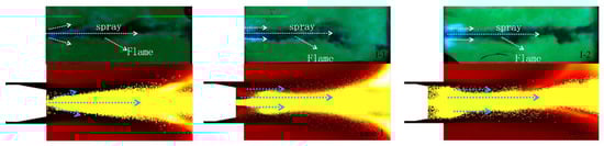
Figure 36.
Comparison between calculated and experimental results of the spray combustion field.
5. Conclusions
This study takes the combustion-type air heater for hypersonic ground tests as the research object, focusing on the key structural parameter of the recess depth of the tripropellant coaxial direct-flow single injector. By building a subscale thermal test system and an optical observation platform, combined with high-speed shadowgraph imaging technology to capture the dynamic processes of ignition, flame propagation, and quasi-steady combustion, and using numerical simulation methods to simulate the flow field velocity, component distribution, and temperature evolution characteristics, the influences of three recess depths (0 mm, 5 mm, 10 mm) on liquid mist diffusion, ignition mode, combustion stability, and flow field regulation mechanism are systematically explored, and the coupling law between recess depth and combustion characteristics is clarified. The main conclusions are summarized as follows:
(1) The injector recess depth has a significant regulatory effect on liquid mist diffusion. With the increase of the recess amount, the radial diffusion range of the liquid mist before ignition expands, but when the recess amount exceeds 5 mm, the improvement of the diffusion effect slows down, showing an obvious “saturation effect”.
(2) The recess structure changes the flame ignition mode. The non-recessed injector adopts the mode of “recirculation zone ignition—jet tail ignition”, while the recessed injector adopts the mode of “jet head priority ignition”. This mode can shorten the ignition response time and improve the efficiency and reliability of ignition start-up under the appropriate recess size.
(3) The recess depth affects combustion stability and intensity. The 5 mm shallow recess condition achieves the smallest chamber pressure fluctuation (±0.1 MPa) with moderate recirculation zone range, which can not only enhance component mixing but also avoid pressure fluctuations caused by excessive fuel accumulation, thus achieving the optimal combustion stability. Although the 10 mm deep recess increases combustion intensity and advances the heat release zone, it will cause flame instability and oscillation, increasing the risk of combustion instability. The non-recessed condition has the lowest atomization and mixing efficiency, uneven combustion temperature distribution, and is prone to secondary reactions at the injector throat.
(4) The numerical simulation results are highly consistent with the experimental results. The recess depth regulates the gas–liquid momentum exchange, droplet fragmentation, and component mixing efficiency by controlling the recirculation characteristics and velocity gradient of the cavity flow field, thereby changing the flame structure and combustion characteristics. Considering combustion stability, mixing efficiency, and ignition performance comprehensively, 5 mm is the optimal injector recess depth for this test system.
Author Contributions
K.W.: Writing and editing; C.S.: Reviewing; B.F.: Experiment. All authors have read and agreed to the published version of the manuscript.
Funding
This research was funded by the National Natural Science Foundation of China (Grant Nos. 11572346 and 12072367) and the Natural Science Foundation of Hunan Province (Grant No. 2020JJ4666); it also received support from the Graduate Student Research and Innovation Program of Hunan Province (Grant No. CX20240130).
Data Availability Statement
The original contributions presented in this study are included in the article. Further inquiries can be directed to the corresponding author.
Conflicts of Interest
The author have no conflicts of interest to declare.
References
- Johnson, A. NASA Glenn Research Center 10-by 10-foot supersonic wind tunnel air heater capability and characterization plans. In Proceedings of the 139th Supersonic Tunnel Association International (STAI) Conference, Albuquerque, NM, USA, 4–6 May 2025; Available online: https://ntrs.nasa.gov/citations/20250003472 (accessed on 15 June 2025).
- Ma, J.D.; Zhang, H.C.; Yu, G.L. Design and experiment of liquid oxygen-alcohol air combustion heater for high-enthalpy wind tunnel. J. Chongqing Univ. Sci. Technol. (Nat. Sci. Ed.) 2025, 27, 107–112. [Google Scholar] [CrossRef]
- Chen, J.F.; Zhang, Q.H.; Tang, Z.G. Performance parameter calculation of regenerative heater in conventional hypersonic wind tunnel. J. Exp. Fluid Mech. 2012, 26, 88–92. [Google Scholar] [CrossRef]
- Samineni, N.B.; Prabu, T.; Yadav, D.R.; Rao, G.A.P. A mathematical framework for design and optimization of regenerative storage heater. Appl. Therm. Eng. 2018, 135, 521–529. [Google Scholar] [CrossRef]
- Sol Baek, J.; Choi, D.; Kim, K.H. Numerical Investigation of Diffusers in Arc-Heated Wind Tunnel: Introducing a Novel and Efficient Hypersonic Diffuser. J. Aerosp. Eng. 2022, 35, 04022070. [Google Scholar] [CrossRef]
- Hashimoto, T. Combustion stability of a vitiated-air heater using coaxial injectors. Combust. Sci. Technol. 1997, 129, 343–360. [Google Scholar] [CrossRef]
- Jiang, Z.; Li, J.; Hu, Z.; Liu, Y.; Yu, H. On theory and methods for advanced detonation-driven hypervelocity shock tunnels. Natl. Sci. Rev. 2020, 7, 1198–1207. [Google Scholar] [CrossRef]
- Jiang, Z.; Hu, Z.M.; Wang, Y.P.; Han, G.L. Advances in critical technologies for hypersonic and high-enthalpy wind tunnel. Chin. J. Aeronaut. 2020, 33, 3027–3038. [Google Scholar] [CrossRef]
- Zhu, J.; Zhang, Y.; Li, Q. Laser ignition characteristics of gaseous oxygen/methane in rocket engine conditions. Acta Astronaut. 2020, 177, 401–412. [Google Scholar] [CrossRef]
- Mayer, W.; Ivancic, B.; Schik, A. Atomization and flame propagation in LOX/GH2 rocket engines. J. Propuls. Power 2015, 31, 783–792. [Google Scholar] [CrossRef]
- Zhang, Y.; Li, J.; Wang, H. Spark ignition energy threshold for LOX/CH4 combustion. Combust. Flame 2019, 205, 1–12. [Google Scholar] [CrossRef]
- Bazarov, V.G.; Yang, V. Liquid-propellant rocket engine injector dynamics. J. Propuls. Power 1998, 14, 797–806. [Google Scholar] [CrossRef]
- Nunome, Y.; Sakamoto, H.; Tamura, H.; Kumakawa, A.; Amagasaki, S.; Inamura, T. An experimental study of super-pulsating flow on a shear coaxial injector with a recessed inner post. In Proceedings of the 43rd AIAA/ASME/SAE/ASEE Joint Propulsion Conference & Exhibit, Cincinnati, OH, USA, 8–11 July 2007; p. 5560. [Google Scholar] [CrossRef]
- Nunome, Y.; Tamura, H.; Onodera, T.; Sakamoto, H.; Kumakawa, A.; Inamura, T. Effect of liquid disintegration on flow instability in a recessed region of a shear coaxial injector. In Proceedings of the 45th AIAA/ASME/SAE/ASEE Joint Propulsion Conference & Exhibit, Denver, CO, USA, 2–5 August 2009; p. 5389. [Google Scholar] [CrossRef]
- Kim, B.D.; Heister, S.D.; Collicott, S.H. Three-dimensional flow simulations in the recessed region of a coaxial injector. J. Propuls. Power 2005, 21, 728–742. [Google Scholar] [CrossRef]
- Kim, B. Study of Hydrodynamic Instability of Shear Coaxial Flow in a Recessed Region (Order No. 3104972). ProQuest Dissertations & Theses Global. 2002. Available online: https://www.proquest.com/dissertations-theses/study-hydrodynamic-instability-shear-coaxial-flow/docview/305493823/se-2 (accessed on 10 April 2023).
- Kawashima, H.; Kobayashi, K.; Tomita, T.; Kaneko, T. A combustion instability phenomenon on a LOX/methane subscale combustor. In Proceedings of the 46th AIAA/ASME/SAE/ASEE Joint Propulsion Conference & Exhibit, Nashville, TN, USA, 25–28 July 2010; p. 7082. [Google Scholar] [CrossRef]
- Staschus, C.; Frederick, R.A. An overview of combustion instabilities and rocket engine injector design. In Proceedings of the 52nd AIAA/SAE/ASEE Joint Propulsion Conference, Salt Lake City, UT, USA, 25–27 July 2016; p. 4724. [Google Scholar] [CrossRef]
- Gröning, S.; Hardi, J.S.; Suslov, D.; Oschwald, M. Injector-driven combustion instabilities in a hydrogen/oxygen rocket combustor. J. Propuls. Power 2016, 32, 560–573. [Google Scholar] [CrossRef]
- Canino, J.; Heister, S.; Sankaran, V.; Zakharov, S. Unsteady response of recessed-post coaxial injectors. In Proceedings of the 41st AIAA/ASME/SAE/ASEE Joint Propulsion Conference & Exhibit, Tucson, AZ, USA, 10–13 July 2005; p. 4297. [Google Scholar] [CrossRef]
- Matsuyama, S.; Shinjo, J.; Ogawa, S.; Mizobuchi, Y. Large eddy simulation of high-frequency combustion instability of supercritical LOX/GH2 flame. In Proceedings of the 46th AIAA/ASME/SAE/ASEE Joint Propulsion Conference & Exhibit, Nashville, TN, USA, 25–28 July 2010; p. 6567. [Google Scholar] [CrossRef]
- Tsohas, J.; Heister, S.D. Numerical simulations of liquid rocket coaxial injector hydrodynamics. J. Propuls. Power 2011, 27, 793–810. [Google Scholar] [CrossRef]
- Tsohas, J.; Canino, J.; Heister, S. Computational modelling of rocket injector internal flows. In Proceedings of the 43rd AIAA/ASME/SAE/ASEE Joint Propulsion Conference & Exhibit, Cincinnati, OH, USA, 8–11 July 2007; p. 5571. [Google Scholar] [CrossRef]
- Tsohas, J.; Heister, S. CFD simulations of liquid rocket coaxial injector hydrodynamics. In Proceedings of the 45th AIAA/ASME/SAE/ASEE Joint Propulsion Conference & Exhibit, Denver, CO, USA, 2–5 August 2009; p. 5387. [Google Scholar] [CrossRef]
- Tsohas, J. Hydrodynamics of Shear Coaxial Liquid Rocket Injectors (Order No. 3379776). ProQuest Dissertations & Theses Global. 2009. Available online: https://www.proquest.com/dissertations-theses/hydrodynamics-shear-coaxial-liquid-rocket/docview/304989425/se-2 (accessed on 8 May 2022).
- Yu, Y.C.; Sisco, J.C.; Rosen, S.; Madhav, A.; Anderson, W.E. Spontaneous longitudinal combustion instability in a continuously-variable resonance combustor. J. Propuls. Power 2012, 28, 876–887. [Google Scholar] [CrossRef]
- Smith, R.; Xia, G.; Anderson, W.A.; Merkle, C.L. Computational simulations of the effect of backstep height on nonpremixed combustion instability. AIAA J. 2010, 48, 1857–1868. [Google Scholar] [CrossRef]
- Ding, Z.B.; Tao, R.F.; Xu, X.Y. Effect of structure parameters of GH2/LOX shear coaxial injector on combustion characteristics. J. Rocket Propuls. 2013, 35, 31–34. [Google Scholar] [CrossRef]
- Sun, J.G.; Zhuang, F.C.; Wang, J. Effects of recess on coaxial injector’s discharge coefficient and performance. J. Propuls. Technol. 2003, 24, 452–455. [Google Scholar] [CrossRef]
- Wang, D.; Nie, W.S.; Zhou, S.Y.; Wang, H.Q.; Su, L.Y. Experimental analysis on the longitudinal high-frequency combustion instability of a single-element model engine. J. Exp. Fluid Mech. 2018, 32, 18–23, 73. [Google Scholar] [CrossRef]
- Wang, Z.; Hu, J.H.; Yang, J.W.; Jin, D.; Li, Y.D.; Huo, S.H. Effects of structural parameters of gas-gas coaxial straight-flow injector on combustion performance. J. Rocket Propuls. 2022, 48, 32–39. [Google Scholar] [CrossRef]
- Yang, L.J.; Ge, M.H.; Zhang, M.Z.; Fu, Q.F.; Cai, G.B. Spray characteristics of recessed gas-liquid coaxial swirl injector. J. Propuls. Power 2008, 24, 1332–1339. [Google Scholar] [CrossRef]
- Li, Q.; Kang, Z.; Zhang, X.; Cheng, P. Effect of recess length on the spray characteristics of liquid-centered swirl coaxial injectors. At. Sprays 2016, 26, 535–550. [Google Scholar] [CrossRef]
- Wang, K.; Shen, C.B.; Fan, B. Annular air gap area impact on flame regime transition and combustion in low-chamber-pressure air heater. J. Appl. Fluid Mech. 2026, 19, 3202–3220. [Google Scholar] [CrossRef]
- Feng, J.H. Numerical Simulation and Experimental Study of High-Enthalpy and High-Pressure Air Heater. Master’s Thesis, National University of Defense Technology, Changsha, China, 2011. [Google Scholar]


Disclaimer/Publisher’s Note: The statements, opinions and data contained in all publications are solely those of the individual author(s) and contributor(s) and not of MDPI and/or the editor(s). MDPI and/or the editor(s) disclaim responsibility for any injury to people or property resulting from any ideas, methods, instructions or products referred to in the content. |
© 2025 by the authors. Licensee MDPI, Basel, Switzerland. This article is an open access article distributed under the terms and conditions of the Creative Commons Attribution (CC BY) license.