Abstract
Solar sailing has proven to be an effective solution for cost-effective and long-term space missions due to its fuel-free propulsion. While multiple large-scale solar sails based on kilogram-class satellites have been developed and tested in space, solar sails created for lightweight chip-scale satellites are much less. To enable the gram-class satellite of solar sailing for active attitude adjustment and orbital maneuvers, a novel solar sail driven by two-way shape memory effect (TWSME) was proposed in this work. The solar sail base was made of rectangular Al-Kapton thin films, while a U-shaped NiTi beam was developed by 50 μm thin Ni50.6Ti49.4 foils. Both of the U-shaped NiTi beam and rectangular Al-Kapton thin films were manufactured by the ultra-fast femtosecond laser cutting machine. Finite element modeling of single U-shaped NiTi beam and assembled solar sail were built to validate that an 80 mm-long TWSME NiTi beam with a curvature of 37.31 m−1 were sufficient to drive the solar sail for solar radiation pressure modulation. A solar sail prototype was developed, and an in situ experiment test of the prototype was conducted with infrared imaging, showing efficient bending behaviors by application of a 0.5 A direct current across the U-shape NiTi beam. These findings reveal that U-shaped TWSME NiTi foils provide an effective driving strategy for lightweight chip-scale satellites, and thus dramatically broaden the space application of the gram-scale satellite.
1. Introduction
Over the past two decades, significant advancements have been achieved in the development of solar sail spacecraft for space exploration [1]. Solar sails exploit solar radiation pressure exerted by the Sun during orbital flight, enabling long-duration and cost-effective missions through a small yet continuous propulsive force [2]. Compared with conventional propulsion systems—which rely on limited onboard propellants and bulky mechanical components—solar sailing offers substantial mass reduction and extended satellite lifespan [3]. However, past demonstrations involving kilogram-class CubeSats have revealed a critical limitation: achieving high area-to-mass ratio configurations capable of actively modulating solar radiation pressure remains challenging, thereby hindering broader and more practical applications [4].
Research on modulating solar radiation pressure for attitude control began as early as 1973 [5]. Due to technical constraints in deploying large-area sails on traditionally heavy spacecraft, the first laboratory-based deployment experiment was conducted under the DLR-ESA-funded Odyssee project in 2003 [6]. In 2005, the Planetary Society’s Cosmos-1 became the first solar sail spacecraft launched into space, designed to deploy a 600 m2 sail and modulate radiation pressure using eight inflatable tube-driven blades [7]. Although the design achieved an area-to-mass ratio of 6.0 m2/kg, the spacecraft failed to detach from the Volna launch vehicle and was lost in a launch failure.
In 2010, Japan’s IKAROS, developed by JAXA, achieved the first successful solar sail deployment in space using spin-induced deployment and demonstrated solar radiation pressure modulation via variable-reflectivity liquid crystal panels [8,9]. However, its area-to-mass ratio was only 0.61 m2/kg, limiting its propulsion efficiency and possibly contributing to its inability to reach Venusian orbit. Subsequent missions such as NASA’s NanoSail-D2, launched after the failed 2008 NanoSail-D, deployed a 10 m2 aluminum-coated Mylar sail via triangular, rollable, and collapsible (TRAC) booms [10,11]. Although the system achieved an area-to-mass ratio of 2.5 m2/kg, atmospheric drag overshadowed the effect of solar radiation pressure, and the sail geometry remained fixed post-deployment, precluding active modulation. The LightSail 1 and LightSail 2 missions (launched in 2015 and 2019, respectively) further demonstrated solar sailing feasibility for orbital maneuvers [12,13]. Both achieved an area-to-mass ratio of ~6.35 m2/kg. However, sail geometry was kept planar, and attitude control relied on internal momentum wheels and torque rods within the 3U CubeSat. In 2022, NASA’s Near-Earth Asteroid Scout (NEA Scout) successfully deployed an 84.6 m2 sail via four 7.3 m TRAC booms from a 6U CubeSat (mass: 11.629 kg), achieving an area-to-mass ratio of 7.27 m2/kg [14,15]. The flat sail employed a center-of-mass shifting actuator for attitude control. However, the spacecraft never established communication, and no flight data were retrieved. In 2024, NASA successfully deployed the Advanced Composite Solar Sail System (ACS3) from a 12U CubeSat (mass: 16 kg) using four composite booms and an ~80 m2 sail [16]. Despite successful deployment, the spacecraft has been tumbling at ~1000 km altitude, impairing high-bandwidth communication due to imprecise antenna pointing. Like NEA Scout, ACS3 used an active mass translator for attitude control, achieving an area-to-mass ratio of 5.0 m2/kg.
Despite these advances, several persistent challenges—such as the bending stiffness of support booms and heavy dependence on a centralized spacecraft platform—limit the applicability of traditional solar sail designs [17]. Recent research into smart materials, particularly shape memory alloys (SMAs), has shown great promise for enabling more lightweight, compact, and actively controllable solar sails [18,19,20,21,22,23,24]. For example, Costanza’s group developed small-scale prototypes incorporating Al-Kapton-based sails actuated by NiTi wires. These systems, while demonstrating self-deployment capabilities, relied on external infrared heating and offered limited geometric control [21,22]. They further introduced a design using SMA foil embedded in a carbon fiber loom to achieve cylindrical bending in 20 × 20 cm sails [23]. Similarly, Karmakar’s group employed an SMA-actuated guide rod to deploy an aluminum foil sail via Joule heating, achieving a 90° bend [24]. However, such systems are often bulky and mechanically complex, making them unsuitable for high area-to-mass ratio applications.
Building upon our prior work involving shape memory effect, thermal mismatch actuation, and distributed control strategies [25,26,27,28,29,30,31,32,33], we propose a novel solar sail design utilizing ultra-thin NiTi SMA foils treated for TWSME. These foils are precisely patterned into U-shaped actuators using femtosecond laser machining. By regulating power input to the SMA actuators, continuous and reversible geometry transformations can be achieved, enabling real-time modulation of solar radiation pressure. The research scheme proposed in this study overcomes the limitations of micro-scale conceptual designs, enabling controllable deployment and engineering application based on the shape memory effect, thereby paving the way for the transition of the system from experimental exploration to practical space missions.
The article is organized as follows. Structural design and morphing principle of solar sails driven by TWSME NiTi actuators are illustrated in Section 2, followed by thermo-mechanical simulation and evaluation of their reconfigurable behaviors in Section 3. Section 4 discusses the results and limitations, and Section 5 concludes this research.
2. Structural Design and Morphing Principle
To enable effective modulation of solar radiation pressure, this section proposes a novel solar sail architecture based on Al-Kapton composite films actuated by U-shaped NiTi elements exhibiting the TWSME. The conceptual design adopts an X-shaped configuration composed of four independently controlled rectangular sail segments, as illustrated in Figure 1.
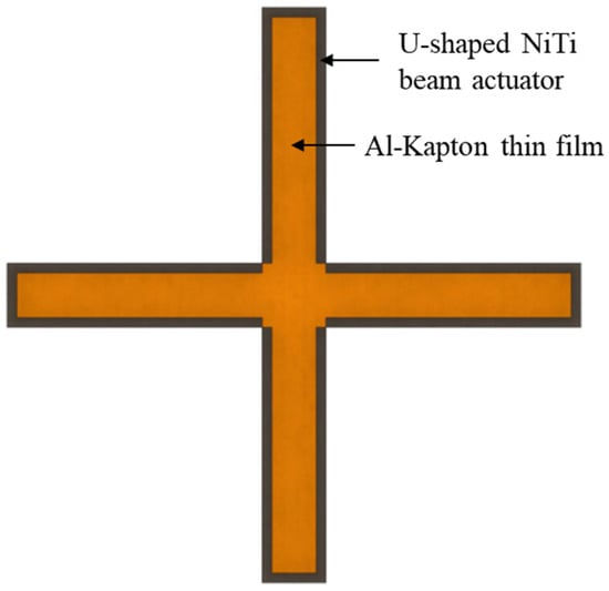
Figure 1.
Structural design of TWSMA driven solar sail.
In the design, each rectangular Al-Kapton substrate is designed to be the same size as the assembled U-shaped NiTi beam actuator. The actuator is affixed to the Al-Kapton film using an ultra-thin, double-sided adhesive layer, ensuring minimal interference with the sail’s mechanical properties. Specifically, a high-adhesion double-sided pressure-sensitive adhesive was employed to achieve a tight, gap-free bond between the Al-Kapton substrate and the U-shaped NiTi beam. Each sail segment can be independently actuated by its respective NiTi beam, allowing for real-time, adaptive reconfiguration of the overall X-shaped sail geometry. This modular actuation strategy facilitates active modulation of solar radiation pressure. The bending behavior of a single sail segment is shown in Figure 2.
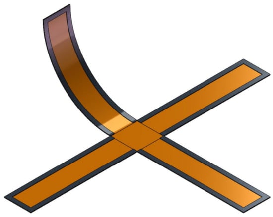
Figure 2.
Bending of different solar sails for modulation of solar radiation pressure.
The NiTi thin foils employed in this study have a near-equiatomic composition (Ni50.6Ti49.4) and are thermally processed—specifically annealed and aged—to exhibit stable TWSME characteristics. The transformation behavior is defined by four critical temperatures: the austenite start (As) and finish (Af) temperatures, and the R-phase start (Rs) and finish (Rf) temperatures. At temperatures below Rs, the NiTi foils remain in a flat configuration, governed by the initial solution treatment. Upon heating beyond Af, the foils undergo a reversible transformation into a curved shape, preprogrammed through constrained aging. U-shaped actuators are precisely fabricated from the treated foils using femtosecond laser micromachining.
These U-shaped NiTi actuators are electrically conductive and can be thermally actuated via direct Joule heating. In their initial state, the composite sail structure is flat, with the NiTi beams in the R-phase at ambient temperatures below Rs. When a direct current is applied, resistive heating elevates the beam temperature, and the final steady-state temperature is primarily determined by the magnitude of the current. As the temperature transitions between Rf and Af, the NiTi actuator morphs from a flat to a curved shape, inducing a corresponding deformation in the attached Al-Kapton sail. Each sail segment can therefore be independently controlled by modulating the current applied to its respective actuator. This enables dynamic, continuous shape reconfiguration of the X-shaped solar sail, with geometric transformations ranging from fully planar to significantly curved states, as depicted in Figure 3.
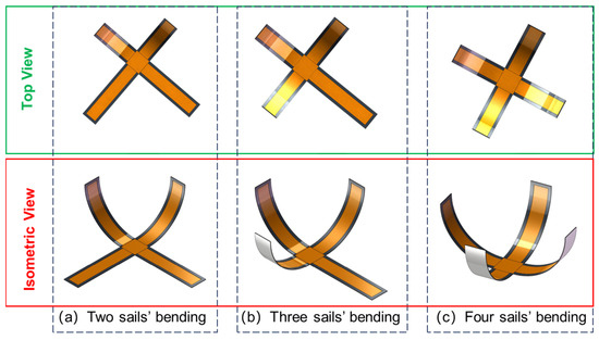
Figure 3.
Typical reconfigurable geometries of X-shaped solar sails driven by four independent U-shaped TWSMA NiTi beams.
3. Fabrication, Simulation and Experiment
3.1. TWSME Training Procedure and Laser Cutting of NiTi Thin Film
The NiTi alloy used in this study was commercially sourced with a nominal atomic ratio of 1:1. Since the atomic ratio plays a decisive role in determining phase transformation temperatures, energy-dispersive X-ray spectroscopy (EDS) was performed to verify the actual composition of the material, as shown in Figure 4. Elemental analysis of multiple regions on the sample surface revealed an atomic ratio of 50.9:49.1.
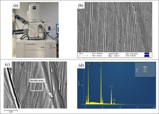
Figure 4.
ZEISS Field Emission Scanning Electron Microscope (Carl Zeiss AG, Germany) (a) surface topography imaging (b) sample area (c) for atomic ratio characterization (d) of NiTi alloy for TWSME training.
In this study, a multi-step thermal training procedure was applied to 50 μm-thick Ni50.6Ti49.4 shape memory alloy foils to induce a stable TWSME. The process included three sequential treatments: solution treatment, constraint aging treatment, and load-free aging treatment. Specifically, solution treatment was conducted at 850 °C for 4 h in a vacuum environment under argon protection. This was followed by constraint aging treatment at 450 °C for 3 h using a semi-circular mold in a muffle furnace. Finally, the foils underwent load-free aging treatment at 400 °C for 4 h. Differential scanning calorimetry (DSC) analysis was conducted post-treatment to determine key phase transformation temperatures, as shown in Figure 5. The results indicate an R-phase finish temperature of approximately 30 °C and an austenite finish temperature of about 55 °C.
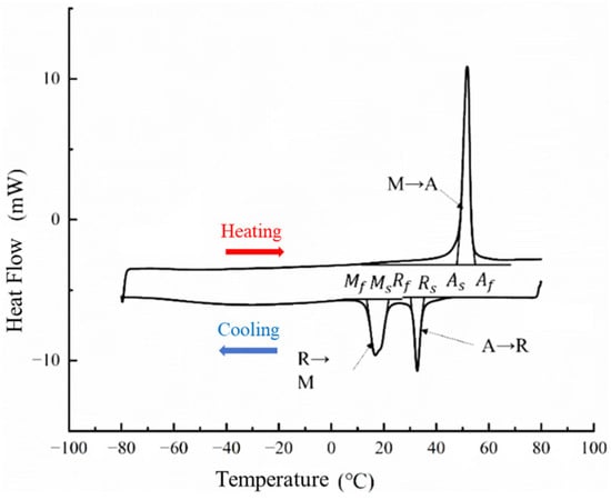
Figure 5.
Characterization of transformation temperature of TWSMA NiTi thin foil after shape memory effect treatments. (Mf: Martensite finish temperature Ms: Martensite start temperature Af: Austenite finish temperature As: Austenite start temperature Rf: R-phase finish temperature Rs: R-phase start temperature).
Following thermal treatment, the foils were precisely patterned into U-shaped actuators using a femtosecond laser micromachining system. These actuators were then integrated with laser-cut rectangular Al-Kapton films using an ultra-thin double-sided adhesive layer to fabricate TWSME-driven solar sail units. The structural layout of a representative actuator–sail assembly is depicted in Figure 6, and the associated material and geometric properties are summarized in Table 1.
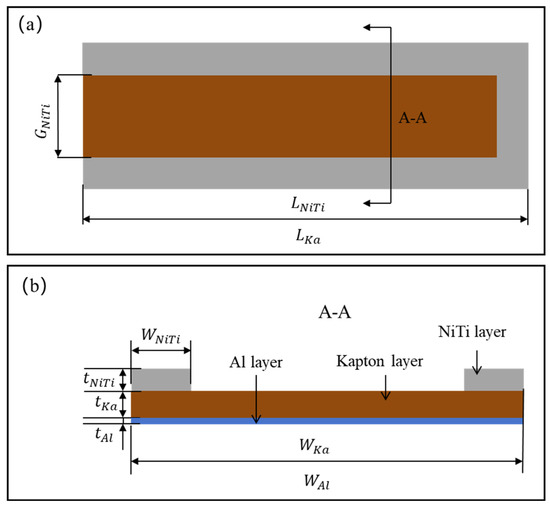
Figure 6.
Structural parameters of a rectangular Al-Kapton sail driven by a U shaped NiTi actuator, top view (a) and cross section A-A (b).

Table 1.
Structural and material parameters of the rectangular Al-Kapton sail.
Moreover, tensile testing of the NiTi actuator at a temperature range from the R-phase finish temperature to the austenite finish temperature revealed an average Young’s moduli of 31.3 GPa. Four-point measurement of resistance of the NiTi foil at the same temperature range was conducted (as seen in Figure 7). As a result, the resistance of the TWSMA NiTi actuator at the austenite finish temperature of 55 °C was acquired as 0.0032 Ω⋅mm.
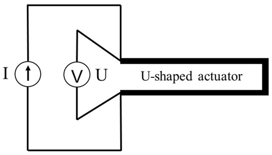
Figure 7.
Four-point measurement of resistance of the NiTi foil at different balanced temperatures by current DC source Joule heating.
3.2. Finite Element Modeling and Simulation
The solar radiation pressure modulation ability of proposed rectangular solar sail can be dominated by its reconfigurability driven by TWSME NiTi actuators. The thermally driven solar sail needs to be evaluated through thermo-mechanical modeling for determination of proper structural parameters. In this work, a 50 μm thick NiTi foil was processed by an iron TWSME treatment mold with a curvature of 39.27 m−1, or radius of curvature of 25.5 mm, as seen in Figure 8a. The U-shaped NiTi actuator with TWSME after laser cutting is shown in Figure 8b, which was bonded onto the laser cut Al-Kapton film through double sided adhesive tape. Key parameters used in this simulation are listed in Table 2, where it is worth emphasizing that the TWSME of the NiTi beam actuator was mathematically equivalent to a negative coefficient of thermal expansion, −1 × 10⁻⁴ K−1.
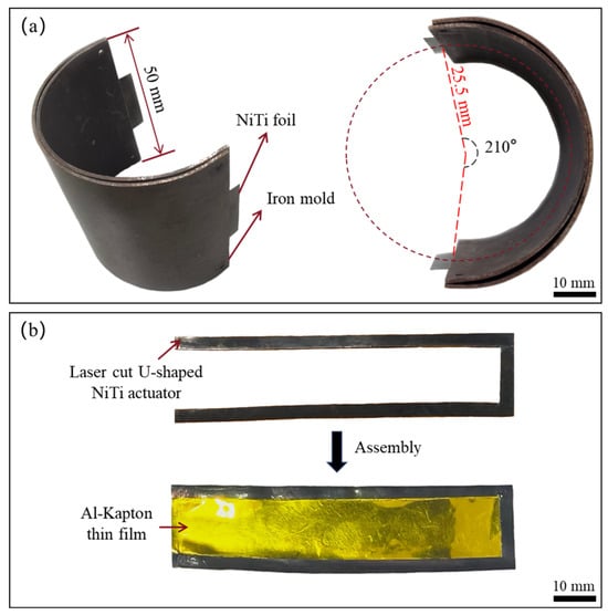
Figure 8.
The iron mold for TWSME treatment of the NiTi foil (a) and the U-shaped NiTi actuator cut by the ultra-fast femtosecond laser cutting machine (b).
Table 2.
Key parameters for thermo-mechanical modeling of the solar sail.
A finite element model was established with structural parameters of
= 0.001 mm,
= 0.024 mm,
= 0.05 mm,
= 20 mm,
= 80 mm,
= 3 mm,
= 80 mm and
= 14 mm. The model was meshed by the thermal-coupled element with dimensions of 40 μm, and the left side of the solar sail was fixed while the right was set free, as seen in Figure 9.
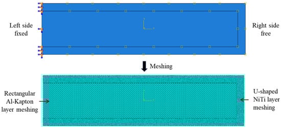
Figure 9.
Finite element model of the solar sail with boundary conditions (top) and meshing (bottom).
To ensure full actuation, the Joule heating must raise the NiTi actuator temperature above its austenite finish temperature (55 °C). Given the ambient temperature of 25 °C, direct currents ranging from 0.1 A to 0.6 A were applied during simulation. The results indicated that a current of 0.5 A was sufficient to elevate the NiTi beam’s temperature beyond the austenite finish temperature, even in the presence of thermal dissipation into the Al-Kapton film.
FE simulation outcomes are shown in Figure 10. For the isolated NiTi beam (Figure 10a), the actuator morphed into an arc with a bending angle of approximately 171°, corresponding to a curvature of 37.31 m−1. This value was slightly lower than that of the training mold, likely due to partial degradation of the TWSME during laser cutting. When bonded to the Al-Kapton film (Figure 10b), the actuator-induced bending was reduced to ~103°, corresponding to a curvature of 22.47 m−1. This reduction is attributed to the Al-Kapton film functioning as a passive structural constraint. According to the requirements of solar radiation pressure modulation, such a bending angle satisfies effective reconfiguration of the solar sail from the geometry shown in Figure 1 to that shown in Figure 2.
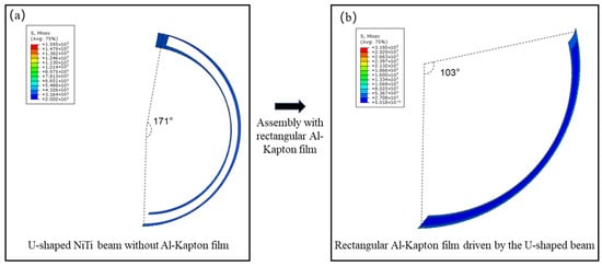
Figure 10.
Finite element results of thermo-mechanical models of the U-shaped TWSME NiTi beam with (a) without (b) the rectangular Al-Kapton film.
3.3. Experimental Validation
To experimentally validate the thermo-mechanical modeling and material behavior, a prototype solar sail was assembled using a U-shaped TWSME NiTi actuator (raw material bought from Baoji Runyang Rare Metals Co., Ltd., Shaanxi Province, China) and a rectangular Al-Kapton film (raw material bought from Kunshan Borfa New Material Technology Co., Ltd., Jiangsu Province, China), as shown in Figure 11.
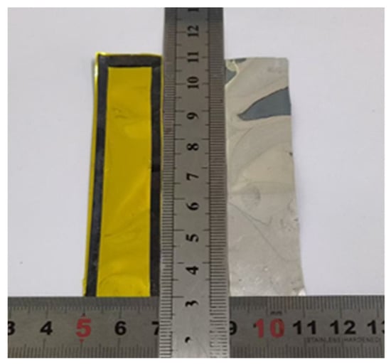
Figure 11.
A solar sail prototype created via assembly of a U-shaped TWSME NiTi actuator and rectangular Al-Kapton film.
A custom-built current regulation circuit, mounted on a printed circuit board (PCB), was employed to control the applied current from the DC power source. When a current of 0.5 A was supplied to the actuator, the steady-state temperature exceeded the austenite finish temperature. The experimental setup for in situ measurement of the solar sail prototype for three-dimensional is seen in Figure 12.
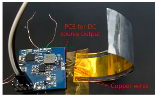
Figure 12.
Three-dimensional reconfiguration of a TWSME driven solar sail prototype when a 0.5 A current was applied by a DC source.
To comprehensively show the electro-thermal driving process, a FLIR A655sc infrared imaging instrument was employed for characterization of the reconfiguration process. Originally, the solar sail was flat without any power, and the temperature across the sail was measured to be around 25 °C, as seen in Figure 13a. Then, out-of-plane morphing occurred once a current of 0.5 A was applied, and the balanced temperature on the solar sail was up to 81 °C. The bending angle of the 80 mm long solar sail prototype was measured to be 108°, or a curvature of 23.56 m−1, which proves a good agreement with the finite element results (22.47 m−1). Infrared imaging of the electro-thermal actuation process of the solar sail is shown in Supplementary Video S1, which demonstrates the reconfigurable capability of developed solar sails.
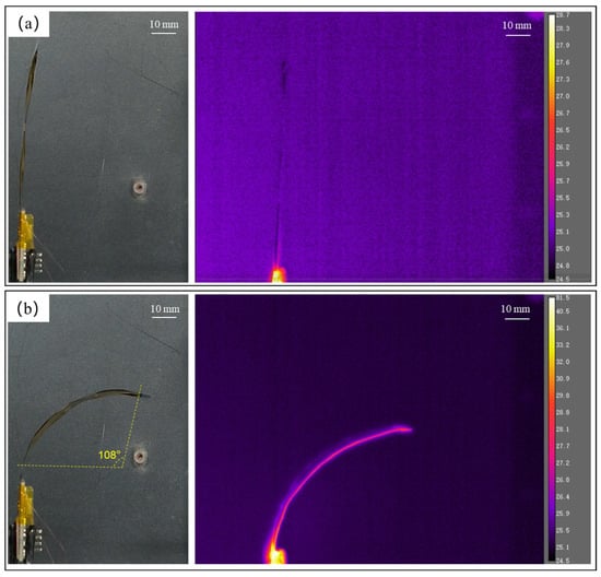
Figure 13.
Infrared imaging of the initial geometry (a) and final reconfiguration (b) of the solar sail prototype under Joule heating.
4. Discussion
This work presents a novel solar sail actuated by U-shaped NiTi beams with TWSME. The solar sail incorporates a laser-cut Al-Kapton film as the reflective surface, actuated by accurately fabricated U-shaped NiTi elements. Both the Al-Kapton and NiTi components were processed using an ultra-fast femtosecond laser cutting system to ensure dimensional accuracy and reproducibility. Raw Ni50.6Ti49.4 foils, 50 μm thick, were thermally treated on a fixed-curvature iron mold (39.27 m−1) to realize the TWSME. However, post-fabrication measurements revealed a slightly lower resulting curvature of 37.31 m−1. This deviation is attributed to local thermal effects introduced during femtosecond laser cutting, which may partially alter the phase transformation behavior of the trained NiTi foil. Future work will explore the influence of laser processing parameters on the TWSME performance in greater detail. Beyond that, although in situ characterization of the reconfigurable behavior of the solar sail prototype was clearly monitored by the infrared imaging video in air, experimental setup for the solar sail in vacuum surroundings could be more meaningful. Moreover, given the significant influence of the thermal convection on the balanced temperature of the U-shaped NiTi beam in air, much less power, or smaller current, would be demanded for achieving the same temperature beyond the austenite finish temperature.
5. Conclusions
In conclusion, the assembly of the TWSME NiTi beam with the Al-Kapton film has proven a feasible solution in the active control of the geometry of the solar sail for solar radiation modulation. The TWSME NiTi beam can be developed via thermal treatment and an ultra-fast femtosecond laser cutting machine using ultra-thin raw Ni50.6Ti49.4 foils, while the off-the-shelf Al-Kapton film can be customized accordingly by laser cutting. Finite element models of a typical geometry of the solar sail were built for validation of the driving effect of the U-shaped NiTi beam on the passive Al-Kapton film. Besides that, characterization and experimental testing of the solar sail prototype successfully prove that efficient out-of-plane deformation of the original flat geometry was achieved by a direct current of 0.5 A, and the deformed curvature was measured to be 23.56 m−1, which revealed a high consistency with that acquired by the finite element model. Therefore, we envision promising applications of the novel solar sail in developing a lightweight space system for solar sailing. In the future, more structural designs and physical experiments of such solar sails will be studied. Beyond that, chip-scale satellites with the required driving functions will also be developed for efficient active control of proposed solar sails.
Supplementary Materials
The following supporting information can be downloaded at https://www.mdpi.com/article/10.3390/aerospace13010014/s1: Video S1: Infrared imaging of the electro-thermal actuation process of the solar sail.
Author Contributions
Conceptualization, Z.R. and C.L.; methodology, R.C. and P.J.; software, P.J. and C.L.; validation, R.C., Z.R., Z.T. and B.J.; formal analysis, Z.R., X.Z. and Z.W.; investigation, Z.R. and P.J.; resources, R.C., Z.R., D.L. and E.L.; data curation, R.C., P.J. and C.L.; writing—original draft preparation Z.R., P.J. and C.L.; writing—review and editing, Z.R., D.L. and Z.W.; visualization P.J.; supervision, Z.R.; project administration, Z.R. and E.L.; funding acquisition, Z.R., R.C. and Z.W. All authors have read and agreed to the published version of the manuscript.
Funding
This research was funded by Excellent Youth Science Fund Project (Overseas) of Shandong Province, China, (Grant No. 2023HWYQ-029), China Postdoctoral Science Foundation, (Grant No. 2023MD744219), Zhejiang Province Selected Funding for Postdoctoral Research Projects (Grant No. ZJ2023040), Gansu Province Postdoctoral Fund (Grant No. 24JRRA219), Youth Project of Natural Science Foundation of Shandong Province, China (Grant No. ZR2023QE127; ZR2023QE187), Guangdong Basic and Applied Basic Research Foundation (Grant No. 2023A1515110509), Zhejiang Key Research and Development Plan of China (Grant No. 72022001099; 2024001219), National Natural Science Foundation of China (Grant No. 52305606), Taishan Scholars Project of Shandong Province (Grant No. tsqn202306028), Basic Research Program of Jiangsu (Grant No. BK20230254), and Key Laboratory of High-efficiency and Clean Mechanical Manufacture at Shandong University, Ministry of Education.
Data Availability Statement
The raw data supporting the conclusions of this article will be made available by the authors on request.
Conflicts of Interest
Authors Ruilei Chen and Zhongjing Ren were employed by the company Zhejiang Julihuang Sawing Machine Group Co., Ltd. The remaining authors declare that the research was conducted in the absence of any commercial or financial relationships that could be construed as a potential conflict of interest.
References
- Thompson, S.M.; Pushparaj, N.; Cappelletti, C. Reflective and transmissive solar sails: Dynamics, flight regimes and applications. Acta Astronaut. 2024, 220, 478–494. [Google Scholar] [CrossRef]
- Liu, T.W.; Bai, J.B.; Fantuzzi, N.; Zhang, X. Thin-walled deployable composite structures: A review. Prog. Aerosp. Sci. 2024, 146, 100985. [Google Scholar] [CrossRef]
- Bae, J.; Kang, J. Design concepts and control algorithm to minimize the control effort for earth-orbit-raising solar sails. Aerosp. Sci. Technol. 2024, 146, 108994. [Google Scholar] [CrossRef]
- Zhao, P.; Wu, C.; Li, Y. Design and application of solar sailing: A review on key technologies. Chin. J. Aeronaut. 2023, 36, 125–144. [Google Scholar] [CrossRef]
- Grinevitskaya, L.K.; Polyakhova, E.N. Approximate solution of the equations of geocentric motion of a space vehicle with a solar sail. Leningr. Univ. Bull. Math. Mech. Astron. 1973, 7, 134–143. [Google Scholar]
- Leipold, M.; Eiden, M.; Garner, C.E.; Herbeck, L.; Kassing, D.; Niederstadt, T.; Krüger, T.; Pagel, G.; Rezazad, M.; Rozemeijer, H.; et al. Solar sail technology development and demonstration. Acta Astronaut. 2003, 52, 317–326. [Google Scholar] [CrossRef]
- Reichhardt, T. Setting sail for history. Nature 2005, 433, 678–679. [Google Scholar] [CrossRef]
- Tsuda, Y.; Mori, O.; Funase, R.; Sawada, H.; Yamamoto, T.; Saiki, T.; Endo, T.; Kawaguchi, J.I. Flight status of IKAROS deep space solar sail demonstrator. Acta Astronaut. 2011, 69, 833–840. [Google Scholar] [CrossRef]
- Tsuda, Y.; Mori, O.; Funase, R.; Sawada, H.; Yamamoto, T.; Saiki, T.; Endo, T.; Yonekura, K.; Hoshino, H.; Kawaguchi, J.I. Achievement of IKAROS—Japanese deep space solar sail demonstration mission. Acta Astronaut. 2013, 82, 183–188. [Google Scholar] [CrossRef]
- Johnson, L.; Johnson, L.; Young, R.; Montgomery, E.; Alhorn, D. Status of solar sail technology within NASA. Adv. Space Res. 2011, 48, 1687–1694. [Google Scholar] [CrossRef]
- Whorton, M.; Heaton, A.; Pinson, R.; Laue, G.; Adams, C. NanoSail-D: A solar sail demonstration mission. Acta Astronaut. 2011, 68, 571–575. [Google Scholar]
- Spencer, D.A.; Betts, B.; Bellardo, J.M.; Diaz, A.; Plante, B.; Mansell, J.R. The LightSail 2 solar sailing technology demonstration. Adv. Space Res. 2021, 67, 2878–2889. [Google Scholar] [CrossRef]
- Mansell, J.R.; Bellardo, J.M.; Betts, B.; Plante, B.; Spencer, D.A. LightSail 2 solar sail control and orbit evolution. Aerospace 2023, 10, 579. [Google Scholar] [CrossRef]
- Lockett, T.R.; Castillo-Rogez, J.; Johnson, L.; Matus, J.; Lightholder, J.; Marinan, A.; Few, A. Near-Earth asteroid scout flight mission. IEEE Aerosp. Electron. Syst. Mag. 2020, 35, 20–29. [Google Scholar] [CrossRef]
- Mitchell, A.M.; Panicucci, P.; Franzese, V.; Topputo, F.; Linares, R. Improved detection of a Near-Earth Asteroid from an interplanetary CubeSat mission. Acta Astronaut. 2024, 223, 685–692. [Google Scholar] [CrossRef]
- Dono, A.; Hendriks, T.; Wilkie, K.; Rhodes, A.; Aquilina, R. Navigation for the ACS3 solar sail mission. In Proceedings of the Small Satellites Systems and Services Symposium, Palma de Mallorca, Spain, 27–31 May 2025; Volume 13546, pp. 469–482. [Google Scholar]
- Liu, J.; Zhao, P.; Wu, C.; Chen, K.; Ren, W.; Liu, L.; Tang, Y.; Ji, C.; Sang, X. SIASAIL-I solar sail: From system design to on-orbit demonstration mission. Acta Astronaut. 2022, 192, 133–142. [Google Scholar] [CrossRef]
- Ren, Z.; Li, C.; Wu, K.; Wang, Z.; Wang, H.; Yan, P. Design, modeling and experimental investigation of a novel solar sail with high area-to-mass ratios for efficient solar sailing. Chin. J. Aeronaut. 2024, 37, 234–248. [Google Scholar] [CrossRef]
- Xie, K.; Li, C.; Sun, S.; Ren, Z.; Shi, Y.; Mangla, S.; Nam, C.Y.; Wang, H.; Yan, P. A helical actuator driven by biased SMA: Design, model, and experiment. Acta Mech. 2023, 234, 2659–2676. [Google Scholar] [CrossRef]
- Ren, Z.; Li, C.; Yan, P.; Shi, Y. A novel approach to solar sails with high area-to-mass ratios for efficient solar sailing in geospace. In Proceedings of the 2023 2nd International Symposium on Aerospace Engineering and Systems, Nanjing, China, 19–21 May 2023; pp. 263–269. [Google Scholar]
- Bovesecchi, G.; Corasaniti, S.; Costanza, G.; Tata, M.E. A novel self-deployable solar sail system activated by shape memory alloys. Aerospace 2019, 6, 78. [Google Scholar] [CrossRef]
- Boschetto, A.; Bottini, L.; Costanza, G.; Tata, M.E. Shape memory activated self-deployable solar sails: Small-scale prototypes manufacturing and planarity analysis by 3D laser scanner. Actuators 2019, 8, 38. [Google Scholar] [CrossRef]
- Costanza, G.; Leoncini, G.; Quadrini, F.; Tata, M.E. Design and Characterization of a Small-Scale Solar Sail Prototype by Integrating NiTi SMA and Carbon Fibre Composite. Adv. Mater. Sci. Eng. 2017, 1, 8467971. [Google Scholar] [CrossRef]
- Karmakar, S.; Mishra, A. Deployable SMA-based light solar sail prototype. Adv. Astronaut. Sci. Technol. 2022, 5, 73–80. [Google Scholar] [CrossRef]
- Xie, K.; Li, C.; Sun, S.; Nam, C.Y.; Shi, Y.; Wang, H.; Duan, W.; Ren, Z.; Yan, P. Electrothermally driven reconfiguration of microrobotic beam structures for the ChipSail system. Micromachines 2023, 14, 831. [Google Scholar] [CrossRef] [PubMed]
- Ren, Z.; Li, C.; Xie, K.; Mangla, S.; Nam, C.Y.; Camino, F.; Wang, H.; Yuan, J.; Yan, P. Smart material based multilayered microbeam structures for spatial self-deployment and reconfiguration: A residual stress approach. Comp. Struct. 2023, 304, 116468. [Google Scholar] [CrossRef]
- Ren, Z.; Yuan, J.; Su, X.; Bauer, R.; Xu, Y.; Mangla, S.; Camino, F.; Nam, C.Y.; Lu, M.; Shi, Y. Current divisions and distributed Joule heating of two-dimensional grid microstructures. Microsyst. Technol. 2021, 27, 3339–3347. [Google Scholar] [CrossRef]
- Ren, Z.; Yuan, J.; Su, X.; Xu, Y.; Bauer, R.; Mangla, S.; Lu, M.; Shi, Y. Multilayered microstructures with shape memory effects for vertical deployment. Microsyst. Technol. 2021, 27, 3325–3332. [Google Scholar] [CrossRef]
- Ren, Z.; Yuan, J.; Shi, Y. Electro-thermo-mechanical modelling of micro solar sails of chip scale spacecraft in space. Microsyst. Technol. 2021, 27, 4209–4215. [Google Scholar] [CrossRef]
- Ren, Z.; Yuan, J.; Su, X.; Shi, Y. A novel design and thermal analysis of micro solar sails for solar sailing with chip scale spacecraft. Microsyst. Technol. 2021, 27, 2615–2622. [Google Scholar] [CrossRef]
- Ren, Z.; Yuan, J.; Su, X.; Sun, H.; Galos, R.; Shi, Y.; Mangla, S.; Lu, M.; Camino, F. Vertical deployment of multilayered metallic microstructures with high area-to-mass ratios by thermal actuation. J. Micro Nano Manufact. 2019, 7, 031002. [Google Scholar] [CrossRef]
- Ren, Z.; Yuan, J.; Su, X.; Mangla, S.; Nam, C.Y.; Lu, M.; Camino, F.; Shi, Y. Thermo-mechanical modeling and experimental validation for multilayered metallic microstructures. Microsyst. Technol. 2021, 27, 2579–2587. [Google Scholar] [CrossRef]
- Ren, Z.; Yuan, J.; Su, X.; Mangla, S.; Nam, C.Y.; Lu, M.; Tenney, S.A.; Shi, Y. Electro-thermal modeling and experimental validation for multilayered metallic microstructures. Microsyst. Technol. 2021, 27, 2041–2048. [Google Scholar] [CrossRef]
Disclaimer/Publisher’s Note: The statements, opinions and data contained in all publications are solely those of the individual author(s) and contributor(s) and not of MDPI and/or the editor(s). MDPI and/or the editor(s) disclaim responsibility for any injury to people or property resulting from any ideas, methods, instructions or products referred to in the content. |
© 2025 by the authors. Licensee MDPI, Basel, Switzerland. This article is an open access article distributed under the terms and conditions of the Creative Commons Attribution (CC BY) license.