Abstract
Unmanned Aerial Vehicles (UAVs) are playing an increasingly vital role in modern battlefields. Accordingly, considerable research has been devoted to Manned–Unmanned Teaming (MUM-T) systems, with formation flight recognized as a key enabling technology for coordinating multiple UAVs. In MUM-T operations, leader–follower formations are commonly employed, while distributed formation methods have gained increasing attention owing to their stability and scalability. Among these, bearing-based control provides unique advantages for managing dynamic formations involving scaling and rotation. However, conventional bearing-based approaches typically require multiple leaders and encounter inherent limitations in flexibly handling obstacle avoidance. To address these challenges, this study proposes a hierarchical bearing-based leader–follower formation system comprising a single leader and multiple follower UAVs. By introducing the concept of virtual leaders, the proposed method enables the construction of formations with only one leader, thereby simplifying the system architecture while preserving scalability. In addition, a novel obstacle-avoidance strategy is developed, allowing followers to avoid collisions efficiently while maintaining formation integrity. The effectiveness of the proposed framework is demonstrated through numerical simulations of representative formation patterns, including V-shaped and hexagonal configurations, in obstacle-rich environments. The results confirm that follower UAVs successfully tracked the leader, preserved the designated formation, and achieved effective obstacle avoidance, thereby validating the stability and robustness of the proposed approach.
1. Introduction
Manned–Unmanned Teaming (MUM-T) represents an integrated operational framework in which manned and unmanned platforms collaborate to accomplish mission objectives. Such systems enhance mission effectiveness, broaden operational capabilities, and simultaneously reduce human risk and personnel requirements, thereby establishing themselves as a pivotal component of future defense strategies [1,2]. With the increasing prominence of Unmanned Aerial Vehicles (UAVs) in modern warfare, extensive research has been directed toward MUM-T concepts, particularly those involving the large-scale deployment of UAVs [3,4,5,6]. For example, the United States is advancing the Collaborative Combat Aircraft (CCA) program, which employs UAVs to augment airpower and provide resilient responses to attrition warfare [7]. Similarly, Europe, led by France, Germany, and Spain, is pursuing the Future Combat Air System (FCAS), a next-generation platform centered on manned–unmanned integration [8].
To enable the effective coordination of multiple UAVs, multi-agent techniques such as path planning, task allocation, and formation flight are indispensable [9]. Among these, formation flight is particularly critical, as it allows UAV groups to maintain predefined geometric configurations through cooperative control [10,11]. In the context of MUM-T operations, the leader–follower paradigm is commonly employed, wherein a manned platform serves as the leader to establish the overall formation, while follower UAVs maintain their relative positions and track the leader’s trajectory.
Formation flight systems can broadly be classified into centralized [12,13], decentralized [14,15], and distributed [16,17] architectures, depending on the approach to information exchange and decision-making. In a centralized scheme, a single control node aggregates data from all agents, processes it, and issues commands to the formation. This structure minimizes conflicts or inconsistencies in decision-making, as the central controller operates with complete situational awareness. However, as the number of agents increases, the computational and communication burden on the central node also grows, potentially causing delays and degrading control efficiency. Moreover, any failure of the central controller or disruption in communication can render the entire formation inoperable. This presents a fundamental limitation to reliability.
In contrast, decentralized schemes allow each agent to make independent decisions based on predefined rules and limited information exchange with neighboring agents. This approach scales more effectively with the number of agents and can adapt rapidly to environmental changes or unexpected events. Nevertheless, the autonomy of each node, combined with restricted situational awareness, makes it challenging to maintain consistent formation geometry.
Distributed schemes represent a balance between these two extremes, as agents share information with their local neighbors and make cooperative decisions through consensus mechanisms. This architecture enhances scalability and robustness, since the failure of a single agent does not compromise the entire formation, and neighboring agents can compensate for lost functionality. However, distributed approaches require continuous communication and significant computational resources to sustain coordination across the network.
In contemporary combat environments, mission complexity and precision requirements have intensified due to the proliferation of advanced air-defense systems, such as high-performance surface-to-air missiles, and the increasing prevalence of electronic jamming that disrupts communications [18,19]. To address these challenges, the ability to coordinate large numbers of UAVs in a resilient manner has become indispensable. In this context, distributed formation methods are particularly critical, as they combine scalability, reliability, and safety, positioning themselves as a key enabler for next-generation UAV operations.
Consensus-based formation control, a representative distributed strategy, enables each node to autonomously adjust its state through interactions with neighboring nodes, thereby allowing the entire formation to maintain a coherent configuration [20,21]. The communication and interaction topology among nodes can be modeled as a graph, and formation control methods built on this framework are collectively referred to as graph theory–based approaches. A central concept within this framework is rigidity theory, which determines whether the positions of follower nodes can be uniquely specified when the positions of a subset of nodes (e.g., leaders) are fixed. By leveraging rigidity theory, the formation can be guided to converge reliably toward the desired configuration.
Graph theory–based formation control can further be categorized according to the type of constraints applied. Common approaches include displacement-based [22], distance-based [23], and bearing-based [24] methods, which rely on relative position, distance, or bearing information between nodes to establish and maintain the formation. Among graph theory–based approaches, bearing-based formation control has attracted significant attention due to its effectiveness in managing dynamic formations involving scaling and rotation. Building on this foundation, various studies have sought to address the practical challenges of formation tracking and obstacle avoidance. For instance, Van [25] developed a sliding mode–based controller for robust formation tracking, while Ding [26] proposed a nonlinear disturbance observer to address system uncertainties and unknown disturbances. Trinh [27] introduced a leader–first follower graph structure, demonstrating that a unique formation can be maintained with only a single leader and the first follower, thereby overcoming the conventional requirement for multiple leaders.
Further advancements have focused on reducing dependence on global reference frames. Zhao [28], Zhang [29], and Sial [30] proposed methods that rely solely on local coordinate frames, enabling greater autonomy and flexibility. Ramirez-Parada [31] extended this concept by employing onboard visual sensors to derive relative directional information from neighboring UAVs, and showed that a leader UAV could dynamically adjust formation scale using visual data for obstacle avoidance. Likewise, Zhang [32] developed a strategy for resizing formations to pass through constrained spaces, while Ding [33] introduced mechanisms that combine scaling and rotation to improve obstacle-avoidance capability.
Despite these advancements, conventional leader–follower frameworks still present inherent limitations. In such structures, the leader is responsible for generating a collision-free path, while followers track its trajectory to maintain formation. However, this arrangement restricts the leader’s ability to account for the overall size and geometry of the group during avoidance maneuvers. As a result, even if the leader successfully avoids an obstacle, the safety of the followers cannot be assured. In bearing-based formations, follower positions are uniquely determined by two or more leaders, meaning that any positional adjustment requires deliberate modifications of the leaders themselves. Consequently, follower-level obstacle avoidance often necessitates artificial reconfiguration of the entire formation.
Existing approaches to obstacle avoidance—such as scaling or rotating the entire formation—are not only inefficient but also unsuitable for localized threats, since the entire group must be restructured even if only a single follower is at risk. Moreover, applying avoidance maneuvers independently to individual followers can propagate unintended movements to unaffected UAVs through inter-agent interactions, potentially destabilizing the formation. These limitations highlight the need for more flexible and localized obstacle-avoidance strategies that enable individual followers to adapt to threats while preserving overall formation integrity.
In this study, we propose a distributed formation flight control method for UAV swarms that relies on bearing information within a single-leader framework. Unlike conventional bearing-based approaches, which typically require multiple leaders, the proposed method establishes follower positions using only one leader, thereby simplifying the system architecture while maintaining scalability. Moreover, we introduce a novel collision-avoidance strategy that allows follower UAVs to maneuver efficiently around obstacles while preserving the integrity of the formation. We demonstrate the effectiveness of the proposed framework through simulations of representative formation patterns, including V-shaped and hexagonal configurations. The results confirm that the system enables stable flight in complex, obstacle-rich environments while maintaining the designated formation behind a moving leader.
The remainder of this paper is organized as follows. Section 2 reviews the fundamental concepts of bearing-based formation flight grounded in graph theory. Section 3 introduces a new bearing-based formation framework developed to overcome the limitations of conventional methods. Section 4 details the controller design for formation tracking and obstacle avoidance. Section 5 and Section 6 present the simulation results that validate the proposed method and provide a discussion of future research directions.
2. Theoretical Background
The connectivity of n agents in can be represented using graph theory. Let the undirected graph be denoted by , where is the set of vertices (agents), and is the set of edges representing the connectivity among agents. If agent i receives information from agent j, then , and agent j is referred to as a neighbor of agent i. Accordingly, the neighbor set of agent i is defined as
Let the number of leaders in the formation be and the number of followers be , such that and . The leader set is defined as and the follower set as . Thus, the complete set of agents is given by . The position and velocity of each agent are denoted by . Accordingly, the position and velocity vectors of the leaders and followers, denoted by and , respectively, are defined as follows:
The bearing vector obtained by agent i from its neighbor is defined as in Equation (1):
where is a unit vector representing the relative direction from agent i to agent j, and it satisfies the antisymmetry property . Using this bearing vector , the corresponding orthogonal projection matrix is defined in Equation (2):
This projection matrix projects any vector onto the subspace orthogonal to . It is positive semidefinite and satisfies
The target positions of the agents are denoted by , and the desired bearing vectors by . Accordingly, the target formation must satisfy the constraints given in Equations (3) and (4):
Equation (3) defines the bearing constraint of the target formation, ensuring that each agent’s target position satisfies the prescribed bearing vector with respect to its neighbors. Equation (4) imposes the leader position constraint, requiring that the current leader positions coincide with their designated target positions. Together, these constraints guarantee that the target formation is realized with the leaders serving as reference points.
Given the desired bearing vectors , the bearing Laplacian matrix is defined in Equation (5):
The bearing Laplacian matrix incorporates both connectivity and bearing information of the target formation, thus constraining the formation based on relative bearing vectors between agents. This matrix provides a structured representation of the relationships between leaders and followers. As shown in Equation (6), the bearing Laplacian for a leader–follower formation can be partitioned into block matrix form:
where denotes the block associated with leaders, represents leader–follower interactions, and corresponds to follower–follower interactions.
Zhao and Zelazo [24] derived the following lemma using the bearing Laplacian matrix.
Lemma 1.
Any formation that satisfies the bearing constraints satisfies Equation (7).
If is invertible, the above relation yields Equation (8):
This expression indicates that the follower positions can be uniquely determined from the leader positions , given the bearing constraints . In other words, once the leaders’ positions are fixed, the target formation is uniquely defined, thereby ensuring bearing-localizability of the formation.
To uniquely determine the target formation , the follower–follower subgraph must be nonsingular, and the following conditions are assumed to guarantee this property.
Assumption 1.
The target formation is infinitesimally bearing rigid and has at least two leaders.
The first condition in Assumption 1, infinitesimal bearing rigidity (IBR), provides a sufficient condition for ensuring the bearing-localizability of the target formation. The second condition, requiring the existence of at least two leaders, constitutes a necessary condition. In particular, the validity of IBR can be determined from the rank of the bearing Laplacian matrix associated with the network, which must satisfy the following necessary and sufficient condition [34]:
where d is the space dimension and n is the number of agents.
However, IBR is only a sufficient condition for bearing-localizability. As illustrated in Figure 1, there may exist networks in which the target formation is bearing-localizable even though IBR is not satisfied. When the number of agents is small, the bearing-localizability of a network can often be evaluated intuitively from its structure or constraints. However, as the number of agents increases, it becomes progressively more challenging to determine bearing-localizability directly. Therefore, for large-scale networks, only formations that satisfy IBR may be considered to guarantee bearing-localizability. Nevertheless, as the system size grows, constructing an IBR network that fulfills the necessary and sufficient condition in Equation (9) requires increasingly complex and precise connections, making network design inherently more difficult.
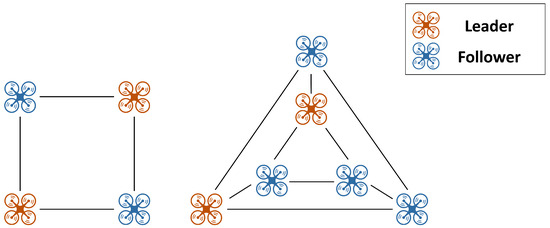
Figure 1.
Examples of bearing-localizable formations without IBR.
In a leader–follower formation system, two leaders must be precisely positioned at designated locations to realize the target formation. If the relative position between the two leaders deviates from that of the desired target formation, as illustrated in Figure 2, the followers adapt to this change and converge to an unintended configuration. Since the overall formation is determined by the relative positions of the leaders, precise control of the leaders is essential to maintain the desired shape. However, in MUM-T systems with two manned leaders, the independent decisions and maneuvers of each leader can inherently destabilize their relative positioning. Consequently, this imposes a significant burden on formation maintenance.
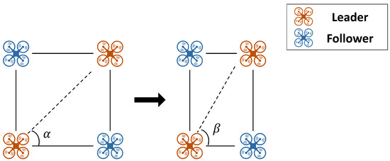
Figure 2.
Example of the effect of leaders’ relative positions on formation.
3. Bearing-Based Target Formation Configuration
To overcome the limitations of conventional bearing-based formation systems, this study introduces a novel framework that employs virtual leaders, as illustrated in Figure 3. First, two virtual leaders are introduced: one located at a distance along the longitudinal axis (aligned with the leader’s heading angle) and the other at a distance along the lateral axis (perpendicular to the heading angle). The position of each follower is then defined to satisfy the bearing constraints with respect to these virtual leaders, with target bearings and . In this formulation, the longitudinal virtual leader determines the forward position of the followers, while the lateral virtual leader governs their lateral position.
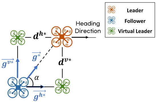
Figure 3.
A novel formation system utilizing virtual leaders.
In conventional bearing-based formation control, the inter-agent bearings are predefined and fixed, thereby limiting flexibility in adjusting the formation. In contrast, in the proposed method, followers are not required to directly satisfy the bearing constraint with respect to the actual leader. Instead, they are guided to satisfy according to the ratio of to . As a result, even if and are predefined bearing constraints, the bearing condition relative to the actual leader can be flexibly adjusted during flight by regulating this ratio. Since and are orthogonal unit vectors aligned with the longitudinal and lateral axes, respectively, modifying the position of one virtual leader does not affect the bearing constraints associated with the other. For instance, even if the longitudinal virtual leader shifts—changing the forward displacement of the follower—the lateral virtual leader still preserves its bearing relationship with the follower. This property allows the formation to be flexibly adjusted while maintaining its structural integrity.
When the leader has a heading angle , the follower’s position can be computed relative to the rotated virtual leaders, as illustrated in Figure 4. The follower satisfies the bearing constraints with respect to the virtual leaders, and . However, it is not aligned with the actual leader’s heading direction and therefore does not conform to the relative bearing constraint between the follower and the leader. This discrepancy arises because the follower does not directly account for the leader’s attitude.
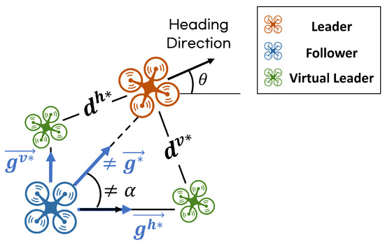
Figure 4.
Formation system without considering the leader’s heading angle.
To address this issue, a rotation matrix incorporating the leader’s heading angle is applied to Equation (8), yielding Equation (10). Through this process, the follower becomes aligned with the leader’s direction while simultaneously satisfying the desired bearing constraints, as illustrated in Figure 5.
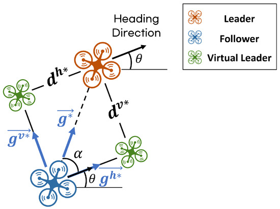
Figure 5.
Formation system considering the leader’s heading angle.
The proposed virtual-leader-based formation system serves as a fundamental module for constructing larger formations. By hierarchically combining these modules, a wide range of formation patterns can be generated. Each module adopts a leader–follower structure, in which lower-layer followers track upper-layer followers in a hierarchical manner. This architecture not only enhances the scalability of the multi-agent system but also allows the entire formation to be controlled by a single leader. In this study, the proposed framework is applied to realize V-shaped and hexagonal formations.
To configure the V-shaped formation, all UAVs—including the virtual leaders—are indexed, and the longitudinal and lateral reference distances assigned to each follower are summarized in Table 1. Here, and denote the longitudinal and lateral reference distances, respectively, with subscripts indicating the leader index and the corresponding virtual leader index. For example, represents the lateral reference distance between UAV 1 (leader) and UAV 1.2 (virtual leader), while represents the longitudinal reference distance between UAV 1 (leader) and UAV 1.3 (virtual leader). Figure 6 illustrates a formation in which the leader is positioned at the front, while the followers form a V-shaped structure to track it. The formation is organized into two layers: in the first layer, UAVs 2 and 3 follow UAV 1 (the leader), and in the second layer, UAVs 2 and 3 act as leaders, with UAVs 4 and 5 assigned to follow them.

Table 1.
Parameters of V-shaped formation.
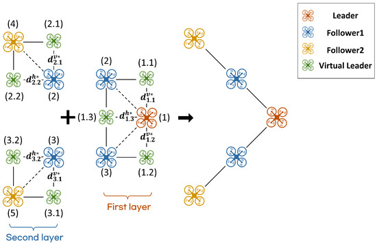
Figure 6.
V-shaped formation system configuration.
Figure 7 illustrates a hexagonal formation in which the followers are arranged around the leader in two layers, with the corresponding formation parameters summarized in Table 2. In the first layer, four follower UAVs 2–5 track UAV 1 (the leader). In the second layer, follower UAVs 6 and 7 are assigned to follow UAVs 2 and 3, and UAVs 4 and 5, respectively, with the first-layer followers serving as leaders.
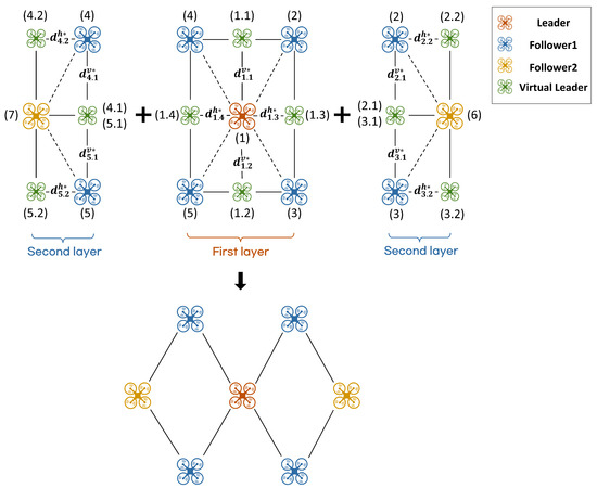
Figure 7.
Hexagonal formation system configuration.
Table 2.
Parameters of hexagonal formation.
When a single follower is required to track two leaders, its position is determined using the method shown in Figure 8a. The positions of leader UAVs 4 and 5 are denoted as points A and C, respectively. UAV 4.1 (a virtual leader), which defines the follower’s lateral position, is determined by the relative location of follower UAV 7 between the two leaders in the target formation. Since follower UAV 7 is positioned at the midpoint of UAVs 4 and 5 in Figure 7, UAV 4.1 is placed at point B, the midpoint of . The heading angle referenced by follower UAV 7 is also defined with respect to this virtual leader and is set to the average of the two leaders’ headings, consistent with the position definition. The longitudinal position of follower UAV 7 is determined using UAVs 4.2 and 5.2, which are aligned with the heading directions of leader UAVs 4 and 5. From the positions of UAVs 4.2 and 5.2, lines perpendicular to their respective heading directions ( and ) are drawn. Let H and E denote the intersections of these lines with , which represents the heading direction of UAV 4.1. The midpoint of is then taken as the longitudinal position of follower UAV 7. If leader UAVs 4 and 5 converge exactly to the target formation defined in the previous layer—thus sharing the same heading angle—points E and H coincide, and follower UAV 7 completes the hexagonal structure shown in Figure 8b.
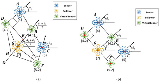
Figure 8.
Positioning a follower with respect to two leaders: (a) different leader heading angles; (b) identical leader heading angles.
By utilizing a formation system based on one or two leaders, the proposed approach can be extended to various formation shapes beyond the previously presented V-shaped and hexagonal configurations. Furthermore, if the longitudinal and lateral positions of followers can be geometrically defined with respect to multiple leaders, formations involving a larger number of leaders can also be constructed. This formation approach provides scalability and flexibility, enabling the construction of more complex and diverse swarm structures.
4. Mode-Based Control Strategy
The formation motion is governed by the leader’s position , which serves as the reference, together with the bearing constraints that define the target formation . Bearing-based formation control regulates the follower positions such that they converge to the desired positions using relative bearing measurements with respect to neighboring nodes. In this study, each UAV is assumed to follow the holonomic dynamic model given in Equation (11), which serves as the basis for tracking and maintaining the target formation:
where , and denote the longitudinal and lateral velocities in the body-fixed frame, is the UAV’s heading angle, and is the angular velocity.
For practical deployment of a formation system, it is essential for followers to not only maintain formation but also actively avoid obstacles in environments. To achieve this, a control architecture was developed that enables each follower to switch between three modes of operation based on its conditions. In the first mode, Formation Tracking Mode, followers initially at arbitrary positions apply formation control to achieve the desired formation by tracking the leader. In the second mode, Collision Avoidance Mode, is activated when an obstacle is detected, temporarily modifying the formation to prevent potential collisions. Finally, the Formation Maintenance Mode maintains the stability of the formation by minimizing unnecessary movements of the followers, which may distort the overall structure.
Each controller is designed independently, with the Formation Tracking Mode described in Section 4.1, the Collision Avoidance Mode presented in Section 4.2, and the Formation Maintenance Mode detailed in Section 4.3. The criteria and procedures for mode switching are also detailed in Section 4.2 and Section 4.3.
4.1. Formation Tracking Mode
Within the hierarchical leader–follower structure, the position, velocity, and heading of each leader vary over time, and it is assumed that each UAV has access to the state information (position and heading) of its designated leader. Before designing the controller that governs the longitudinal and lateral velocities of the follower, the input saturation is taken into account. These constraints are formulated in Equation (12):
where and , , .
Considering the saturation of the control inputs, the controller is designed following the method proposed by Li [35] and is formulated in Equation (13):
where and denote the unit vectors aligned with and orthogonal to the heading direction of agent i, respectively. and represent the rotation matrices corresponding to the heading angles of the leader and each follower, respectively. Indices j and k indicate the virtual leaders that specify the follower’s longitudinal and lateral positions. The parameters and represent the proportional and integral gains for position control, while denotes the proportional gain for heading control. All gains are positive, satisfying .
The position of the follower in the local frame, taking into account the saturation of velocities, is expressed in Equation (14).
To verify that the proposed controller guarantees convergence to the desired target position, the Lyapunov function defined in Equation (15) is considered:
By defining and , the time derivative of the Lyapunov function can be expressed as in Equation (16):
where , and therefore is always positive definite.
The Lyapunov function V is nonnegative, and since its time derivative satisfies , the system is stable. According to LaSalle’s invariance principle [36], the system trajectories converge to the largest invariant set satisfying , which is characterized by
and are independent of each other; therefore, they satisfy and . Under Lemma 1 and Assumption 1, this ensures that the followers converge to the desired target positions.
The angular velocity controller for each follower is designed to align its heading angle with that of the leader, as illustrated in Figure 9.
where and represent the positions of the virtual leader, which determines the lateral reference, and the follower, respectively.
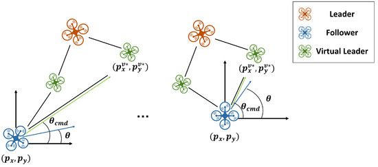
Figure 9.
Concept of the angular velocity controller design for follower.
The follower can reach the target position through forward and lateral movements, and as it converges to the desired position, its heading angle naturally aligns with that of the leader.
4.2. Collision Avoidance Mode
As shown in Section 3, the bearing constraints between a follower and its leader can be regulated by adjusting the relative distances and between the follower and the virtual leaders. In general, leaders generate trajectories to avoid obstacles; however, depending on the formation size and geometry, collisions between followers and obstacles may still occur. To address this issue, followers are designed to switch from the Formation Tracking Mode to the Collision Avoidance Mode when the collision condition specified in Equation (18) is satisfied:
where denotes the position of the nearest obstacle along the y-axis in the body-fixed coordinate frame of the leader being tracked by the follower, and denotes the minimum safety distance required to ensure collision avoidance.
During flight, each follower detects obstacles and computes using the position and heading information received from its leader. If the lateral distance in the target formation exceeds , the follower identifies a potential collision and switches to the Collision Avoidance Mode. In this mode, as illustrated in Figure 10, the lateral distance between the leader and the follower is temporarily adjusted to , enabling the follower to avoid the obstacle.
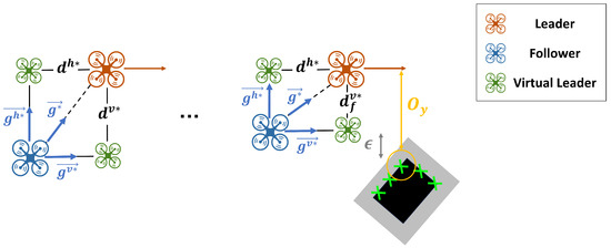
Figure 10.
Example of obstacle-avoidance method.
Equation (19) imposes a constraint preventing the follower from crossing to the opposite side of the leader. In this case, is not instantaneously replaced by ; instead, as illustrated in Figure 11, it is designed to vary continuously over time using a linear transition function.
where and denote the initial and final lateral distances, respectively, represents the initial time when the transition begins, and t is the current time. The parameter denotes the time required for the distance to change from to , and is given by
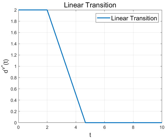
Figure 11.
Example of linear transition function.
When switching from the Formation Tracking Mode to the Collision Avoidance Mode, corresponds to the lateral distance in the original target formation, . is the modified at the moment of mode switching, and denotes the time at which the transition begins. If the adjusted distance changes during obstacle avoidance, the initial value of the transition function is updated to the current lateral distance , and is reset to the corresponding update time. Once obstacle avoidance is completed, the recovery process is performed in the reverse direction, where is set to and is restored to the original .
In the proposed hierarchical leader–follower system, variations in the leader’s heading angle directly affect the target positions of the follower UAVs, often leading to abrupt position changes. Once the formation stabilizes, fluctuations in a follower’s angular velocity can significantly affect the motion of the trailing UAVs. Therefore, in the Collision Avoidance Mode, each follower is designed to use only lateral velocity control to satisfy the bearing constraint with respect to the varying virtual leader, where .
4.3. Formation Maintenance Mode
If the leader enters the Collision Avoidance Mode while the follower remains in the Formation Tracking Mode, the follower unnecessarily changes its position by tracking the leader’s varying lateral displacement, despite the absence of any collision risk. These unnecessary movements propagate to other agents, thereby undermining overall formation consistency and reducing the system’s operational efficiency.
To address this issue, we propose a method in which the follower receives the leader’s lateral displacement and readjusts its virtual leader position in real time, thereby minimizing unnecessary movements. This approach is illustrated using the hexagonal formation structure shown in Figure 12. When the two bottom followers ascend by for obstacle avoidance, the followers in the next layer ascend by . In this process, lower-level followers receive the leader’s lateral displacement from their upper-level leaders in real time and use it to readjust the position of their virtual leader, which determines their own lateral position. This mechanism not only preserves the overall formation by modifying the distance condition in coordination with the upper-level followers performing collision avoidance, but also reduces unnecessary movements among the followers.
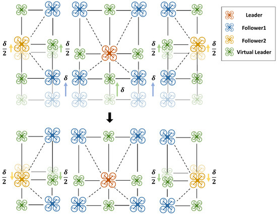
Figure 12.
Formation maintenance via real-time virtual-leader readjustment.
5. Simulation Results
To validate the proposed hierarchical leader–follower bearing-based formation flight system, MATLAB R2024b simulations were conducted for the previously designed V-shaped and hexagonal formations. The simulation scenarios are summarized in Table 3.
Table 3.
Simulation scenarios.
In the first scenario, the leader flies in a straight line at a constant velocity, whereas in the second scenario, the leader follows a circular trajectory. The initial positions and heading angles of both the leader and the followers were randomly assigned, and all followers employed the same controller. The simulation parameters, including the controller gain values, are summarized in Table 4.
Table 4.
Simulation parameters.
The simulation results of the V-shaped formation under straight-line flight are shown in Figure 13. Figure 13a shows the overall simulation results, while Figure 13b–d provide a detailed chronological breakdown. As illustrated in Figure 13b, the followers converge to a V-shaped formation within approximately 2.5 s. Subsequently, in Figure 13d, UAVs 3 and 5 are predicted to collide with an obstacle at 10 s and therefore switch from the Formation Tracking Mode to the Collision Avoidance Mode.
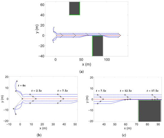
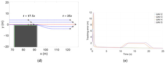
Figure 13.
V-shaped formation control simulation (linear motion): (a) overall simulation result; (b) time interval from 0 s to s; (c) time interval from s to s; (d) time interval from 15 s to 25 s; (e) tracking error of each UAV.
Follower UAV 3 avoids the obstacle nearest to the y-axis relative to its leader (UAV 1) by setting . According to the linear transition function, the virtual leader’s lateral position is adjusted as , enabling the follower to successfully avoid the obstacle. Similarly, UAV 5 switches to the Collision Avoidance Mode with and adjusts its lateral distance accordingly. In such cases, when both the leader UAV and its follower are in the Collision Avoidance Mode, the follower sets to remain aligned with the bearing line of its leader. To avoid the obstacles, UAVs 3 and 5 maintain and for s, after which the formation recovers to its original configuration (see Figure 13d). Figure 13e shows the errors between the desired and actual positions of each follower UAV over time. The results indicate that UAVs 3 and 5 temporarily deviate from the nominal formation during obstacle avoidance, with maximum position errors of and , respectively. Afterward, the UAVs reconverge to the desired formation, confirming the stability and robustness of the proposed method.
The results of the circular flight simulation for the V-shaped formation are shown in Figure 14. The followers converge to the V-shaped formation within approximately s, even under circular motion. Subsequently, in Figure 14c, UAV 4 is predicted to collide with an obstacle at around s and therefore switches to the Collision Avoidance Mode. To ensure a safe distance from the obstacle, the follower adjusts the lateral position of its virtual leader, , and performs the avoidance maneuver. After the first avoidance, the follower returns to the original formation; however, it again detects a potential collision with the corner of the obstacle and repeats the maneuver by readjusting its lateral position. From the error graph in Figure 14e, it can be quantitatively observed that UAV 4 temporarily deviates from the nominal formation during obstacle avoidance, with position errors of approximately and in sequence, before gradually reconverging to the desired formation.
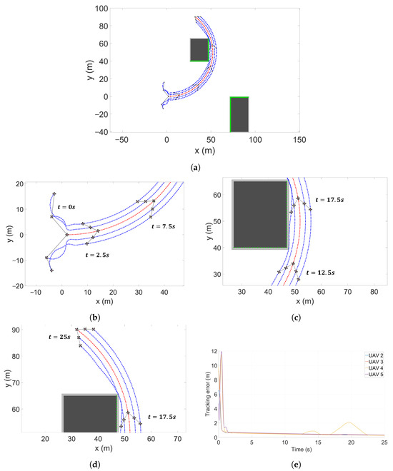
Figure 14.
V-shaped formation control simulation (circular motion): (a) overall simulation result; (b) time interval from 0 s to s; (c) time interval from s to s; (d) time interval from 15 s to 25 s; (e) tracking error of each UAV.
Next, the results of the straight-line flight simulation for the hexagonal formation are illustrated in Figure 15. The followers establish a hexagonal formation within approximately s. At s, UAVs 3 and 5 switch to the Collision Avoidance Mode, adjusting their lateral distance to to modify the formation structure. The lateral positions of UAVs 6 and 7 are determined by the centroid positions of UAVs 2 and 3, and UAVs 4 and 5, respectively. Based on the time-varying , the lateral positions of UAVs 6 and 7 are defined as in Equation (20):
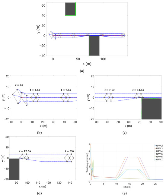
Figure 15.
Hexagonal formation control simulation (linear motion): (a) overall simulation result; (b) time interval from 0 s to s; (c) time interval from s to s; (d) time interval from 15 s to 25 s; (e) tracking error of each UAV.
Although UAVs 6 and 7 do not require obstacle-avoidance maneuvers, their lateral distances are influenced by the avoidance actions of UAVs 3 and 5, as shown in Figure 12 and Equation (20), resulting in unnecessary movements. To mitigate these effects and preserve the desired formation as much as possible, UAVs 6 and 7 transitioned from the Formation Tracking Mode to the Formation Maintenance Mode. UAVs 3 and 5 transmit the changes in their virtual leader’s lateral position, . Using these transmitted values, UAVs 6 and 7 readjust their virtual leader positions as described in Equation (21):
By adjusting their virtual leader positions according to the lateral displacement of their respective leaders, UAVs 6 and 7 are able to maintain the original formation. This is quantitatively verified in the error graph of Figure 15e, where UAVs 3 and 5 exhibit a maximum error of during collision avoidance, while UAVs 6 and 7 show a maximum error of in order to preserve the desired formation.
Figure 16 presents the simulation results for the hexagonal formation under circular motion. From these results, it is observed that the followers rapidly converge to the target formation and maintain a stable configuration even during two consecutive obstacle-avoidance scenarios. Furthermore, the error graph in Figure 16e shows that, while UAVs 2 and 4 perform obstacle avoidance, UAVs 6 and 7 exhibit position errors to preserve the desired formation. This behavior occurs twice, corresponding to the two avoidance maneuvers.
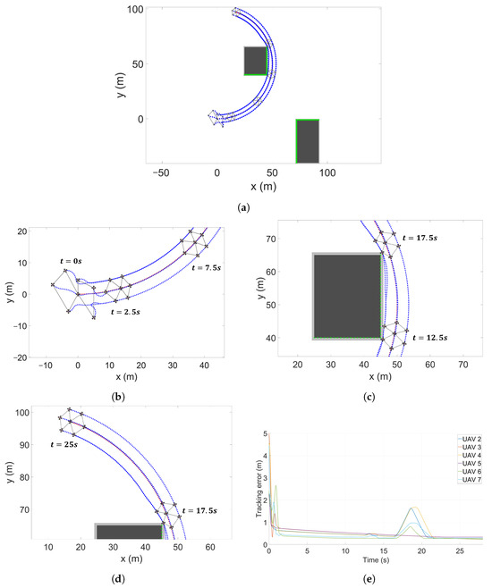
Figure 16.
Hexagonal formation control simulation (circular motion): (a) overall simulation result; (b) time interval from 0 s to s; (c) time interval from s to s; (d) time interval from 15 s to 25 s; (e) tracking error of each UAV.
The formation-flight results (Figure 13, Figure 14, Figure 15 and Figure 16) for two scenarios—straight-line and circular motion—validated the performance of the proposed system. The follower UAVs successfully tracked their designated leaders while forming the specified shapes (V-shaped and hexagonal formation). In addition, each follower assessed potential collisions with obstacles relative to its leader and adjusted the virtual leader’s position to reconfigure the formation, thereby achieving effective obstacle avoidance. Furthermore, based on information received from its leader, each follower reduced unnecessary motions, improving the efficiency of the overall formation system.
6. Conclusions
In this study, we proposed a distributed leader–follower formation flight method for multiple UAV operations. Each UAV maintained the formation using relative bearing and distance information from its designated leader. The limitation of conventional bearing-based methods, which typically require at least two leaders, was addressed by introducing the concept of a virtual leader, enabling the entire formation to be managed efficiently with only a single leader. The proposed method was also shown to be scalable to various formation shapes and sizes through a hierarchical leader–follower structure. In addition, an obstacle-avoidance algorithm tailored to distributed formation operations was presented, addressing challenges such as obstacle avoidance, formation maintenance, and operational efficiency.
Numerical simulations were conducted for representative formation shapes, namely, V-shaped and hexagonal configurations. The results demonstrated that, regardless of initial positions and attitudes, the UAVs rapidly and stably converged to the desired formation while following the moving leader. Moreover, each UAV autonomously adjusted its position to avoid obstacles while minimizing unnecessary maneuvers, thereby enhancing the overall operational efficiency of the formation.
Nevertheless, in practical environments, communication delays between UAVs may arise due to network congestion or distance-related latency, potentially affecting the stability and performance of the proposed system. In addition, owing to the hierarchical leader–follower structure, errors may accumulate as the number of layers increases, causing the overall formation to deviate from the desired configuration. Furthermore, the possibility of collisions between followers or with obstacles during the initial convergence phase was not considered in this study.
Future work will extend the proposed framework to larger UAV formations and address complex issues such as communication delays, error accumulation, and potential collisions. In particular, the current framework does not guarantee collision avoidance among agents during convergence to the target formation. Therefore, future research will focus on developing a distributed collision avoidance strategy to ensure inter-agent safety. In parallel, to enable robust operation in more complex environments involving dynamic or irregular obstacles, a control barrier function (CBF)-based quadratic programming (QP) formulation, similar to that proposed by Huang [37], will be incorporated. The system will be validated in ROS (Robot Operating System) and Gazebo to run simulations that incorporate real-world factors and enable more rigorous performance evaluation, and it will ultimately be validated on real hardware platforms.
Author Contributions
Methodology, J.C.; Supervision, Y.C. All authors have read and agreed to the published version of the manuscript.
Funding
This research was supported by Basic Science Research Program through the National Research Foundation of Korea (NRF) funded by the Ministry of Education (No. RS-2022-NR070875) and Korea Research Institute for defense Technology planning and advancement (KRIT) grant funded by the Korean government (DAPA (Defense Acquisition Program Administration)) (KRIT-CT-22-040, Heterogeneous Satellite constellation based ISR Research Center, 2022).
Data Availability Statement
The data presented in this study are available upon reasonable request from the corresponding author.
Conflicts of Interest
The authors declare no conflicts of interest.
References
- Winnefeld, F.; Kendall, F. Unmanned Sytems Integrated Roadmap; Department of Defense: Washington, DC, USA, 2013.
- Taylor, G.; Turpin, T. Army aviation manned-unmanned teaming (MUM-T): Past, present, and future. In Proceedings of the 18th International Symposium on Aviation Psychology, Dayton, OH, USA, 4–7 May 2015; p. 560. [Google Scholar]
- Kim, B.W.; Choi, G.E. Level and program analytics of MUM-T system. Int. J. Aeronaut. Space Sci. 2024, 25, 593–604. [Google Scholar] [CrossRef]
- Frey, M.A.; Schulte, A. Towards a tactical UAV assessment system to support transport helicopter crews in MUM-T scenarios. In Proceedings of the 2020 IEEE International Conference on Systems, Man, and Cybernetics (SMC), Toronto, ON, Canada, 11–14 October 2020; IEEE: New York, NY, USA, 2020; pp. 3206–3213. [Google Scholar]
- Lindner, S.; Schwerd, S.; Schulte, A. Defining generic tasks to guide UAVs in a MUM-T aerial combat environment. In Intelligent Human Systems Integration 2019: Proceedings of the 2nd International Conference on Intelligent Human Systems Integration (IHSI 2019): Integrating People and Intelligent Systems, San Diego, CA, USA, 7–10 February 2019; Springer: Berlin/Heidelberg, Germany, 2019; pp. 777–782. [Google Scholar]
- Martin, J.; Esteban, S. Relative Estimation and Control for Loyal Wingman MUM-T. Aerospace 2025, 12, 680. [Google Scholar] [CrossRef]
- Penney, H.R. Five Imperatives for Developing Collaborative Combat Aircraft for Teaming Operations; The Mitchell Institute for Aerospace Studies: Arlington, TX, USA, 2022. [Google Scholar]
- Dietterle, R. The future combat systems (FCS) overview. In Proceedings of the MILCOM 2005—2005 IEEE Military Communications Conference, Atlantic City, NJ, USA, 17–20 October 2005; IEEE: New York, NY, USA, 2005; pp. 3269–3273. [Google Scholar]
- Alqudsi, Y.; Makaraci, M. UAV swarms: Research, challenges, and future directions. J. Eng. Appl. Sci. 2025, 72, 12. [Google Scholar] [CrossRef]
- Yan, X.; Jiang, D.; Miao, R.; Li, Y. Formation control and obstacle avoidance algorithm of a multi-USV system based on virtual structure and artificial potential field. J. Mar. Sci. Eng. 2021, 9, 161. [Google Scholar] [CrossRef]
- Pham, T.V.; Nguyen, T.D. path-following formation of fixed-wing UAVs under communication delay: A vector field approach. Drones 2024, 8, 237. [Google Scholar] [CrossRef]
- Desai, J.P.; Ostrowski, J.P.; Kumar, V. Modeling and control of formations of nonholonomic mobile robots. IEEE Trans. Robot. Autom. 2002, 17, 905–908. [Google Scholar] [CrossRef]
- Lewis, M.A.; Tan, K.H. High precision formation control of mobile robots using virtual structures. Auton. Robot. 1997, 4, 387–403. [Google Scholar] [CrossRef]
- Balch, T.; Arkin, R.C. Behavior-based formation control for multirobot teams. IEEE Trans. Robot. Autom. 2002, 14, 926–939. [Google Scholar] [CrossRef]
- Khatib, O. Real-time obstacle avoidance for manipulators and mobile robots. Int. J. Robot. Res. 1986, 5, 90–98. [Google Scholar] [CrossRef]
- Vargas, S.; Becerra, H.M.; Hayet, J.B. MPC-based distributed formation control of multiple quadcopters with obstacle avoidance and connectivity maintenance. Control Eng. Pract. 2022, 121, 105054. [Google Scholar] [CrossRef]
- Huang, S.; Wang, T.; Tang, Y.; Hu, Y.; Xin, G.; Zhou, D. Distributed and scalable cooperative formation of unmanned ground vehicles using deep reinforcement learning. Aerospace 2023, 10, 96. [Google Scholar] [CrossRef]
- Iman, K.F.; Triharjanto, R.H.; Ruyat, Y. Comparative Analysis of a Multi-Layered Weapon System for City Air Defense in the Modern Warfare. Int. J. Humanit. Educ. Soc. Sci. 2023, 3, 1351–1361. [Google Scholar] [CrossRef]
- Yu, A.; Kolotylo, I.; Hashim, H.A.; Eltoukhy, A.E. Electronic Warfare Cyberattacks, Countermeasures and Modern Defensive Strategies of UAV Avionics: A Survey. IEEE Access 2025, 13, 68660–68681. [Google Scholar] [CrossRef]
- Ren, W. Consensus based formation control strategies for multi-vehicle systems. In Proceedings of the 2006 American Control Conference, Minneapolis, MN, USA, 14–16 June 2006; IEEE: New York, NY, USA, 2006; p. 6. [Google Scholar]
- Peng, Z.; Wen, G.; Rahmani, A.; Yu, Y. Distributed consensus-based formation control for multiple nonholonomic mobile robots with a specified reference trajectory. Int. J. Syst. Sci. 2015, 46, 1447–1457. [Google Scholar] [CrossRef]
- Chen, W.; Chen, L.; Mei, J.; Zhang, H. Displacement-based formation control with measurement noises. In Proceedings of the 2023 62nd IEEE Conference on Decision and Control (CDC), Singapore, 13–15 December 2023; IEEE: New York, NY, USA, 2023; pp. 5171–5176. [Google Scholar]
- Mehdifar, F.; Bechlioulis, C.P.; Hashemzadeh, F.; Baradarannia, M. Prescribed performance distance-based formation control of multi-agent systems. Automatica 2020, 119, 109086. [Google Scholar] [CrossRef]
- Zhao, S.; Zelazo, D. Bearing-based formation maneuvering. In Proceedings of the 2015 IEEE International Symposium on Intelligent Control (ISIC), Sydney, Australia, 21–23 September 2015; IEEE: New York, NY, USA, 2015; pp. 658–663. [Google Scholar]
- Van Vu, D.; Trinh, M.H. Decentralized sliding-mode control laws for the bearing-based formation tracking problem. In Proceedings of the 2021 International Conference on Control, Automation and Information Sciences (ICCAIS), Xi’an, China, 14–17 October 2021; IEEE: New York, NY, USA, 2021; pp. 67–72. [Google Scholar]
- Ding, C.; Zhang, J.; Zhang, Z. Nonlinear disturbance observer-based bearing-only unmanned aerial vehicle formation control. Axioms 2023, 12, 768. [Google Scholar] [CrossRef]
- Trinh, M.H.; Zhao, S.; Sun, Z.; Zelazo, D.; Anderson, B.D.; Ahn, H.S. Bearing-based formation control of a group of agents with leader-first follower structure. IEEE Trans. Autom. Control 2018, 64, 598–613. [Google Scholar] [CrossRef]
- Zhao, J.; Yu, X.; Li, X.; Wang, H. Bearing-only formation tracking control of multi-agent systems with local reference frames and constant-velocity leaders. IEEE Control Syst. Lett. 2020, 5, 1–6. [Google Scholar] [CrossRef]
- Zhang, Y.; Xingjian, W.; Shaoping, W.; Xinyu, T. Distributed bearing-based formation control of unmanned aerial vehicle swarm via global orientation estimation. Chin. J. Aeronaut. 2022, 35, 44–58. [Google Scholar] [CrossRef]
- Sial, M.B.; Zhang, Y.; Wang, S.; Ali, S.; Wang, X.; Yang, X.; Liao, Z.; Yang, Z. Bearing-based distributed formation control of unmanned aerial vehicle swarm by quaternion-based attitude synchronization in three-dimensional space. Drones 2022, 6, 227. [Google Scholar] [CrossRef]
- Ramírez-Parada, D.L.; Becerra, H.M.; Toro-Arcila, C.A.; Arechavaleta, G. Vision-Based Formation Control of Quadrotors Using a Bearing-Only Approach. Robotics 2024, 13, 115. [Google Scholar] [CrossRef]
- Zhang, Y.; Wang, S.; Wang, X.; Tian, X. Bearing-based formation control for multiple underactuated autonomous surface vehicles with flexible size scaling. Ocean. Eng. 2023, 267, 113242. [Google Scholar] [CrossRef]
- Ding, C.; Zhang, Z.; Zhang, J. Dynamics event-triggered-based time-varying bearing formation control for UAVs. Drones 2024, 8, 185. [Google Scholar] [CrossRef]
- Zhao, S.; Zelazo, D. Bearing rigidity theory and its applications for control and estimation of network systems: Life beyond distance rigidity. IEEE Control Syst. Mag. 2019, 39, 66–83. [Google Scholar] [CrossRef]
- Li, X.; Er, M.J.; Yang, G.; Wang, N. Bearing-based formation manoeuvre control of nonholonomic multi-agent systems. Int. J. Syst. Sci. 2019, 50, 2993–3002. [Google Scholar] [CrossRef]
- Lin, Z.; Francis, B.; Maggiore, M. Necessary and sufficient graphical conditions for formation control of unicycles. IEEE Trans. Autom. Control 2005, 50, 121–127. [Google Scholar]
- Huang, F.; Duan, M.; Su, H.; Zhu, S. Distributed optimal formation control of second-order multiagent systems with obstacle avoidance. IEEE Control Syst. Lett. 2023, 7, 2647–2652. [Google Scholar] [CrossRef]
Disclaimer/Publisher’s Note: The statements, opinions and data contained in all publications are solely those of the individual author(s) and contributor(s) and not of MDPI and/or the editor(s). MDPI and/or the editor(s) disclaim responsibility for any injury to people or property resulting from any ideas, methods, instructions or products referred to in the content. |
© 2025 by the authors. Licensee MDPI, Basel, Switzerland. This article is an open access article distributed under the terms and conditions of the Creative Commons Attribution (CC BY) license (https://creativecommons.org/licenses/by/4.0/).