Article

GPS-Based Relative Navigation for Laser Crosslink Alignment in the VISION CubeSat Mission

1
Astrodynamics and Control Laboratory, Department of Astronomy, Yonsei University, Seoul 03722, Republic of Korea
2
Department of Satellite Systems, Yonsei University, Seoul 03722, Republic of Korea
*
Author to whom correspondence should be addressed.
Aerospace 2025, 12(10), 928; https://doi.org/10.3390/aerospace12100928 (registering DOI)
Submission received: 2 September 2025 / Revised: 6 October 2025 / Accepted: 8 October 2025 / Published: 15 October 2025
(This article belongs to the Section Astronautics & Space Science)

Abstract

As the demand for high-speed space-borne data transmission grows, CubeSat-based Free-Space Optical Communication (FSOC) offers a viable solution for achieving a Gbps-speed optical intersatellite link on low-cost platforms. The Very-High-Speed Intersatellite Optical Link System Using an Infrared Optical Terminal and Nanosatellite (VISION) mission aims to establish these high-speed laser crosslinks, which require a precise pointing and relative positioning system at relative distances up to 1000 km. A real-time relative navigation system was developed based on dual-frequency GPS pseudorange and carrier-phase measurements, incorporating an adaptive Kalman filter which uses innovation-based covariance matching to dynamically adjust process noise covariance. Hardware-integrated testing with GPS signal generators and onboard receivers validated its performance under realistic conditions, consistently achieving sub-meter positioning accuracy across baselines up to 1000 km. An integrated orbit–attitude simulation further evaluated the feasibility of the Pointing, Acquisition, and Tracking (PAT) system by combining real-time relative navigation outputs with an attitude control system. Simulation results showed that the PAT system maintained a total pointing error of 274.3 μrad, sufficient to sustain stable high-speed optical links. This study demonstrates that the VISION relative navigation and pointing systems, integrated within the PAT framework, enable precise real-time optical intersatellite communication using CubeSats.

1. Introduction

The emergence of non-terrestrial networks (NTNs) has intensified interest in Free-Space Optical Communication (FSOC) as a transformative technology for global connectivity [1]. These technologies are being developed to address the increasing demands for high-capacity and high-speed data transmission. One of the primary NTN platforms utilizes low-Earth-orbit (LEO) satellite constellations, which offer advantages such as reduced communication latency and increased revisit frequency, making them particularly suitable for optical intersatellite links [2]. As data-intensive applications in Earth observation and telecommunications continue to grow, the need for secure and high-speed transmission has positioned FSOC as an effective alternative to traditional radio-frequency (RF) systems [3]. FSOC offers significantly higher bandwidth, smaller terminal sizes, and enhanced link security, with demonstrated potential to achieve data rates exceeding 1 Gbps [4]. Commercial initiatives such as Starlink, OneWeb, Telesat, and Kuiper have further accelerated the integration of optical communication into LEO constellations to address growing demand for high-throughput connectivity and robust space-based services [5].
To enable these laser communication technologies through FSOC satellite systems, the development of formation-flying and swarm satellite technologies has become essential, as these approaches facilitate coordinated operations across distributed spacecraft. Such approaches support a wide range of scientific and commercial objectives, including missions for Earth gravity mapping such as the GRACE mission [6], global elevation modeling, exemplified by the TerraSAR-X/TanDEM-X mission [7], and demonstrations of intersatellite optical crosslinks, such as the CLICK mission [8]. In these missions, precise relative navigation is the key to maintaining spacecraft formation and achieving mission objectives. Moreover, the application of these technologies to smaller platforms has attracted growing attention, with missions such as CanX-4/5 [9] and CANYVAL-C [10], which require real-time baseline estimation capabilities to maintain accurate satellite formations.
To capitalize on FSOC capabilities within more accessible and cost-effective platforms, recent research efforts have focused on CubeSats. Their compact Size, Weight, and Power (SWaP) characteristics, rapid development cycles, and reduced launch costs make them ideal for technology demonstrations and scalable system deployment [3,5]. However, CubeSats are inherently constrained by their limited onboard processing capabilities, reduced structural robustness, and shorter mission lifespans [11,12]. These limitations present challenges for data-intensive applications such as satellite laser communications, which demand precise beam pointing, high platform stability, and stringent thermal and structural control to maintain reliable optical links under dynamic orbital conditions [13].
Despite these inherent limitations, the feasibility of implementing FSOC using CubeSats has been rigorously demonstrated. For instance, Kaushal [14] and Carrasco-Casado [15] conducted comprehensive analyses that identified strategies to mitigate challenges such as limited pointing accuracy and onboard power constraints, emphasizing the importance of integrated system design. Furthermore, several CubeSat missions have successfully demonstrated the practical viability of these technologies in space. For instance, the AeroCube-OCSD mission [16], LaserCube [17], and CubeLCT [18] implemented optical downlink systems utilizing compact, low-power laser terminals onboard CubeSats, thereby achieving desired communication performance despite the inherent platform constraints. These demonstrations underscore the potential of CubeSats to serve as agile, cost-effective platforms for advancing FSOC technologies.
The PIXL-1 mission by DLR further validated CubeSat-based FSOC capability, launching in January 2021 with two 3U CubeSats equipped with CubeLCT terminals capable of supporting optical downlink rates up to 100 Mbps over distances of 1500 km [19,20]. Achieving these data rates required beam tracking accuracy of 90 μrad and fine-pointing within ±0.1°, placing stringent demands on the attitude control systems [18]. The mission’s success demonstrated high-speed optical downlink feasibility and provided operational insights for future optical networks.
Similarly, the CLICK mission, developed by MIT and NASA Ames, aims to demonstrate intersatellite FSOC between two 3U CubeSats across distances ranging from 25 km to 580 km [21]. Scheduled for launch in 2026, CLICK-B/C targets a 20 Mbps crosslink while enabling precise time and range transfer, maintaining beam tracking errors below 40 μrad with only 3.95 W payload power draw [8,22,23]. The mission integrates coarse pointing using spacecraft ADCS enabled by real-time relative navigation, directly addressing Pointing, Acquisition, and Tracking (PAT) system implementation challenges within CubeSat platforms. Despite these advances, achieving stable FSOC links remains a challenge due to limited pointing capability, platform jitter, and environmental disturbances.
Building upon these missions, the Very-High-Speed Intersatellite Optical Link System Using an Infrared Optical Terminal and Nanosatellite (VISION) mission aims to establish Gbps-speed intersatellite links across operational baseline distances of 50, 100, 200, 500, and up to 1000 km within a formation-flying FSOC architecture using two 6U CubeSats [24]. Each satellite carries a laser communication terminal (LCT) with deployable front-end optics to enhance optical power transfer and to meet a stringent beam tracking accuracy requirement within 1 μrad [25]. To maintain stable FSOC operations, VISION integrates a PAT system designed to sustain precise beam alignment over long-baseline formation.
Unlike earlier missions operating under shorter distances or with less stringent pointing requirements, VISION demands sub-meter relative positioning accuracy and precise pointing performance across dynamic baselines up to 1000 km. Achieving these demanding requirements necessitates integrating high-precision relative navigation algorithms with each CubeSat’s attitude determination and control system (ADCS) within the PAT architecture [25]. This integration enables robust real-time beam alignment and maintains stable optical link performance, even in the presence of dynamic orbital motion and environmental disturbances.
The primary objective of this study is to develop and validate a real-time relative navigation system for the VISION laser crosslink mission, utilizing dual-frequency GPS measurements to ensure precise positioning and beam pointing performance. Previous work by Kim [26] presented a preliminary design of the VISION relative navigation framework and evaluated its positioning performance using carrier-phase-based GPS measurements, incorporating an innovation-based covariance-matching approach. Building on this foundation, Kim [27] further integrated the relative navigation system within the PAT architecture in real time, enabling evaluation of beam pointing performance by supplying real-time navigation inputs to the attitude control system.
To validate the performance of the developed filter under realistic operational scenarios, hardware-integrated testing was conducted using a GPS signal generator (Spirent GSS6560) in combination with an onboard NovAtel receiver (OEM719A). In addition, an integrated orbit–attitude simulation environment was developed to assess beam alignment within the PAT system by integrating real-time relative navigation solutions with attitude control dynamics. Simulation results demonstrated that the proposed relative navigation and pointing framework enables precise, real-time optical intersatellite communication using CubeSats, supporting high-speed FSOC operations on low-cost platforms. By ensuring precise formation-keeping and robust optical alignment over long-baseline configurations, this research advances the capabilities of CubeSat-based FSOC systems and establishes a technical foundation for future scalable space-borne optical communication networks.
The remainder of this paper is organized as follows: Section 2 introduces the VISION mission and its system requirements. Section 3 details the development of the relative navigation filter. Section 4 describes the hardware-integrated simulation setup and evaluates relative navigation performance. Section 5 validates the pointing system performance within the PAT architecture. Finally, Section 6 concludes with the successful development and hardware validation of the VISION laser communication alignment.

2. The VISION Mission

2.1. Mission Overview

The VISION mission comprises two symmetric 6U CubeSats operating in a Sun-synchronous low Earth orbit at an altitude of 600 km, separated along track by distances of up to 1000 km. Each satellite is equipped with a dual-frequency GPS receiver (OEM719 by NovAtel Inc., Calgary, AB, Canada) and an ADCS (XACT-50 by Blue Canyon Technologies Inc., Boulder, CO, USA) utilizing three-axis reaction wheels and a star tracker. Relative navigation between CubeSats is performed by exchanging raw L1/L2 GPS measurements via an S-band intersatellite link (ISL).
Although global navigation satellite systems (GNSSs) such as Galileo, GLONASS, and BeiDou can provide additional signals that improve navigation accuracy and satellite geometry, the VISION mission uses GPS-only measurements. GPS alone offers sufficient precision under open-sky low-Earth-orbit conditions, while avoiding the added complexity associated with multi-GNSS integration, including increased power demand, antenna design constraints, and licensing requirements, factors that are often impractical for resource-limited CubeSat platforms [28].
The GPS receivers are mounted in the anti-nadir direction, aligning their GNSS antennas along the radial axis of the radial–tangential–normal (RTN) frame, as illustrated in Figure 1. This configuration improves continuous GNSS visibility and maximizes signal availability for accurate relative navigation during PAT operations, following a similar design approach adopted by the CanX-4/5 mission [29].
The VISION mission comprises three main operational phases: the Launch and Early-Orbit Phase (LEOP), the Drift Recovery and Station-Keeping Phase (DRSKP), and the Normal Operation Phase (NOP). Table 1 summarizes these phases along with their respective operational objectives within a mission timeline that spans over one year.
During the LEOP, the CubeSats initiate attitude stabilization, deploy Ultra-High-Frequency (UHF) antennas and solar panels, and establish initial communication with ground stations after separation from the launch vehicle. The DRSKP involves the controlled separation of the two CubeSats, Altair and Vega, which initially drift to a maximum relative distance of 1000 km and then adjust to a 50 km baseline using their onboard propulsion systems. This phase also includes station-keeping operations and validation of the S-band intersatellite link performance. Finally, NOP involves formation flying over varying baseline distances, ranging from 50 km to 1000 km, to test and validate the performance of the laser crosslink system.
In the NOP, the CubeSats establish high-speed laser communication links. Real-time relative navigation, utilizing dual-frequency GPS observations, is crucial for ensuring precise beam pointing accuracy. To facilitate this, GPS data are exchanged between the satellites via an established S-band ISL, enabling onboard computation of mutual relative state estimations. These relative position solutions are then fed into each satellite’s attitude control system, which employs three-axis reaction wheels to align the optical terminal along the line-of-sight (LOS) vector. The PAT system, which integrates relative navigation, attitude control, and optical feedback mechanisms, ensures accurate beam alignment necessary for maintaining stable laser communication links across intersatellite distances up to 1000 km.
The PAT system operates through a structured sequence comprising three main stages: the Bus Initialization Stage (BIS), the Coarse PAT Stage (CPS), and the Fine PAT Stage (FPS) [24]. An overview of this PAT system architecture is presented in Figure 2.
During the BIS, the real-time relative navigation system computes the intersatellite LOS vectors by processing raw L1/L2 GPS measurements exchanged over the S-band ISL, achieving sub-meter-level accuracy. Based on these solutions, each CubeSat’s ADCS uses its three-axis reaction wheels to orient the payload boresight toward the estimated LOS direction.
In the CPS, a wide optical beam is transmitted along the point-ahead axis of the formation-flying CubeSats and captured by a short-wave infrared camera (CAM). The CAM is triggered just before the beam enters its field of view, and its measurements are fused with ADCS telemetry and relative navigation data to correct any residual angle-of-arrival (AOA) bias.
Once coarse alignment is achieved, the system moves into the FPS, which refines pointing accuracy and suppresses residual jitter using a fast steering mirror (FSM). The FPS procedure consists of hands-off, tracking, and communication sub-stages. While the CAM ensures continued acquisition of the optical beam, a quadrant cell (QC) supplies real-time feedback to the FSM, enabling fine-pointing adjustments. This process reduces the pointing bias to below 30 μrad and suppresses jitter to under 1 μrad. Note that this study excludes detailed analysis of the FPS stage, as its pointing assessment lies outside the present scope.

2.2. Mission Requirements

The subsystem requirements for the VISION mission are derived through a hierarchical flow down from the mission-level constraints. The pointing accuracy requirements of the PAT system are determined by the laser crosslink error budget, which in turn determines the precision requirements for the relative navigation system.
The attitude control system relies on relative navigation data to achieve coarse pointing accuracy within 436.3 μrad. This threshold ensures the optical beam enters the field of view of the short-wave CAM, after which deployable optics correct any remaining pointing biases. Final beam stabilization is then performed using FSM for jitter correction.
Table 2 summarizes the pointing error constraints across the PAT stages, where μ denotes the pointing bias and σ the standard deviation. Using three-axis reaction wheels, each CubeSat aligns its payload along the LOS vector of the optical terminal. The total error budget accounts for uncertainties in attitude control, structural alignment, and relative navigation, establishing the constraint thresholds governing each phase of the PAT sequence.
In the BIS, the relative navigation system performs the initial alignment of each CubeSat’s body and payload along the LOS vector. BIS requirements specify that the pointing bias should remain under 400 μrad, with standard deviation under 60 μrad. To meet these pointing constraints, relative positioning uncertainty must remain approximately below 145 μrad at a 1000 km baseline and below 290 μrad at a 50 km baseline [30].
The CPS is further divided into search, acquisition, and detection phases. During the search phase, the CAM seeks to detect the incoming beam within its field of view. Upon detection, the acquisition phase refines pointing accuracy by calibrating AOA errors, and the detection phase mitigates residual LOS jitter using the FSM. Throughout CPS, the pointing error constraints remain consistent with those of BIS, maintaining a mean and standard deviation of beam pointing less than 400 μrad and 60 μrad, respectively, to maintain a stable laser crosslink and support high-speed data transfer.
FPS refines pointing precision further by minimizing residual jitter, leveraging feedback from both the CAM and a QC. FPS is structured into hands-off and tracking and communication (COM) stages. These stages require stringent requirements, demanding pointing bias below 30 μrad and standard deviation under 1 μrad, with the 1 μrad threshold representing the ultimate precision goal for laser crosslink alignment. Once the optical axes are aligned and the residual pointing requirement is satisfied, an intersatellite optical link between the two CubeSats can be established.
As discussed, successful execution of the PAT sequence requires the system to achieve relative positioning accuracy within 145 μrad and 290 μrad at 1000 km and 50 km baselines, respectively, corresponding to position accuracies of approximately 30 m and 3 m [30]. These values define the minimum requirements for establishing initial beam alignment. To provide a performance margin that accounts for operational uncertainties and dynamic orbital conditions, the VISION mission adopts a more stringent target of sub-meter accuracy in each axis [24]. Meeting this target supports reliable laser beam alignment and ensures the stability of high-speed optical communication links throughout the mission.

3. Development of VISION Relative Navigation System

3.1. Filter System

Accurate relative navigation is critical for enabling formation-flying CubeSats to meet the stringent pointing requirements of FSOC. To support this capability, the VISION mission implements a relative navigation technique that estimates the relative position of satellites in real time while effectively compensating for model uncertainties and measurement noise. The relative navigation system is designed to operate within the limited computational resources of CubeSat platforms while delivering the accuracy required to maintain beam alignment along the LOS vector, which is essential for sustaining a stable optical crosslink.
The architecture of the VISION relative navigation system integrates dual-frequency GPS observations transmitted over the S-band ISL, adaptive Kalman filtering techniques, and integer ambiguity resolution (IAR) using the least-squares ambiguity decorrelation adjustment (LAMBDA) [31] method. Navigation updates are processed at 1 Hz, with raw measurements exchanged via the S-band link at a data rate of 100 kbps to enable onboard single-differenced (SD) processing. To deliver precise real-time estimates under dynamic LEO conditions, the filter system employs an adaptive extended Kalman filter algorithm by addressing the challenges of modeling long-baseline uncertainties in the LEO environment.
The onboard real-time relative navigation system is implemented and operated independently on each CubeSat. By utilizing both pseudorange and carrier-phase observations along with resolved integer ambiguities, the implemented filter processes SD measurements in parallel on each CubeSat’s onboard processor. The filter system is expressed in the standard nonlinear state-space form:
x k + 1 = f ( x k ) + w k , w k N ( 0 , Q k ) ,
z k = h ( x k ) + v k , v k N ( 0 , R k ) ,
where x k denotes the system state described by the dynamic model f, z k is the observation vector defined by the measurement model h, and w k and v k are zero-mean Gaussian noise processes with covariances Q k and R k , respectively.
The corresponding system state vector is defined in Equation (3):
x = Δ Y c Δ δ t Δ I Δ A L 1 Δ A L 2 ,
where Δ denotes the symbol of the SD operator (Vega minus Altair), Δ Y = Δ r Δ v represents the relative position ( Δ r ) and velocity ( Δ v ) of Vega with respect to Altair, c Δ δ t denotes the relative clock bias of Vega with clock bias modeled as a linear drift, Δ I is the ionospheric delay, and Δ A L 1 and Δ A L 2 indicate the differences in L 1 and L 2 carrier-phase ambiguities. The state of the Vega is indirectly estimated by combining absolute and relative state solutions with respect to Altair, and vice versa.
The filter operates through sequential “prediction” and “update” steps [32]. During the prediction step, the dynamic model f is propagated to obtain the a priori state x ¯ k + 1 and covariance P ¯ k + 1 , while the measurement model h is subsequently used in the update step. The dynamics in f include Earth’s central gravitational attraction and the J 2 oblateness perturbation, essential for capturing the long-term secular effects characteristic of LEO orbits, and can incorporate commanded thrust accelerations when present. These accelerations are analytically formulated in the propagation function used for state integration. The state is numerically advanced using a fourth-order Runge–Kutta scheme, as defined in Equations (5) and (6):
x ¯ k + 1 = f x ^ k , t k + 1 ,
f = Δ v Δ a = Δ v r ¨ V e g a r ¨ A l t a i r ,
r ¨ = μ r 3 r + a J 2 + a thrust ,
where x ^ k is the updated state vector at the previous time step ( t k ), Δ v and Δ a are the relative velocity and acceleration vectors of the satellites, μ is Earth’s gravitational constant, a J 2 represents the acceleration due to the J 2 perturbation, and a thrust is the thrust acceleration.
The associated covariance ( P ¯ k + 1 ) is defined as Equation (7):
P ¯ k + 1 = Φ k + 1 P ^ k Φ k + 1 T + Q ^ k + 1 ,
where Φ k + 1 = f k + 1 x ^ k indicates the state transition matrix from t k to t k + 1 , incorporating the time-varying process noise covariance ( Q ^ k + 1 ). Equation (8) defines the structured state transition matrix used for propagating the system states:
Φ k + 1 = Φ Δ Y 0 0 0 0 0 1 0 0 0 0 0 I 0 0 0 0 0 I 0 0 0 0 0 I ,
where Φ Δ Y represents the state transition matrix for the dynamic parameters which propagates the relative position and velocity of the satellite; otherwise, relative clock bias remains constant and ionospheric delay and ambiguities are propagated using n × n identity matrices, where n indicates the total number of GPS observations.
For the measurement model h, the filter processes SD pseudorange and carrier-phase measurements to correct ionospheric delays and clock biases [33] as given in Equations (9) and (10), where Δ ρ j is the SD geometric range, c Δ δ t is the SD relative clock error, Δ I j is the SD ionospheric delay, f L 1 and f L 2 denote the carrier frequencies of the GPS L1 and L2 signals, respectively, λ L 1 and λ L 2 represent their corresponding wavelengths, and Δ N j indicates the SD ambiguity. The relative clock errors and ionospheric delays are modeled as Gaussian random variables in the filter [34].
z k + 1 = h x ¯ k + 1 , t k + 1 ,
h = Δ ρ j + c Δ δ t + Δ I j Δ ρ j + c Δ δ t + f L 1 2 f L 2 2 Δ I j Δ ρ j + c Δ δ t Δ I j + λ L 1 Δ N j Δ ρ j + c Δ δ t f L 1 2 f L 2 2 Δ I j + λ L 2 Δ N j .
During the update step, state and covariance updates are calculated using the Kalman gain defined in Equation (13) as follows:
x ^ k + 1 = x ¯ k + 1 + K k + 1 O b s k + 1 z k + 1 ,
P ^ k + 1 = I K k + 1 H k + 1 P ¯ k + 1 I K k + 1 H k + 1 T + K k + 1 R k + 1 K k + 1 T ,
K k + 1 = P ¯ k + 1 H k + 1 T H k + 1 P ¯ k + 1 H k + 1 + R k + 1 1 ,
where Joseph’s stabilized form [35] is applied to ensure numerical stability and computational efficiency, and K k + 1 denotes the Kalman gain, O b s k + 1 is the difference in the SD GPS observations, H k + 1 is the observation matrix, and R k + 1 is the measurement noise covariance.
The SD observation vector for GPS satellite j is defined in Equation (14):
O b s k + 1 , j = Δ P L 1 j Δ P L 2 j Δ Φ L 1 j Δ Φ L 2 j ,
where Δ P L 1 / L 2 j and Δ Φ L 1 / L 2 j indicate the SD pseudorange and SD carrier-phase observations, respectively, obtained by differencing measurements from the Altair and Vega receivers. Instead of using conventional ionospheric-free linear combinations [36], this study directly models ionospheric delay using the raw dual-frequency observations within the Kalman filter framework, thereby enhancing flexibility and consistency in real-time implementations.
Linearization of the differential model yields the observation matrix H k + 1 as expressed in Equation (15):
H k + 1 = E k + 1 0 1 1 0 0 E k + 1 0 1 f L 1 2 f L 2 2 0 0 E k + 1 0 1 1 λ L 1 0 E k + 1 0 1 f L 1 2 f L 2 2 0 λ L 2 ,
where E k + 1 = r Vega r j r Vega r j represents the line-of-sight partial derivatives between a CubeSat and GPS satellite j, and r j is the position vector of GPS satellite j.

3.2. Adaptive Process Noise Covariance

In Kalman filtering, the process and measurement noise covariance matrices, Q and R, are critical determinants of filter performance, as they define the relative confidence in the system model versus observational data. Accurate adaptation of these covariances is essential for achieving optimal state estimation, particularly under nonlinear dynamics or time-varying conditions [37].
The VISION CubeSats operate with large intersatellite separations of up to 1000 km, making it challenging to accurately model satellite dynamics over long baselines. To address uncertainties in process and measurement noise parameters, a wide range of advanced adaptive filtering techniques have been proposed. For example, random weighted filters and moving horizon estimators based on H or maximum-likelihood principles have demonstrated strong robustness against unknown or time-varying noise statistics [38,39]. In addition, limited memory random weighting schemes have been developed to emphasize recent-innovation utilization with improved stability [40], while extensions to cubature frameworks strengthen consistency in multi-sensor systems [41]. Other methods, such as distributed noise statistics estimators for cubature information filters [42] and windowing-based adaptive unscented Kalman filters employing random weighting [43], further improve estimation reliability under highly dynamic or uncertain environments. While these approaches achieve high accuracy and resilience, they typically require iterative optimization or parallel filter architectures, leading to increased computational complexity that may exceed the onboard processing capabilities of CubeSat platforms.
Given these constraints, the VISION mission adopts more computationally efficient adaptation strategies to ensure real-time feasibility. Covariance-matching methods, which tune noise covariances to align innovation statistics with theoretical expectations [44], and maximum-likelihood estimation (MLE) approaches [45] provide lightweight yet effective alternatives. Similarly, the Sage–Husa algorithm [46], derived from a maximum a posteriori (MAP) framework, and Bayesian-based adaptive filters [47] offer additional flexibility for updating Q and R without significant computational overhead. These low-cost techniques achieve a practical balance between estimation accuracy and algorithmic simplicity.
The baseline for VISION relative navigation draws from the CANYVAL-C implementation [48], which adapted innovation-based covariance matching for both the process noise covariance Q and the measurement noise covariance R using empirically tuned forgetting factors, following the methods of Almagbile [49] and Akhlaghi [50]. In the VISION mission, however, emphasis is placed on dynamically adjusting Q based on estimation consistency, while maintaining a nominally constant R. This design is further supported by findings from the original adaptive extended Kalman filter (AEKF) introduced in the CANYVAL-C mission, which reported that the measurement noise covariance converged almost instantly, whereas the process noise covariance required several thousand seconds to stabilize. These results indicate that accurate modeling of Q exerts a more dominant influence on filter consistency and positioning accuracy than frequent retuning of R under nominal operating conditions [48].
When operating under more demanding operational scenarios, measurement noise characteristics can vary significantly, thereby motivating the use of adaptive-R techniques or robust state-of-the-art filtering architectures. Recent advances, including hypothesis test constrained Kalman filters [51], Mahalanobis distance-based abnormal observation rejection [52], error-detection schemes for tightly coupled INS/GNSS integration [53], and double-channel sequential probability ratio tests for failure detection in multi-sensor systems [54], jointly adapt or re-weight R to enhance resilience against outliers, multipath, and abrupt noise fluctuations. These methods represent important progress toward improving estimation reliability in high-dynamics or degraded operational scenarios.
For the VISION mission, designed primarily for stable, short-duration operations in open-sky low Earth orbit, CubeSat hardware and mission architectures typically prioritize compactness, power efficiency, and rapid deployment over redundancy or fault tolerance [55]. Accordingly, the current implementation adopts a fixed R as a practical, flight-proven compromise between model fidelity and onboard feasibility, consistent with the validated operational regime verified through hardware-integrated testing. In this environment, dominant GNSS error sources such as ionospheric and tropospheric delays, multipath, and receiver noise remain bounded and statistically stable [56]. Focusing the adaptation on Q therefore offers two key benefits: it eliminates reliance on empirically tuned parameters and reduces computational overhead, ensuring compatibility with CubeSat processors. This strategy constitutes a simplified yet generalizable form of adaptive estimation for resource-limited platforms, achieving consistent performance with low computational cost. The detailed derivation of the presented Q-adaptation is provided below.
The innovation vector, b k + 1 , representing the residual between the observed and predicted GPS measurements, is defined as follows:
b k + 1 = z k + 1 h x ¯ k + 1 .
From this innovation, the predicted process noise covariance, Q k + 1 , can be calculated using either the MLE method in Equation (17) or by incorporating forgetting factor α , as in Equation (18), which was used in the CANYVAL-C mission.
Q k + 1 = K k + 1 b k + 1 K k + 1 b k + 1 T ,
Q k + 1 = α Q ^ k + ( 1 α ) K k + 1 b k + 1 K k + 1 b k + 1 T ,
where α [ 0 , 1 ] is an empirically determined constant; while the forgetting factor approach improves numerical stability and guarantees positive definiteness, it introduces additional tuning complexity [56]. This study employs the MLE formulation in Equation (17) within the covariance-matching algorithm, which guarantees positive definiteness of the covariance and thereby removes the requirement for the tuning parameter α .
The covariance-matching algorithm operates under the principle that, in an optimally tuned filter, the predicted innovation covariance should equal the empirical covariance calculated directly from the innovation sequence, assuming R is perfectly known and K k + 1 depends on the relative magnitudes of P ¯ k + 1 and R ^ k + 1 . The adaptive process noise covariance update is computed as follows [57]:
Q ^ k + 1 = tr 1 m i = 1 m b k + 1 i b k + 1 i T R ^ k + 1 tr H k + 1 P ¯ k + 1 H k + 1 T Q ^ k = tr H k + 1 ( Φ k P ^ k Φ k T + Q k + 1 ) H k + 1 T tr H k + 1 ( Φ k P ^ k Φ k T + Q ^ k ) H k + 1 T Q ^ k ,
where Q k + 1 is the innovation-based covariance prediction derived using Equation (17).
Based on the adaptation formulation in Equation (19), a simplified tuning formulation can be derived to reduce computational complexity, as shown in Equation (20). This simplification assumes that the state and process noise covariances are diagonal, allowing the derivative of the measurement model ( H k + 1 ) to be omitted from the formulation:
Q ^ k + 1 = Q k , Φ k P k Φ k T Q k ^ , tr Q k + 1 tr Q k ^ Q k ^ , Φ k P k Φ k T Q k ^ , .
Under this assumption, when the propagated state covariance ( Φ k P ^ k Φ k T ) is greater than or equal to the process noise covariance Q ^ k , the adaptation retains the previous Q ^ k unchanged; conversely, when the process noise covariance dominates, then adaptation is driven primarily by the ratio of Q k + 1 and Q ^ k . It is also important to note that in this study, the dominance of the process noise covariance typically occurs after filter convergence, that is, following successful ambiguity resolution [31], when carrier-phase ambiguities have been fixed to integer values within the current filter framework.
By adopting the simplified innovation-based covariance-matching adaptation without empirical tuning, the VISION relative navigation achieves a computationally efficient and robust solution suitable for real-time onboard navigation in resource-constrained CubeSat missions, ensuring consistent filter performance while balancing simplicity with adaptability across varying operational conditions.

3.3. Ambiguity Resolution and Cycle Slip Effect

Resolving carrier-phase integer ambiguities ( Δ N ) is essential for achieving sub-meter-level positioning accuracy. Once ambiguities are resolved and fixed as constant integers, they remain stable unless disrupted by cycle slips or signal loss. The LAMBDA method is widely used for its efficiency and robustness in resolving GPS ambiguities [58,59]. Reliable ambiguity resolution requires unbiased double-differenced (DD) observations derived from GPS measurements exchanged between two CubeSats.
However, computing DD observations increases onboard processing demands. To mitigate this, the filter primarily processes SD pseudorange and carrier-phase measurements while generating DD ambiguities solely for integer fixing [34]. At the initial satellite lock-on, SD ambiguities are initially estimated using the geometric range divided by the signal wavelength, while other ambiguities retain their prior values. DD float ambiguities are formed by differencing SD ambiguities relative to a reference GPS satellite with resolved integers ( Δ N ref ):
N DD = Δ N 1 L 1 Δ N ref L 1 ; ; Δ N n 1 L 1 Δ N ref L 1 ; Δ N 1 L 2 Δ N ref L 2 ; ; Δ N n 1 L 2 Δ N ref L 2 ,
where n is the number of GPS satellites. The double-differenced covariance matrix ( P DD ) and the transformation matrix (T) of the dual-frequency signals are computed as follows:
P DD = T P SD T T ,
T = 1 0 0 1 0 1 0 1 0 0 1 1 0 0 1 0 0 1 0 1 0 1 0 0 1 1 .
The validation of integer ambiguity resolution uses the ratio test, which compares the best candidate solution ( N b ) to the second-best solution ( N s ), as defined in Equation (24):
N DD N s T P DD 1 N DD N s N DD N b T P DD 1 N DD N b > k ,
where k = 3.0 , aligning with established GPS ambiguity validation practices [60,61], balancing the probability of correct fixing with minimization of false fixes.
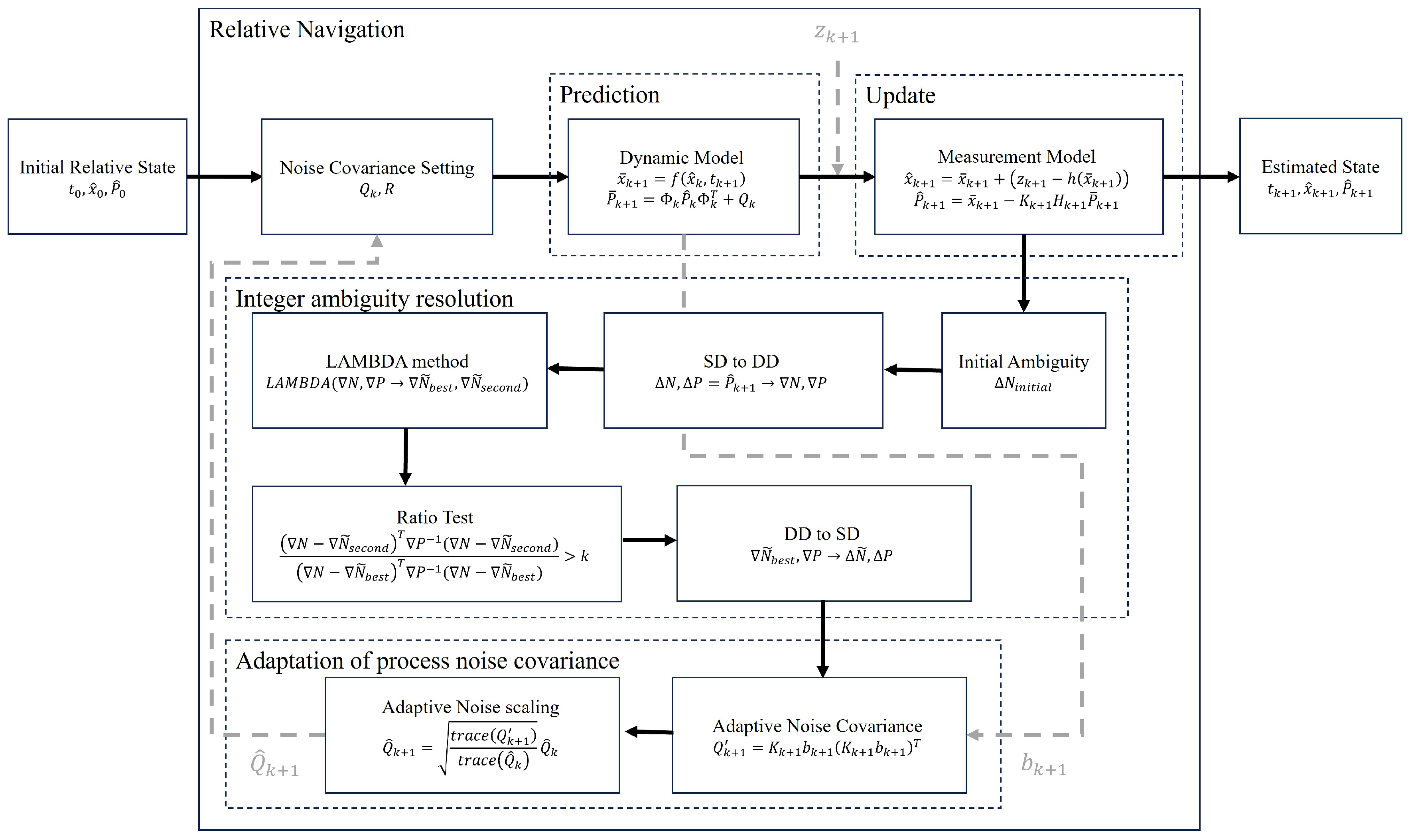
Once DD ambiguities are resolved, they are converted back to SD ambiguities for filter updates. This robust IAR procedure ensures high-accuracy navigation, essential for the mission’s FSOC objectives. Once ambiguities are successfully fixed within the filter system, highly accurate positioning can be achieved, as the filter mainly relies on the fixed-integer values to interpret carrier-phase measurements with confidence. However, the filter remains highly sensitive to signal continuity. Cycle slips, integer jumps caused by the loss of carrier lock, can occur due to power interruptions, low signal-to-noise ratios, oscillator drift, or ionospheric disturbances, leading to degradation in positioning accuracy if left uncorrected [62].
To address this in mission operations and real-world applications, cycle slip detection is implemented within the VISION relative navigation system. This is achieved using the Melbourne–Wübbena (MW) combination, which exploits the geometry-free and ionosphere-free properties of dual-frequency measurements as follows:
L MW = f 1 λ 1 Φ 1 f 2 λ 2 Φ 2 f 1 f 2 f 1 P 1 + f 2 P 2 f 1 + f 2 = λ WL N WL ,
N WL = L MW λ WL = Φ 1 Φ 2 f 1 P 1 + f 2 P 2 λ WL ( f 1 + f 2 ) ,
where λ W L is the wide-lane wavelength and N W L is the wide-lane integer ambiguity. Cycle slips are flagged when the following criteria are met:
N WL ( k + 1 ) N WL ( k ) 1 .
Upon detection, the affected measurement epoch is excluded from processing to prevent corrupted data from destabilizing the filter. Although this removal strategy is conservative, it effectively maintains filter robustness during real-time operations.
Figure 3 presents the complete VISION relative navigation framework, which integrates the simplified AEKF, LAMBDA-based IAR, and real-time Q-adaptation. Cycle slip detection is implemented within the filter loop prior to the measurement update step, ensuring that corrupted data are removed before state estimation. This integrated framework demonstrates the VISION’s capability to maintain high-accuracy performance under dynamic orbital conditions, supporting the feasibility of autonomous FSOC operations on CubeSats.

4. Numerical Assessment with Hardware Integration

4.1. Simulation Setup

To evaluate the feasibility of real-time relative navigation developed for the VISION CubeSat mission, a hardware-integrated simulation testbed was constructed. The system integrates dual-frequency GPS receivers, a pseudo-GPS signal generator, and real-time processing, all configured to operate within the computational and hardware constraints of the VISION architecture. This hardware testbed is developed to evaluate the operational performance and feasibility of CubeSat-based laser communication systems in LEO.
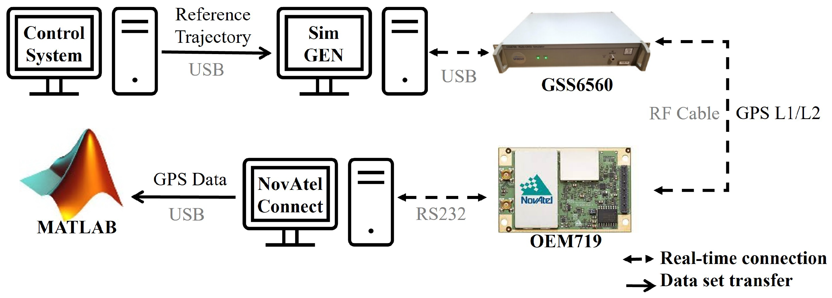
The simulation environment shown in Figure 3 enables validation of relative navigation performance by replicating realistic orbital conditions and GPS signal dynamics. The test setup includes components for system-level evaluation, with particular emphasis on estimation accuracy, hardware compatibility, and real-time operational functionality. Key components include a scenario control system, a Spirent GNSS signal generator, a NovAtel OEM719 dual-frequency GPS receiver, and flight navigation software executing the filter in real time.
Each component is configured according to mission-specific parameters, including orbital geometry, satellite visibility constraints, and actual receiver specifications. The pseudo-GPS signals are transmitted to the NovAtel receiver, which outputs measurements at a frequency of 1 Hz. These measurements are processed in real time by the navigation software to estimate the CubeSats’ relative state vectors. The estimated positions are projected onto the radial–normal (RN) plane, which represents the LOS frame for laser alignment and PAT system feedback.
Figure 4 illustrates the system flow of the hardware-integrated simulation. The control system uses GPS ephemeris data from the latest Yuma almanac provided by CelesTrak to define satellite positions and configure the simulation scenario. These ephemerides are used to model the orbital trajectories of both GPS satellites and the VISION CubeSats in the signal generator, ensuring time-synchronized signal transmission to the receiver. The testbed allows various configurations of orbital elements and baseline separations representative of VISION’s formation-flying geometry.
The VISION mission employs the NovAtel OEM719A dual-frequency GPS receiver, which provides sub-meter RMS positioning accuracy using pseudorange measurements, and sub-centimeter precision with carrier-phase observations. To evaluate this receiver under mission-representative conditions, the hardware simulation employed SimGEN, a GNSS software tool developed by Spirent, which generates customizable mission scenarios simulating the motion of satellites, launch vehicles, or other spacecraft with defined orbital parameters. When paired with an RF signal generator, SimGEN produces real-time pseudo-GNSS signals equivalent to those transmitted by actual GPS satellites.
Using this platform, the VISION relative navigation algorithm was tested in a hardware-integrated simulation with real signal input to the NovAtel receiver. The baseline simulation scenario is summarized in Table 3 and includes orbital configurations, intersatellite baselines, and external force models. The simulation adopted the JGM-3 (70 × 70) gravity model, incorporating complete orbital data for both the GPS satellites and the two VISION CubeSats. The elevation mask angle was set to 5° to reduce the impact of low-elevation signals that are more susceptible to atmospheric disturbances.
Although SimGEN enables high-fidelity L1 signal generation for mission testing, it is limited to single-frequency operation and cannot produce dual-frequency signals. Since VISION relative navigation requires dual-frequency measurements for ionospheric correction, this limitation was addressed through signal modeling. Previous studies [26,27] have investigated this approach in detail, where L2 pseudorange and carrier-phase measurements were analytically generated based on SimGEN’s L1 outputs combined with ionospheric delay models. Kim [26] reported average modeling errors of approximately 8 m for the L2 pseudorange, which confirmed the validity of such pseudo-GPS signals for real-time navigation simulations. These results are consistent with those of [63], which reported modeling errors below 10 m, further confirming the reliability of the modeled L2 data for simulation purposes. With these modeled L2 observations, the VISION relative navigation system was tested using the testbed’s software flight system.
All measurements were generated with synchronized timestamps and antenna delay corrections. Table 4 summarizes the initial filter configuration parameters, which were empirically tuned to reflect the sensor noise and system dynamics observed during real-time integration. A relatively large initial covariance and process noise covariance were intentionally assigned to allow the state estimates to converge gradually over time, reflecting the filter’s adaptation from initial uncertainty toward stable estimation performance. The NovAtel OEM719 receiver was modeled with a worst-case performance profile, consistent with its documented standalone accuracy [64], defining the initial uncertainty for the navigation filter. The simulation began without any prior state history, simulating a cold-start condition where the filter’s initial state estimates relied entirely on raw receiver outputs.

4.2. Simulation Results

The hardware-integrated simulation used baseline separations of 50 km, 100 km, 200 km, 500 km, and 1000 km. Each run incorporated the onboard GPS receiver, modeled L2 signals, and the VISION relative navigation algorithm developed in this study. A 6000 s simulation evaluated relative navigation performance over a full LEO orbital cycle and its influence on PAT system execution.
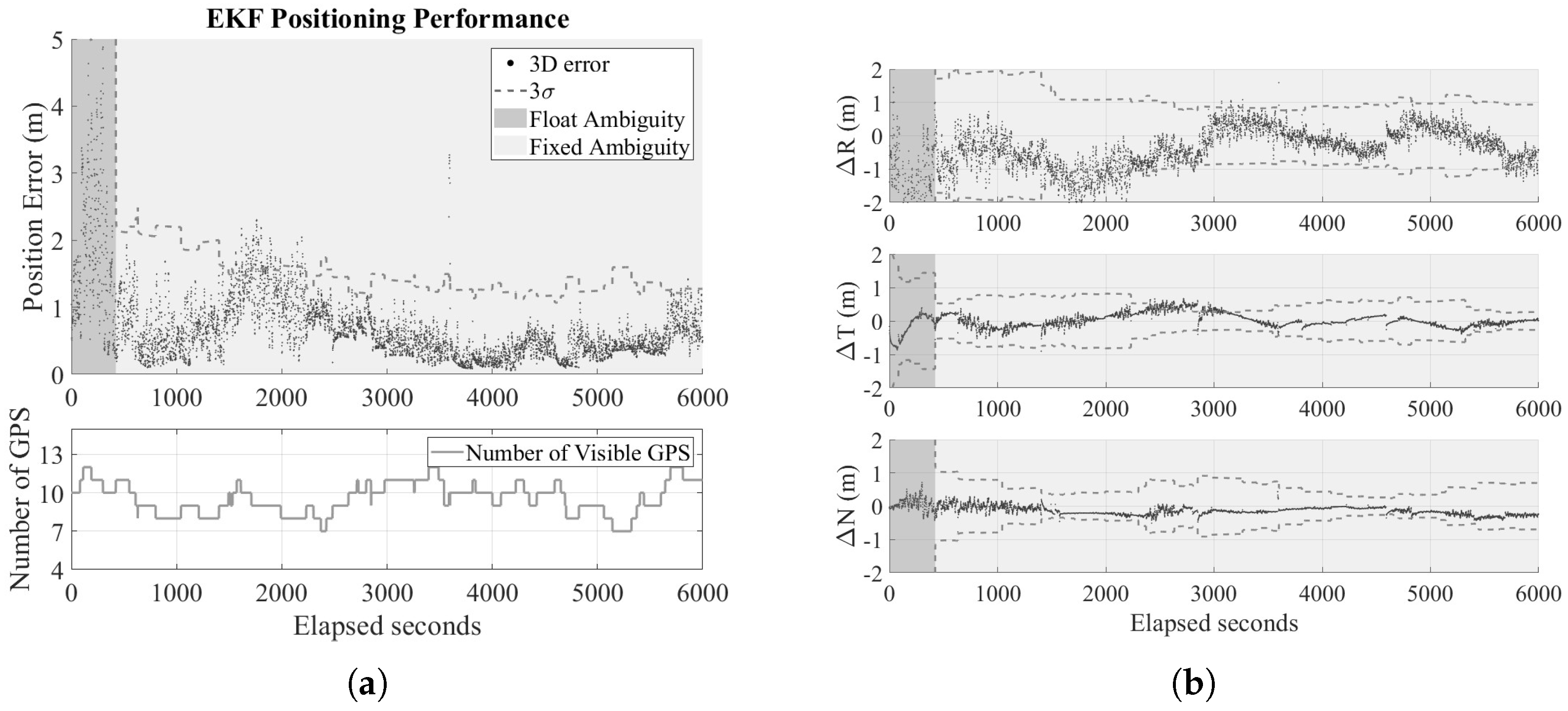
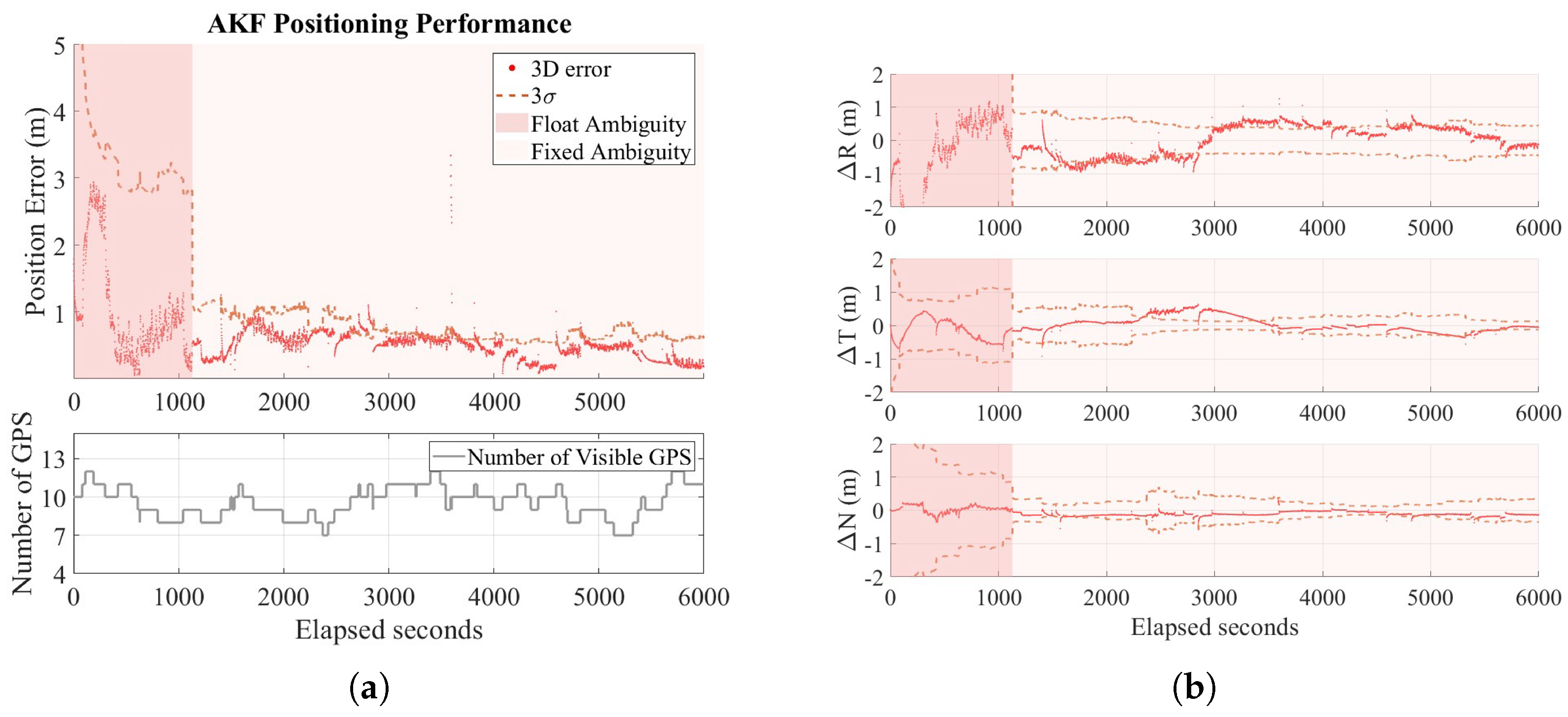
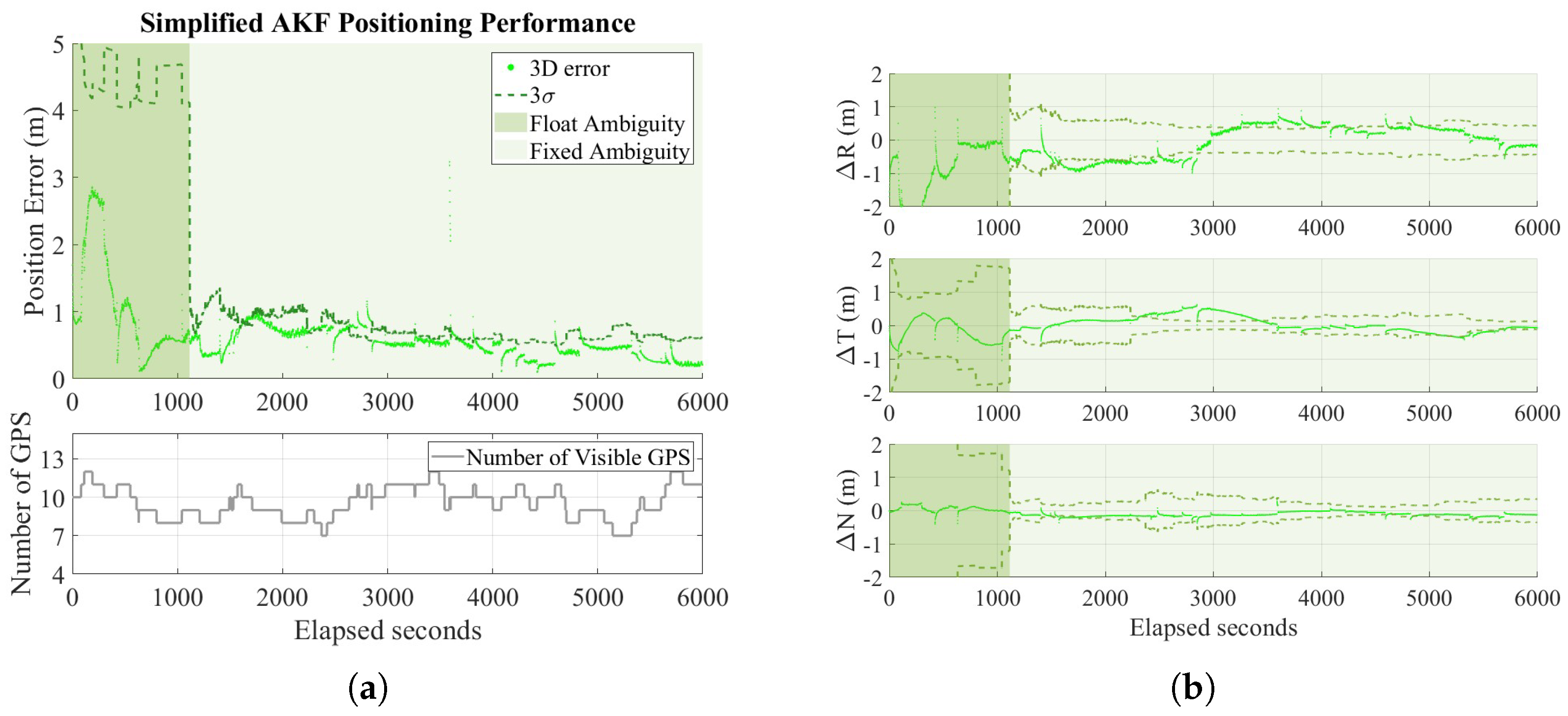
The results show the extended Kalman filter (EKF) as a baseline scenario result where a fixed noise covariance is used, the original AEKF from the CANYVAL-C mission, and the simplified AEKF implemented in the VISION relative navigation system. In this study, the original AEKF applies an empirically selected forgetting factor of α = 0.1 , whereas the VISION relative navigation algorithm adopts a simplified adaptation scheme that eliminates the need for any empirically tuned parameters. Figure 5, Figure 6 and Figure 7 present performance under the worst-case 1000 km baseline scenario.
The hardware simulation results showed that both the original AEKF and the simplified AEKF implemented in the VISION system achieved consistent sub-meter positioning accuracies of 1.12 m and 1.13 m ( 3 σ ) , satisfying the mission’s navigation requirements for intersatellite baselines up to 1000 km. In contrast, the standard EKF, using fixed noise covariances, exhibited degraded performance with positioning errors of 2.47 m ( 3 σ ) . These results confirm that adaptive filtering enhances estimation accuracy under realistic conditions by continuously accounting for time-varying system dynamics, environmental perturbations, and uncertainty growth over extended operations.
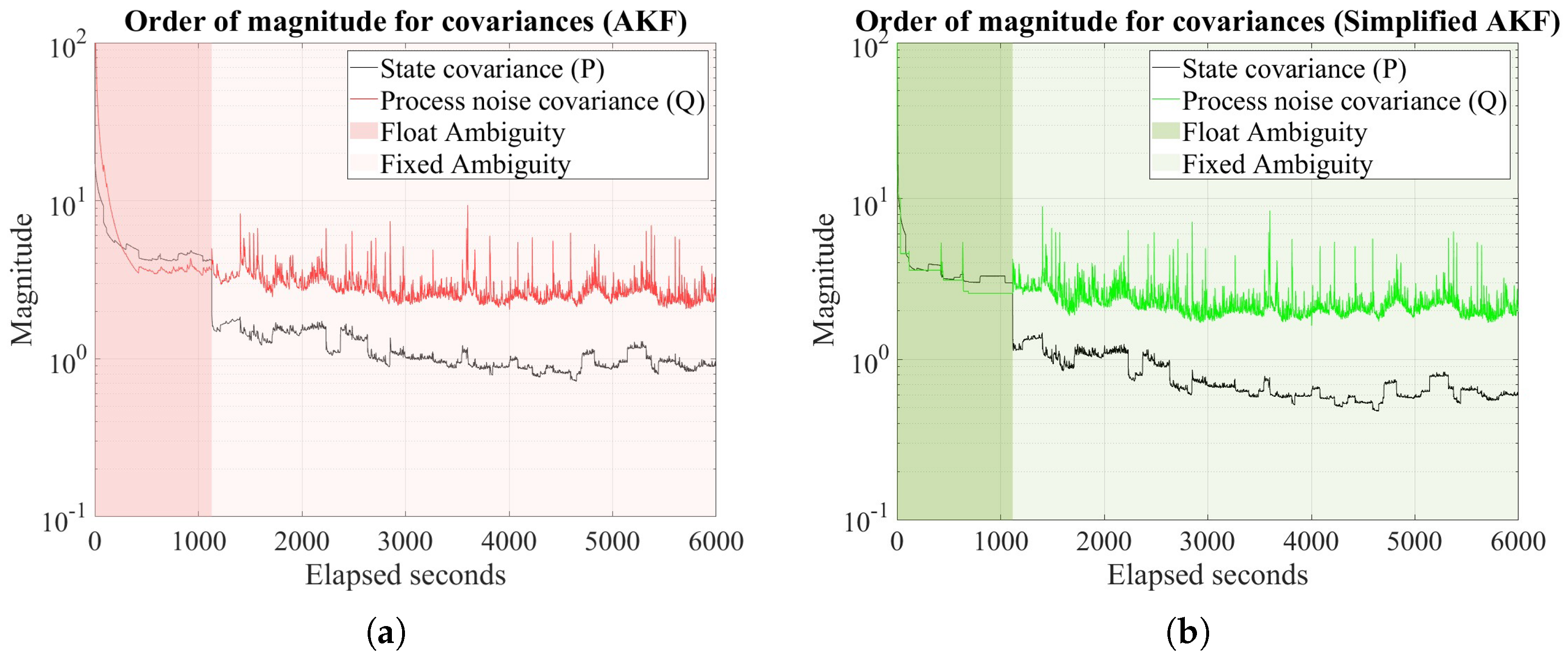
Figure 8 illustrates the evolution of the norm scales for the state covariance ( P ^ k + 1 ) and process noise covariance ( Q ^ k + 1 ) throughout the 6000 s simulation. These results support the underlying assumption of the simplified adaptive Q derivation that the state covariance becomes sufficiently smaller than the process noise covariance once the filter is converged after successful ambiguity resolution.
This validates the use of the simplified Q-adaptation strategy, which leverages the scale difference between state covariance and process noise covariance for computational efficiency. The clear separation in magnitude between the two covariances after convergence supports the validity of the simplified adaptation strategy. In contrast, during the initial convergence phase, when the scale difference is less pronounced, the filter effectively defaults to a standard EKF by holding the process noise covariance fixed in the simplified AEKF approach.
To further validate algorithm performance across different formations, simulations were repeated with baseline separations of 50 km, 100 km, 200 km, and 500 km. Table 5 summarizes these results, with performance evaluated over the final 1000 s of each simulation.
These results demonstrate that VISION relative navigation ensures the sub-meter positioning accuracy achieved by the adaptive filters, satisfying the VISION mission’s requirement of maintaining relative position errors below 1 m per axis, thereby supporting the stringent relative pointing requirements necessary for stable laser crosslink alignment.
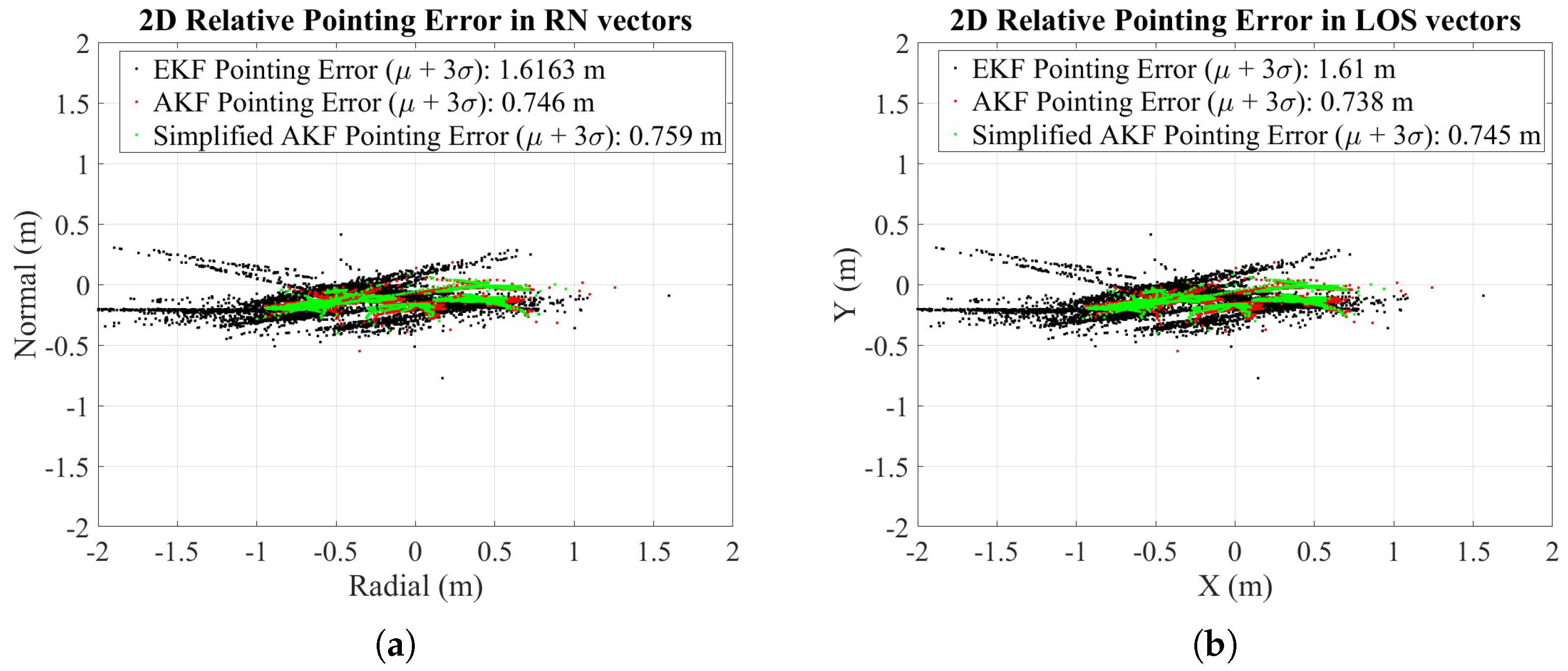
The pointing accuracy of the VISION relative navigation system was rigorously evaluated in Figure 9 to assess compliance with the targeted accuracy requirements of this study. The relatively low errors in the normal ( N ^ ) direction underscore the system’s potential for high pointing stability. The output relative positions projected onto the RN plane provide essential data for simulating attitude control inputs and evaluating pointing stability.
This integration ensures that the testbed verifies the capability of the relative navigation system to support the operation of the optical alignment system. These simulation results show that adaptive filter tuning mitigates the limitations of static covariance settings, thereby enhancing the autonomy and operational flexibility of the relative navigation system.
In addition to navigation accuracy, the relative computational cost of the three filtering schemes was examined by measuring the total simulation time over one LEO orbital period in MATLAB (R2024a). The EKF completed in 14.21 s, the original AEKF in 14.86 s, and the simplified AEKF in 14.60 s. These results indicate that the simplified AEKF successfully reduces the additional overhead introduced by the adaptive mechanism, resulting in a reduced runtime relative to the original AEKF and comparable to that of the EKF, while preserving the accuracy of the original AEKF. It should be noted that these execution times reflect MATLAB’s optimization for matrix operations rather than the performance of an actual onboard processor.
It is important to note that this study employed SD data processing for filter simplicity, rather than the DD format typically used in high-precision ambiguity-fixed solutions. While SD carrier-phase processing with fixed ambiguities can reduce floating ambiguity errors after filter convergence, it retains residual clock errors that would otherwise be eliminated in DD processing. As a result, the pointing improvements achieved through ambiguity fixing were less pronounced in this setup, with ambiguity fixing rates of 53.15% for simplified AEKF, 55.41% for EKF, and 53.80% for AEKF.
These relatively low fixing rates suggest that integrating more robust ambiguity validation strategies or partial-fix acceptance mechanisms could further enhance operational performance in future implementations. These evaluations confirm that the VISION relative navigation achieves a practical balance between accuracy, ambiguity resolution, computational efficiency, and onboard feasibility, demonstrating its effectiveness in constrained CubeSat missions requiring precise optical communication alignment.

5. Performance Evaluation of VISION Laser Crosslink Alignment

5.1. Integrated Orbit–Attitude Framework

Building on the developed relative navigation architecture, an integrated orbit–attitude simulator was developed to test and validate the PAT sequence by incorporating relative navigation outputs as CubeSat control inputs. The simulator, originally developed by Kim [65] and further improved with integrated orbit dynamics in addition to attitude mechanics in Kim [27], combines CubeSat platform characteristics, absolute and relative navigation systems, star tracker models, and control hardware specifications to evaluate pointing errors induced by both internal and external disturbances under VISION mission conditions. Each PAT stage is implemented to operate within its maximum designated duration, as defined in Table 2.
To construct realistic test scenarios, the simulator introduces various biased error sources, including control latency, accumulated attitude errors, orbital actuation uncertainties, optical payload misalignment, and thermal deformation effects. Among these, thermal distortion was identified as a dominant contributor, modeled as a fixed 484.8 μrad bias during beam detection, based on observations by Kim [65] during BIS.
Attitude dynamics were simulated using a fully integrated ADCS module, XACT-50, from Blue Canyon Technologies, with CubeSat pointing control executed via three-axis reaction wheels (RWs). The dynamics model included error sources such as inertial property uncertainty, RW misalignment, onboard timing drift, and external perturbations including gravity-gradient torque, atmospheric drag, solar radiation pressure, magnetic torque, and orbital maneuver thrusts as follows:
r ¨ = μ r 3 r + a J 2 + a air + a mag + a solar + a thrust ,
where r and r ¨ are the satellite position and acceleration vectors, respectively, and the terms a J 2 , a air , a mag , a solar , and a thrust represent accelerations due to the J 2 perturbation, air drag, magnetic dipole torques, solar radiation pressure, and thrust.
While the ADCS incorporates four sensors—a coarse Sun sensor (CSS), magnetometer (MAG), gyroscope (IMU), and star tracker (STT)—it primarily uses the STT due to its precision and low noise. The star tracker has an Earth rejection angle of 27° and a Sun rejection angle of 45°, with an available angular velocity of 5° per second. Its cross-boresight uncertainty is 29.1 μrad, and its about-boresight uncertainty is 193.9 μrad. In addition, the ADCS’s three-axis RWs were modeled based on the performance specifications of the XACT-50 unit, with each wheel capable of reaching up to 6000 RPM, delivering a maximum torque of 7 mNm, and storing up to 50 mNms of angular momentum. Control updates were executed at 1 Hz, alternating 0.5 s between attitude determination and control cycles, with commands generated by the VISION relative navigation algorithm updated in real time using star tracker data.
The complete system architecture integrates relative navigation and attitude control components to support reliable optical alignment. The pointing operations proceed in sequential stages: initial alignment using absolute and relative navigation data, followed by coarse pointing through ADCS control, and final fine adjustments via the FSM. The navigation output is used to center the optical beam within the field of view of a short-wave CAM of each CubeSat, after which deployable front-end optics further reduce residual misalignments.
Throughout the process, pointing disturbances, such as thermal deformation, control delays, and system misalignments, are modeled within the integrated orbit–attitude simulator to assess their impact on pointing performance in realistic mission conditions. Initial conditions, such as the moment of inertia, cross-sectional areas, and attitude quaternions, are summarized in Table 6.
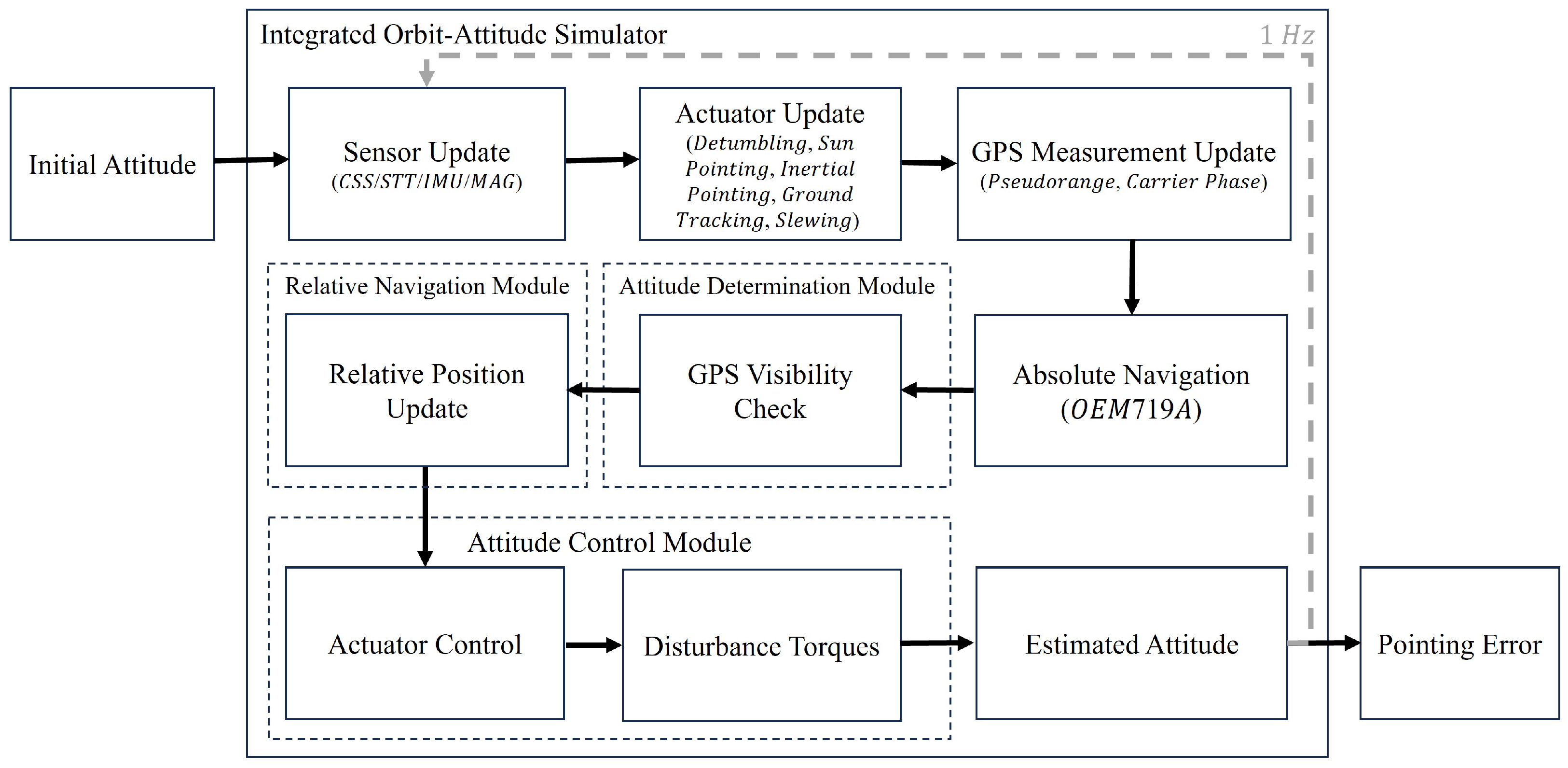
Figure 10 illustrates the integration of orbit dynamics, attitude control, and beam alignment subsystems. The simulator incorporated actuator constraints and control noise consistent with CubeSat ADCS specifications to evaluate PAT performance under realistic mission dynamics.

5.2. Laser Crosslink System Tests

The real-time laser crosslink system and pointing performance were evaluated under a worst-case formation scenario, featuring a 1000 km baseline within the VISION reference orbit. The two CubeSats were separated solely in the along-track direction, while all other orbital elements were held constant to preserve formation geometry.
The complete PAT sequence was executed, incorporating real-time relative navigation and attitude control maneuvers. The evaluation was performed using an 840 s simulation that encompassed the full PAT sequence: BIS (up to 600 s), CPS search (up to 60 s), and CPS acquisition (up to 180 s). The test simultaneously evaluated the accuracy of the VISION relative navigation system integrated with the ADCS. Real-time navigation was critical for generating control commands to align each CubeSat body within the intersatellite LOS-plane. Positioning accuracy was evaluated with respect to each CubeSat’s geometric center, while pointing accuracy was assessed relative to the payload boresight direction.
Figure 11 shows the evolution of relative positioning uncertainties over the simulation. In practice, the relative navigation system is initialized at least 20 min prior to PAT activation, allowing sufficient time for filter convergence. Thus, the results reported here correspond to post-convergence conditions, where carrier-phase ambiguities are assumed to be resolved. The relative navigation filter consistently maintained sub-meter accuracy on each axis, as illustrated in Figure 11. The VISION relative navigation system, employing the simplified AEKF, achieved the required sub-meter accuracy, with 3D positioning errors of 0.929 m ( 3 σ ) and radial, tangential, and normal errors of 0.601 m, 0.906 m, and 0.127 m ( 3 σ ), respectively. These results confirm that the relative navigation system enables reliable PAT execution across the optical alignment phases.
An initial pointing bias of 484.8 μrad from experimental observations in a prior study [65] was introduced to represent initial alignment errors during the BIS stage. A 1 Hz control loop was used to progressively correct this bias. At t = 500 s, the CPS search phase was initiated with the CAM activated for 60 s, marking the start of pointing bias calibration using real-time LOS errors and CAM feedback, as shown in Figure 12. Pointing performance was analyzed using a Rician distribution [23] to characterize residual misalignments.
Following this, the CPS acquisition phase can be executed for up to 180 s as per Table 2. For extended performance evaluation, the simulation continued this phase for a total of 1000 s. During CPS acquisition, the pointing uncertainty was reduced to 274.3 μrad ( 3 σ ) with 99.7% confidence, and the residual pointing bias was corrected to 38.31 μrad, satisfying the mission requirement of 436.3 μrad ( 3 σ ).
These results demonstrate that the proposed 6U CubeSat design, incorporating relative navigation and attitude control system for laser crosslink, achieves total body pointing accuracy within mission constraints during the PAT sequence. The combined performance of the orbit–attitude architecture enables the CubeSats to maintain a 1 Gbps optical crosslink under realistic orbital conditions. Future work will extend this analysis to the FPS stage, incorporating FSM feedback and its closed-loop interaction with the LCT. This will enable system-level evaluation of FSM-based fine-pointing under sub-meter navigation conditions, further guiding optimal design strategies for long-baseline CubeSat-based FSOC missions.

6. Conclusions

This study presented the development and validation of a real-time relative navigation and pointing system for the VISION CubeSat laser crosslink mission. The developed VISION relative navigation algorithm showed consistent sub-meter-level positioning accuracy, with three-dimensional errors remaining below 1 m ( 3 σ ) across intersatellite baselines up to 1000 km, confirming its suitability for precise formation flying. Validation using a hardware-integrated simulation environment with realistic GPS signal modeling demonstrated that the VISION relative navigation system could achieve its performance objectives under mission-representative orbital conditions. In addition, the integrated Pointing, Acquisition, and Tracking (PAT) system met the mission’s pointing requirements, from BIS to CPS acquisition stages, combined with closed-loop camera feedback, maintaining total pointing errors within 274.3 μrad, below the 436.3 μrad threshold required for stable optical links. These results confirm the feasibility of establishing robust Gbps-speed optical crosslinks using low-cost CubeSats and provide a technical foundation for future optical communication missions. Future studies will include implementation of the developed navigation algorithm on a CubeSat onboard system to assess real-time performance in flight-representative conditions, together with the integration of a fast steering mirror (FSM) to enable the fine-pointing accuracy necessary for Gbps-speed optical communication. These efforts will extend the present validation toward full mission operations, ensuring that the VISION system can be robustly deployed in CubeSat optical crosslink demonstrations.

Author Contributions

Conceptualization, P.K., H.-G.R. and Y.E.; methodology, Y.K.; software, Y.K.; validation, Y.K.; formal analysis, Y.K.; investigation, Y.K.; resources, P.K. and Y.K.; data curation, Y.K.; writing—original draft preparation, Y.K.; writing—review and editing, P.K., Y.E. and S.-Y.P.; visualization, Y.K.; supervision, S.-Y.P.; project administration, H.-G.R. and Y.E. All authors have read and agreed to the published version of the manuscript.

Funding

This research was supported by the Challengeable Future Defense Technology Research and Development Program through the Agency For Defense Development (ADD) funded by the Defense Acquisition Program Administration (DAPA) in 2023 (No. 915027201).

Data Availability Statement

The data presented in this study are available on request from author Y.K.

Acknowledgments

This work builds upon the efforts of previous researchers on the VISION mission. The preliminary designs and analyses by Geuk-Nam Kim, Joohee Lee, and Young-Eon Kim formed the basis for this study and provided essential direction for developing the methodologies presented in this study.

Conflicts of Interest

The authors declare no conflicts of interest.

References

  1. NGMN Alliance e.V. Non-Terrestrial Networks Position Paper; Project: Extreme Long-Range Communications for Deep Rural Coverage, Issue 11; NGMN Alliance e.V.: Dusseldorf, Germany, 2019. [Google Scholar]
  2. 3GPP. Study on New Radio (NR) to Support Non-Terrestrial Networks; Technical Report TR 38.811, V15.0.0; 3rd Generation Partnership Project (3GPP): Valbonne, France, 2020. [Google Scholar]
  3. Heidt, H.; Puig-Suari, J.; Moore, A.; Nakasuka, S.; Twiggs, R. CubeSat: A New Generation of Picosatellite for Education and Industry Low-Cost Space Experimentation. In Proceedings of the 14th Annual AIAA/USU Conference on Small Satellites, Logan, UT, USA, 21–24 August 2000. Paper No. SSC00-V-5; Utah State University Digital Commons. [Google Scholar]
  4. Toyoshima, M. Trends in Satellite Communications and the Role of Optical Free-Space Communications. J. Opt. Netw. 2005, 4, 300–311. [Google Scholar] [CrossRef]
  5. Saeed, N.; Elzanaty, A.; Almorad, H.; Dahrouj, H.; Al-Naffouri, T.Y.; Alouini, M.S. CubeSat Communications: Recent Advances and Future Challenges. IEEE Commun. Surv. Tutor. 2020, 22, 1839–1862. [Google Scholar] [CrossRef]
  6. Tapley, B.D.; Bettadpur, S.; Watkins, M.; Reigber, C. The Gravity Recovery and Climate Experiment: Mission Overview and Early Results. Geophys. Res. Lett. 2004, 31, L09607. [Google Scholar] [CrossRef]
  7. Zink, M.; Krieger, G.; Fiedler, H.; Moreira, A. The TanDEM-X Mission: Overview and Status. In Proceedings of the 2007 IEEE International Geoscience and Remote Sensing Symposium (IGARSS), Barcelona, Spain, 23–27 July 2007; pp. 3944–3947. [Google Scholar]
  8. Serra, P.; Cierny, O.; Diez, R.; Grenfell, P.; Gunnison, G.; Kammerer, W.; Kusters, J.; Payne, C.; Murphy, J.; Sevigny, T.; et al. Optical Communications Crosslink Payload Prototype Development for the CubeSat Laser Infrared Crosslink (CLICK) Mission. In Proceedings of the 33rd Annual AIAA/USU Conference on Small Satellites, Logan, UT, USA, 3–8 August 2019. Paper No. SSC19-109; Utah State University Digital Commons. [Google Scholar]
  9. Orr, N.G.; Eyer, J.K.; Larouche, B.P.; Zee, R.E. Precision Formation Flight: The CanX-4 and CanX-5 Dual Nanosatellite Mission. In Proceedings of the 21st Annual AIAA/USU Conference on Small Satellites, Logan, UT, USA, 13–16 August 2007. Paper No. SSC07-VI-2; Utah State University Digital Commons. [Google Scholar]
  10. Kim, G.-N.; Park, S.-Y.; Kang, D.-E.; Son, J.; Lee, T.; Jeon, S.; Kim, N.; Park, Y.-K. Development of CubeSats for CANYVAL-C Mission in Formation Flying. In Proceedings of the Asia Pacific International Symposium on Aerospace Technology (2019: Gold Coast, Qld.), Gold Coast, Australia,, 4–6 December 2019; pp. 813–824, Engineers Australia. [Google Scholar]
  11. Scholz, A.; Giesselmann, J.; Duda, C. CubeSat Technical Aspects. In Proceedings of the 55th International Astronautical Congress of the International Astronautical Federation, the International Academy of Astronautics, and the International Institute of Space Law, Vancouver, BC, Canada, 4–8 October 2004. Paper No. IAC-04-P.5.08. [Google Scholar]
  12. Reddy Tummala, A.; Dutta, A. An Overview of Cube-Satellite Propulsion Technologies and Trends. Aerospace 2017, 4, 58. [Google Scholar] [CrossRef]
  13. Welle, R.P.; Janson, S.; Rowen, D.; Rose, T. CubeSat-Scale Laser Communications. In Proceedings of the 31st Space Symposium, Colorado Springs, CO, USA, 13–16 April 2015. [Google Scholar]
  14. Kaushal, H.; Kaddoum, G. Optical Communication in Space: Challenges and Mitigation Techniques. IEEE Commun. Surv. Tutor. 2016, 19, 57–96. [Google Scholar] [CrossRef]
  15. Carrasco-Casado, A.; Biswas, A.; Fields, R.; Grefenstette, B.; Harrison, F.; Sburlan, S.; Toyoshima, M. Optical Communication on CubeSats-Enabling the Next Era in Space Science. In Proceedings of the 2017 IEEE International Conference on Space Optical Systems and Applications (ICSOS), Tokyo, Japan, 14–16 November 2017; pp. 46–52. [Google Scholar]
  16. Rose, T.S.; Rowen, D.W.; LaLumondiere, S.; Werner, N.I.; Linares, R.; Faler, A.; Wicker, J.; Coffman, C.M.; Maul, G.A.; Chien, D.H.; et al. Optical Communications Downlink from a 1.5 U CubeSat: OCSD Program. In Proceedings of the International Conference on Space Optics-ICSO 2018, Chania, Greece, 9–12 October 2018; Meynart, R., Sodnik, Z., Cugny, B., Eds.; SPIE: Bellingham, WA, USA, 2019; Volume 11180, pp. 201–212. [Google Scholar]
  17. Sansone, F.; Francesconi, A.; Corvaja, R.; Vallone, G.; Antonello, R.; Branz, F.; Villoresi, P. LaserCube Optical Communication Terminal for Nano and Micro Satellites. Acta Astronaut. 2020, 173, 310–319. [Google Scholar] [CrossRef]
  18. Pimentel, P.M.; Rödiger, B.; Schmidt, C.; Fuchs, C.; Rochow, C.; Hiemstra, T.; Zager, A.; Wertz, P.; Knopp, M.; Lehmann, M.; et al. Cube Laser Communication Terminal (CubeLCT) State of the Art. Acta Astronaut. 2023, 211, 326–332. [Google Scholar] [CrossRef]
  19. Rödiger, B.; Menninger, C.; Fuchs, C.; Grillmayer, L.; Arnold, S.; Rochow, C.; Wertz, P.; Schmidt, C. High Data-Rate Optical Communication Payload for CubeSats. In Laser Communication and Propagation Through the Atmosphere and Oceans IX; Hammel, H.T., Shaw, J.A., Eds.; SPIE: Bellingham, WA, USA, 2020; Volume 11506, pp. 12–24. [Google Scholar]
  20. Schmidt, C.; Rödiger, B.; Rosano, J.; Papadopoulos, C.; Hahn, M.T.; Moll, F.; Fuchs, C. DLR’s Optical Communication Terminals for CubeSats. In Proceedings of the 2022 IEEE International Conference on Space Optical Systems and Applications (ICSOS), Cocoa Beach, FL, USA, 28–31 March 2022; pp. 175–180. [Google Scholar]
  21. Kammerer, W.; Grenfell, P.; Hyest, L.; Serra, P.; Tomio, H.; Belsten, N.; Lindsay, C.; Cierny, O.; Cahoy, K.; Clark, M.; et al. CLICK Mission Flight Terminal Optomechanical Integration and Testing. In Proceedings of the International Conference on Space Optics-ICSO 2022, Antibes Juan-les-Pins, France, 3–7 October 2022; Sodnik, Z., Cugny, B., Cornwell, C., Eds.; SPIE: Bellingham, WA, USA, 2023; Volume 12777, pp. 1292–1307. [Google Scholar]
  22. Cahoy, K.; Grenfell, P.; Crews, A.; Long, M.; Serra, P.; Nguyen, A.; Fitzgerald, R.; Haughwout, C.; Diez, R.; Aguilar, A.; et al. The CubeSat Laser Infrared Crosslink Mission (CLICK). In Proceedings of the International Conference on Space Optics-ICSO 2018, Chania, Greece, 9–12 October 2018; Sodnik, Z., Cugny, B., Cornwell, C., Eds.; SPIE: Bellingham, WA, USA, 2019; Volume 11180, pp. 358–369. [Google Scholar]
  23. Grenfell, P.; Aguilar, A.; Cahoy, K.; Long, M. Pointing, Acquisition, and Tracking for Small Satellite Laser Communications. In Proceedings of the 32nd Annual AIAA/USU Conference on Small Satellites, Logan, UT, USA, 4 August 2018. Paper No. SSC18-WKIX-05; Utah State University Digital Commons. [Google Scholar]
  24. Kim, G.-N.; Park, S.-Y.; Seong, S.; Lee, J.; Choi, S.; Kim, Y.-E.; Ryu, H.-G.; Lee, S.; Choi, J.-Y.; Han, S.-K. The VISION–Concept of Laser Crosslink Systems Using Nanosatellites in Formation Flying. Acta Astronaut. 2023, 211, 877–897. [Google Scholar] [CrossRef]
  25. Kim, G.-N.; Park, S.-Y.; Seong, S.; Choi, J.-Y.; Han, S.-K.; Kim, Y.-E.; Choi, S.; Lee, J.; Lee, S.; Ryu, H.-G.; et al. Design of Novel Laser Crosslink Systems Using Nanosatellites in Formation Flying: The VISION. Aerospace 2022, 9, 423. [Google Scholar] [CrossRef]
  26. Kim, Y.; Kim, P.; Ryu, H.-G.; Park, S.-Y. Evaluating the On-Orbit Relative Navigation Performance of Modified Adaptive Kalman Filter with GPS Ambiguity Resolution. In Proceedings of the 2024 International Technical Meeting of The Institute of Navigation, Long Beach, CA, USA, 22–25 January 2024; pp. 658–676. [Google Scholar]
  27. Kim, Y.; Kim, P.; Ryu, H.-G.; Park, S.-Y. Performance Analysis of a Pointing, Acquisition, and Tracking System for the VISION Laser Crosslink Mission. In Proceedings of the 38th Annual AIAA/USU Conference on Small Satellites, Logan, UT, USA, 3 August 2024; pp. 658–676, Paper No.SSC24-S3-08; Utah State University Digital Commons. [Google Scholar]
  28. Minetto, A.; Falco, G.; Dovis, F. On the trade-off between computational complexity and collaborative GNSS hybridization. In Proceedings of the 2019 IEEE 90th Vehicular Technology Conference (VTC2019-Fall), Honolulu, HI, USA, 22–25 September 2019; pp. 1–5. [Google Scholar]
  29. Kahr, E.; Roth, N.; Montenbruck, O.; Risi, B.; Zee, R.E. GPS relative navigation for the CanX-4 and CanX-5 formation-flying nanosatellites. J. Spacecr. Rocket. 2018, 55, 1545–1558. [Google Scholar] [CrossRef]
  30. Lee, J. Development of Relative Navigation Algorithm for Inter-Satellite Free-Space Optical Communication Micro-Satellite Mission in Low Earth Orbit and Long Baseline Environment. Master’s Thesis, Yonsei University, Seoul, Republic of Korea, 2022. [Google Scholar]
  31. Teunissen, P.J.G. The least-squares ambiguity decorrelation adjustment: A method for fast GPS integer ambiguity estimation. J. Geod. 1995, 70, 65–82. [Google Scholar] [CrossRef]
  32. Welch, G.; Bishop, G. An Introduction to the Kalman Filter; University of North Carolina at Chapel Hill, Department of Computer Science: Chapel Hill, NC, USA, 1995. [Google Scholar]
  33. Parkinson, B.W. Global Positioning System: Theory and Applications II. In Progress in Astronautics and Aeronautics; Parkinson, B.W., Spilker, J.J., Eds.; AIAA: Washington, DC, USA, 1996; Volume 164, pp. 3–50. [Google Scholar]
  34. Kroes, R.; Montenbruck, O.; Bertiger, W.; Visser, P. Precise GRACE baseline determination using GPS. GPS Solut. 2005, 9, 21–31. [Google Scholar] [CrossRef]
  35. Bucy, R.S.; Joseph, P.D. Filtering for Stochastic Processes with Applications to Guidance; American Mathematical Society: Providence, RI, USA, 2005; Volume 326. [Google Scholar]
  36. Odijk, D. Ionosphere-Free Phase Combinations for Modernized GPS. J. Surv. Eng. 2003, 129, 165–173. [Google Scholar] [CrossRef]
  37. Simon, D. Optimal State Estimation: Kalman, H Infinity, and Nonlinear Approaches; John Wiley & Sons: Hoboken, NJ, USA, 2006. [Google Scholar]
  38. Gao, Z.; Zhong, Y.; Zong, H.; Gao, G. Adaptive Random Weighted H∞ Estimation for System Noise Statistics. Int. J. Adapt. Control Signal Process. 2025, 39, 214–230. [Google Scholar] [CrossRef]
  39. Gao, B.; Gao, S.; Hu, G.; Zhong, Y.; Gu, C. Maximum likelihood principle and moving horizon estimation based adaptive unscented Kalman filter. Aerosp. Sci. Technol. 2018, 73, 184–196. [Google Scholar] [CrossRef]
  40. Gao, Z.; Zong, H.; Zhong, Y.; Gao, G. Limited memory-based random-weighted Kalman filter. Sensors 2024, 24, 3850. [Google Scholar] [CrossRef]
  41. Zong, H.; Gao, Z.; Wei, W.; Zhong, Y.; Gu, C. Randomly weighted CKF for multisensor integrated systems. J. Sens. 2019, 2019, 1216838. [Google Scholar] [CrossRef]
  42. Zhang, J.; Gao, S.; Zhong, Y.; Qi, X.; Xia, J.; Yang, J. An advanced cubature information filtering for indoor multiple wideband source tracking with a distributed noise statistics estimator. IEEE Access 2019, 7, 151851–151866. [Google Scholar] [CrossRef]
  43. Gao, S.; Hu, G.; Zhong, Y. Windowing and random weighting-based adaptive unscented Kalman filter. Int. J. Adapt. Control Signal Process. 2015, 29, 201–223. [Google Scholar] [CrossRef]
  44. Mehra, R. On the identification of variances and adaptive Kalman filtering. IEEE Trans. Autom. Control 1970, 15, 175–184. [Google Scholar] [CrossRef]
  45. Mohamed, A.H.; Schwarz, K.P. Adaptive Kalman filtering for INS/GPS. J. Geod. 1999, 73, 193–203. [Google Scholar] [CrossRef]
  46. Sage, A.P.; Husa, G.W. Adaptive filtering with unknown prior statistics. In Proceedings of the Joint Automatic Control Conference, Boulder, CO, USA, 5–7 August 1969; pp. 760–769. [Google Scholar]
  47. Särkkä, S.; Nummenmaa, A. Recursive noise adaptive Kalman filtering by variational Bayesian approximations. IEEE Trans. Autom. Control 2009, 54, 596–600. [Google Scholar] [CrossRef]
  48. Lee, E.; Son, J.; Park, S.Y. Relative navigation technique with constrained GNSS data for formation-flying CubeSat mission, CANYVAL-C. NAVIGATION J. Inst. Navig. 2021, 68, 559–575. [Google Scholar] [CrossRef]
  49. Almagbile, A.; Wang, J.; Ding, W. Evaluating the performances of adaptive Kalman filter methods in GPS/INS integration. J. Glob. Position. Syst. 2010, 9, 33–40. [Google Scholar] [CrossRef]
  50. Akhlaghi, S.; Zhou, N.; Huang, Z. Adaptive adjustment of noise covariance in Kalman filter for dynamic state estimation. In Proceedings of the 2017 IEEE Power & Energy Society General Meeting, Chicago, IL, USA, 16–20 July 2017; pp. 1–5. [Google Scholar]
  51. Gao, G.; Gao, B.; Gao, S.; Hu, G.; Zhong, Y. A hypothesis test-constrained robust Kalman filter for INS/GNSS integration with abnormal measurement. IEEE Trans. Veh. Technol. 2022, 72, 1662–1673. [Google Scholar] [CrossRef]
  52. Gao, B.; Hu, G.; Zhu, X.; Zhong, Y. A robust cubature Kalman filter with abnormal observations identification using the Mahalanobis distance criterion for vehicular INS/GNSS integration. Sensors 2019, 19, 5149. [Google Scholar] [CrossRef] [PubMed]
  53. Hu, G.; Gao, B.; Zhong, Y.; Ni, L.; Gu, C. Robust unscented Kalman filtering with measurement error detection for tightly coupled INS/GNSS integration in hypersonic vehicle navigation. IEEE Access 2019, 7, 151409–151421. [Google Scholar] [CrossRef]
  54. Gao, G.; Zhong, Y.; Gao, S.; Gao, B. Double-channel sequential probability ratio test for failure detection in multisensor integrated systems. IEEE Trans. Instrum. Meas. 2021, 70, 1–14. [Google Scholar] [CrossRef]
  55. Langer, M.; Bouwmeester, J. Reliability of CubeSats-Statistical Data, Developers’ Beliefs and the Way Forward. In Proceedings of the 30th Annual AIAA/USU Conference on Small Satellites, Logan, UT, USA, 6–11 August 2016. SSC16-X-2. [Google Scholar]
  56. Zhang, L.; Wang, S.; Selezneva, M.S.; Neusypin, K.A. A new adaptive Kalman filter for navigation systems of carrier-based aircraft. Chin. J. Aeronaut. 2022, 35, 416–425. [Google Scholar] [CrossRef]
  57. Ding, W.; Wang, J.; Rizos, C.; Kinlyside, D. Improving adaptive Kalman estimation in GPS/INS integration. J. Navig. 2007, 60, 517–529. [Google Scholar] [CrossRef]
  58. Teunissen, P.J.; Montenbruck, O. (Eds.) Springer Handbook of Global Navigation Satellite Systems; Springer International Publishing: Cham, Switzerland, 2017; Volume 10. [Google Scholar]
  59. Teunissen, P.J.; Amiri-Simkooei, A.R. Least-squares variance component estimation. J. Geod. 2008, 82, 65–82. [Google Scholar] [CrossRef]
  60. Euler, H.-J.; Schaffrin, B. On a measure for the discernibility between different ambiguity solutions in the static-kinematic GPS-mode. In Kinematic Systems in Geodesy, Surveying, and Remote Sensing: Symposium No. 107, Banff, AB, Canada, 10–13 September 1990; Schwarz, K.-P., Ed.; Springer: New York, NY, USA, 1991; pp. 285–295. [Google Scholar]
  61. Takasu, T.; Yasuda, A. Development of the low-cost RTK-GPS receiver with an open source program package RTKLIB. In Proceedings of the International Symposium on GPS/GNSS, Seogwipo-si, Republic of Korea, 4–6 November 2009; Volume 1, pp. 1–6. [Google Scholar]
  62. Misra, P.; Enge, P. Global positioning system: Signals, measurements, and performance. IEEE Aerosp. Electron. Syst. Mag. 2002, 17, 36–37. [Google Scholar] [CrossRef]
  63. Kuusniemi, H. User-Level Reliability and Quality Monitoring in Satellite-Based Personal Navigation. Ph.D. Thesis, Tampere University of Technology, Tampere, Finland, 2005. [Google Scholar]
  64. Roth, N.H.; Risi, B.; Grant, C.; Zee, R.E. Flight Results from the CanX-4 and CanX-5 Formation Flying Mission. In Proceedings of the Small Satellites, Systems & Services Symposium (4S), Valletta, Malta, 30 May 2016; Volume 30. [Google Scholar]
  65. Kim, Y. Attitude Controller Design and Analysis of Micro-Satellite for Free Space Optical Communication. Master’s Thesis, Yonsei University, Seoul, Republic of Korea, 2022. [Google Scholar]
Figure 1. ( a ) Illustration of the VISION mission (the relative motion of CubeSats is defined in the Earth-centered inertial (ECI) coordinate frame ( X ^ ECI , Y ^ ECI , Z ^ ECI ) ); ( b ) VISION CubeSats (Altair and Vega; each satellite’s body motion and attitude are described in its body-fixed frame ( X ^ Body , Y ^ Body , Z ^ Body ) ).
Aerospace 12 00928 g001
Figure 2. PAT sequence overview for VISION precise pointing task.
Aerospace 12 00928 g002
Figure 3. Flow of the VISION relative navigation system.
Aerospace 12 00928 g003
Figure 4. System interface of the hardware-integrated testbed.
Aerospace 12 00928 g004
Figure 5. ( a ) Three-dimensional relative positioning performance of EKF. ( b ) Relative positioning performance per axis using EKF.
Aerospace 12 00928 g005
Figure 6. ( a ) Three-dimensional relative positioning performance of AEKF. ( b ) Relative positioning performance per axis using AEKF.
Aerospace 12 00928 g006
Figure 7. ( a ) Three-dimensional relative positioning performance of simplified AEKF. ( b ) Relative positioning performance per axis using simplified AEKF.
Aerospace 12 00928 g007
Figure 8. Order of magnitude for state and process covariance in ( a ) an original AEKF and ( b ) a simplified AEKF.
Aerospace 12 00928 g008
Figure 9. Two-dimensional error distributions of ( a ) RN- and ( b ) LOS-plane.
Aerospace 12 00928 g009
Figure 10. Flow of the integrated orbit–attitude simulator.
Aerospace 12 00928 g010
Figure 11. ( a ) Time series of 3D relative positioning error within the PAT system. ( b ) Relative positioning performance per axis.
Aerospace 12 00928 g011
Figure 12. ( a ) Two-dimensional pointing errors in BIS and CPS acquisition phase. ( b ) Time series of pointing errors in each axis.
Aerospace 12 00928 g012
Table 1. Concept of operation with three orbital phases for the VISION mission.
PhaseOperation
LEOPLaunch and separation
Detumbling
Deployment of UHF antenna and solar panel
DRSKPOrbit maneuver and control
Station keeping
Deployment of S-band antenna
NOPRF crosslink
Laser crosslink
Pointing, Acquisition, and Tracking
Table 2. VISION mission requirements for the PAT sequence.
StageOperationDurationSensorError Budget
I. BISBeam detection 600 s Relative Navigation
and Star Tracker
μ < 400 μrad
σ < 60 μrad
II. CPSSearch 60 s CAM Feedback
(Relative Navigation and Star Tracker)
μ < 400 μrad
σ < 60 μrad
Acquisition 180 s CAM Feedback and AOA Calibration
(Relative Navigation and Star Tracker)
Detection 60 s CAM Feedback and FSM
(Relative Navigation and Star Tracker)
III. FPSHand-off 60 s CAM Feedback and FSM and QC
(Relative Navigation and Star Tracker)
μ < 30 μrad
σ < 1 μrad
Tracking and COM> 600 s CAM Feedback and FSM and QC
(Relative Navigation and Star Tracker)
Table 3. Implementation of the simulation scenario.
Orbital ElementValuePropertyValue
Semi-major axis 6978.137 kmMass 9.3 kg
Eccentricity 5.785734 × 10 10 Gravity modelJGM-3 (70 × 70)
Inclination 97.93904 ° Solar radiation pressure1.8
Right ascension of the ascending node 89.83343 ° Drag coefficient2.2
Argument of periapsis 357.4668 ° Solar radiation pressure area0.14 m2
True anomaly (Altair) 2.530662 ° Drag area0.06 m2
True anomaly (Vega) 10.74865 ° Clock modelGauss–Markov 2nd order
Mask angleTEC modelConstant TEC
Table 4. Initial simulation settings of filter parameters.
ParameterValue
Initial covariance of state vector, P Δ Y 1000 m (position), 10 m / s (velocity)
Initial covariance of clock error and ionospheric delay, P c Δ δ t , P Δ I 10 m
Initial process noise of state vector, Q Δ Y 100 m (position), 1 m / s (velocity)
Initial process noise of clock error and ionospheric delay, Q c Δ δ t , Q Δ I 10 m
Fixed process noise of state, clock, and ionospheric delay, Q Δ Y fixed , Q c Δ δ t fixed , Q Δ I fixed 0.1 m
Pseudorange measurement noise, R P , L 1 / L 2 0.8 m
Carrier-phase measurement noise, R C , L 1 / L 2 0.05 m
Table 5. VISION relative positioning performance in all baselines.
Estimated Relative Position Error
Relative Distance50 km100 km200 km500 km1000 km
μ (3D)15.4 cm15.0 cm18.1 cm24.5 cm50.7 cm
3 σ (3D)24.8 cm24.7 cm35.6 cm59.8 cm63.2 cm
R (99.7%)29.3 cm25.0 cm31.0 cm62.8 cm93.9 cm
T (99.7%)27.6 cm27.3 cm35.2 cm37.8 cm58.6 cm
N (99.7%)10.1 cm17.3 cm20.7 cm18.8 cm26.0 cm
Table 6. Initial satellite properties.
PropertyValue
Moment of inertia (MOI) 1.305 × 10 7 5.564 × 10 4 5.841 × 10 4 5.564 × 10 4 9.462 × 10 6 4.244 × 10 5 5.841 × 10 4 4.244 × 10 5 5.749 × 10 6 × 10 8 kg m 2
Cross-section 0.3 × 0.2 m 2 ( + X )
0.3 × 0.2 m 2 ( + Y )
0.3 × 0.2 m 2 ( Z )
Attitude ( q 1 , q 2 , q 3 , q 4 ) = ( 0.1879 , 0.2259 , 0.1417 , 0.4382 )
RWs 200 RPM
Disclaimer/Publisher’s Note: The statements, opinions and data contained in all publications are solely those of the individual author(s) and contributor(s) and not of MDPI and/or the editor(s). MDPI and/or the editor(s) disclaim responsibility for any injury to people or property resulting from any ideas, methods, instructions or products referred to in the content.